EP2113690B1 - Kombinierter Ölring - Google Patents
Kombinierter Ölring Download PDFInfo
- Publication number
- EP2113690B1 EP2113690B1 EP09251112.0A EP09251112A EP2113690B1 EP 2113690 B1 EP2113690 B1 EP 2113690B1 EP 09251112 A EP09251112 A EP 09251112A EP 2113690 B1 EP2113690 B1 EP 2113690B1
- Authority
- EP
- European Patent Office
- Prior art keywords
- oil ring
- side rail
- ring
- oil
- gap
- Prior art date
- Legal status (The legal status is an assumption and is not a legal conclusion. Google has not performed a legal analysis and makes no representation as to the accuracy of the status listed.)
- Not-in-force
Links
- 238000002485 combustion reaction Methods 0.000 description 9
- 230000000052 comparative effect Effects 0.000 description 8
- 238000005516 engineering process Methods 0.000 description 5
- 229910000831 Steel Inorganic materials 0.000 description 4
- 239000010959 steel Substances 0.000 description 4
- 238000007789 sealing Methods 0.000 description 3
- 125000006850 spacer group Chemical group 0.000 description 3
- OKTJSMMVPCPJKN-UHFFFAOYSA-N Carbon Chemical compound [C] OKTJSMMVPCPJKN-UHFFFAOYSA-N 0.000 description 2
- 229910052799 carbon Inorganic materials 0.000 description 2
- 230000000694 effects Effects 0.000 description 2
- 239000010802 sludge Substances 0.000 description 2
- 230000006835 compression Effects 0.000 description 1
- 238000007906 compression Methods 0.000 description 1
- 239000000463 material Substances 0.000 description 1
- 239000003595 mist Substances 0.000 description 1
- 238000005086 pumping Methods 0.000 description 1
- 238000007790 scraping Methods 0.000 description 1
Images


Classifications
-
- F—MECHANICAL ENGINEERING; LIGHTING; HEATING; WEAPONS; BLASTING
- F16—ENGINEERING ELEMENTS AND UNITS; GENERAL MEASURES FOR PRODUCING AND MAINTAINING EFFECTIVE FUNCTIONING OF MACHINES OR INSTALLATIONS; THERMAL INSULATION IN GENERAL
- F16J—PISTONS; CYLINDERS; SEALINGS
- F16J9/00—Piston-rings, e.g. non-metallic piston-rings, seats therefor; Ring sealings of similar construction
- F16J9/06—Piston-rings, e.g. non-metallic piston-rings, seats therefor; Ring sealings of similar construction using separate springs or elastic elements expanding the rings; Springs therefor ; Expansion by wedging
- F16J9/061—Piston-rings, e.g. non-metallic piston-rings, seats therefor; Ring sealings of similar construction using separate springs or elastic elements expanding the rings; Springs therefor ; Expansion by wedging using metallic coiled or blade springs
- F16J9/062—Coiled spring along the entire circumference
-
- F—MECHANICAL ENGINEERING; LIGHTING; HEATING; WEAPONS; BLASTING
- F16—ENGINEERING ELEMENTS AND UNITS; GENERAL MEASURES FOR PRODUCING AND MAINTAINING EFFECTIVE FUNCTIONING OF MACHINES OR INSTALLATIONS; THERMAL INSULATION IN GENERAL
- F16J—PISTONS; CYLINDERS; SEALINGS
- F16J9/00—Piston-rings, e.g. non-metallic piston-rings, seats therefor; Ring sealings of similar construction
- F16J9/06—Piston-rings, e.g. non-metallic piston-rings, seats therefor; Ring sealings of similar construction using separate springs or elastic elements expanding the rings; Springs therefor ; Expansion by wedging
- F16J9/064—Rings with a flat annular side rail
Definitions
- the present invention relates to a combined oil ring utilized in internal combustion engines, and relates in particular to a combined oil ring with low oil consumption.
- a compression ring functioning mainly as a gas seal; and an oil control ring functioning mainly to control the thickness of the oil film on the wall surface of the cylinder bore are mounted on a piston in an internal combustion engine.
- the oil control ring is mainly a steel combined oil ring with a spacer expander and separate upper and lower rails; or a steel combined oil ring with an integrated upper and lower rail structure and having a coil expander. These oil control rings control the thickness of the oil film on the cylinder wall by pressing the rail section against the inner wall surface of the cylinder bore by the expander to scrape off oil on the inner wall surface of the cylinder bore.
- oil loss occurs via the gap because the gap positions on the upper and lower rails are at the same or nearby positions along the periphery.
- the oil mist that passed through the gap of the lower rail and the oil remaining on the cylinder wall due to the gap of the lower rail tend to easily pass through the gap of the upper rail and enter the combustion chamber.
- This oil loss phenomenon is particularly drastic when the gaps of the upper and lower rails are aligned with each other since the combustion chamber reaches a negative pressure during deceleration where there is an engine braking effect.
- the sealing on the upper side of the piston ring groove is weak in the combined oil rings with an integrated upper and lower rail structure so that oil loss occurs in the clearance between the upper surface of the ring groove and the upper surface of the oil ring.
- This oil loss phenomenon becomes especially drastic during deceleration where engine braking occurs, because the combustion chamber reaches a negative pressure.
- Japanese Patent Non-examined Publication No. 50-94311 has the problem that the belleville spring restricts the oil ring and impedes the oil ring movement, which is sometimes a factor causing oil consumption to worsen.
- the technology disclosed in Japanese Patent Non-examined Publication No. 4-88261 and Japanese Patent Non-examined Publication No. 5-231540 contains no oil ring having upper and lower rails formed integrally at the outer circumferential side of the oil ring to slide on the cylinder wall.
- the side rail on the upper side is pressed against the upper surface of the ring groove so that poor conformability of the upper side rail on the inner circumferential surface of the cylinder due to carbon sludge deposits, as well as wear at the contact portion between the side rail pressing section and the side rail sometimes inhibit the oil control function.
- GB-1125031 discloses a device for exerting a radially directed thrust for piston rings comprising an annular thrust strip or band that operatively presses the oil-scraping elements of the piston ring against the cylinder walls.
- US-5603512 discloses an oil control ring assembly comprising a side rail member formed of a U-shaped sealing ring component that substantially circumferentially surrounds and radially overlies the scraper ring.
- the U-shaped component is forced against the upper surface of a groove in a piston.
- An object of the present invention is to reduce oil consumption in a combined oil ring including an oil ring having upper and lower rails formed integrally at an outer circumferential side of the oil ring to slide on a cylinder wall.
- the gaps of the oil ring and the side rail are preferably mutually offset from each other along the circumference.
- At least one of the gaps of the oil ring and the side rail is preferably an oblique gap along the radius.
- the oblique gap along the radius here means a gap with a gap shape formed of the opposite end surfaces of the oil ring that are positioned at an angle relative to the normal line of the circle of the cylinder bore inner circumference that contacts the outer circumference of the oil ring when the oil ring is installed in the cylinder.
- the gaps of the oil ring and the side rail are preferably oblique gaps along the radius and preferably face mutually opposite from each other.
- the radial thickness of the side rail is larger than the radial thickness of the oil ring.
- the side rail preferably possesses a slight radial pressing force against the cylinder wall.
- the present invention uses the side rail capable of closing the gap of the oil ring and therefore can reduce oil leakage from the gap and lower oil consumption.
- the side rail possesses a smaller mass than the oil ring, and compared to the coil expander possesses a smaller outward force on the surface of the cylinder bore. Therefore, when the piston lowers during engine braking where the combustion chamber reaches a negative pressure, the side rail is raised by the negative pressure and inertial force, and is easily pressed against the upper surface of the ring groove.
- the side rail consequently closes the clearance between the surface of the cylinder bore and the outer circumferential surface of the piston so that the quantity of oil pumped up into the combustion chamber can be reduced and oil consumption can therefore be smaller.
- oil ring movement is not obstructed because there is no torsion in the side rail along the axial direction of the oil ring.
- the coil expander does not press the side rail against the upper surface of the ring groove so that there is no interference with oil control functions of the combined oil ring even if deposits such as carbon sludge occur on the upper surface of the ring groove.
- the gap positions are preferably offset from each other by 180 degrees, and a rotation preventing member may be added to the side rail.
- At least one of gaps of the oil ring and the side rail as an oblique gap along the radius will narrow the oil path of the gap and so is effective in reducing oil consumption.
- Setting the gaps of the oil ring and the side rail as oblique gaps along the radius and making them face mutually opposite from each other is particularly effective in lowering oil consumption even further.
- the oil path through the gap is narrowed and is effective in reducing oil consumption even if the oil ring and/or the side rail rotates during operation and the gap positions align with each other.
- the sealing with the outer circumference can be improved if the side rail possesses a slight radial pressing force against the cylinder wall. Moreover, the rotation of the side rail can be prevented and therefore aligning with the gap of the oil ring can be prevented. Setting the gap dimensions to 0 ⁇ L1 - L2 ⁇ 3mm where L1 is the gap dimension while the side rail is in the free state, and L2 is the gap dimension during assembly of the side rail will prove adequate for providing the side rail with a slight expansive force. A slight expansive force of the side rail increases little friction.
- the side rail may also be set so that there is no radial pressing force on the cylinder wall.
- a combined oil ring 1 is made up of an oil ring 2, a coil expander 3, and a side rail 4.
- the combined oil ring 1 is mounted on a ring groove 6 of a piston 5.
- the oil ring 2 is a steel ring having an approximately I-shaped cross section and including an oblique gap 2a along the radius.
- the oblique gap 2a along the radius is a gap with a gap shape formed of the opposite end surfaces of the oil ring 2 that are positioned at an angle relative to the normal line of the circle of a cylinder 10 bore inner circumference that contacts the outer circumference of the oil ring 2 when the oil ring 2 is installed in the cylinder 10.
- the oil ring 2 includes a pair of upper and lower rails 7 and 8 extending along the circumference, and a straight, thin-walled web 9 connecting the pair of upper and lower rails 7 and 8 and extending along the circumference.
- the outer circumferential surfaces of the upper and lower rails 7 and 8 respectively make up sliding surfaces 12 that contact the inner circumferential surface 11 of the cylinder 10.
- the upper and lower rails 7 and 8 and the web 9 form an outer circumferential groove 13. Oil scraped on the inner circumferential surface 11 of the cylinder 10 by the lower rail 8 drops directly into the oil pan. Oil scraped by the upper rail 7 moves from the outer circumferential groove 13 to the inner circumferential side of the oil ring 2 by way of multiple window holes 14 formed at intervals along the circumference on the web 9, and then moves by way of an oil path (not shown in the drawing) formed on the piston 5 and drops into the oil pan.
- An inner circumferential groove 15 is formed from the upper and lower rails 7 and 8 and the web 9.
- the coil expander 3 is mounted in this groove 15.
- the coil expander 3 is made such that a wire material is wound in a coil form and it is formed into a ring shape.
- the coil expander 3 applies a pressing force to the oil ring 2 outwards along the radius to make the outer circumferential sliding surface 12 of the oil ring 2 to contact the inner circumferential surface 11 of the cylinder.
- the side rail 4 is installed on the upper side of the oil ring 2.
- the side rail 4 is a ring-shaped thin steel plate possessing no torsion along the axis of the oil ring 2, and includes an oblique gap 4a along the radius.
- the oblique gap 4a along the radius is a gap with a gap shape formed of the opposite end surfaces of the side rail 4 that are positioned at an angle relative to the normal line of the circle of the cylinder 10 bore inner circumference that contacts the outer circumference of the side rail 4 when the side rail 4 is installed in the cylinder 10.
- the gap 4a of the side rail 4 and the gap 2a of the oil ring 2 are formed facing mutually opposite from each other, and are also formed shifted 180 degrees offset from each other along the circumference.
- the side rail 4 has a larger radial thickness than the radial thickness of the oil ring 2.
- the axial width of the side rail 4 is preferably made as thin as possible within a range that will not cause the function of the piston ring to deteriorate.
- the side rail 4 possesses a slight radial pressing force against the inner circumferential surface 11 of the cylinder.
- the outer circumferential surface of the side rail 4 is formed in a barrel-faced shape. However, this outer circumferential shape may also be other shapes such as a rectangular or a taper shape.
- the side rail 4 can completely close the gap 2a of the oil ring 2 so that oil leakage from the gap 2a is prevented and oil consumption is lowered.
- the side rail 4 is raised by inertial force and negative pressure, and easily pressed up against the upper surface 6a of the ring groove 6.
- the side rail 4 consequently closes the clearance between the outer circumferential surface 5a of the piston and the inner circumferential surface 11 of the cylinder so that less oil is pumped up into the combustion chamber, and oil consumption can be reduced.
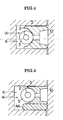
- the comparative example 1 (See FIG. 4 ) is a conventional combined oil ring 1A with a coil expander.
- the comparative example 2 (See FIG. 5 ) is a combined oil ring 1A with a side rail 4a on the lower side.
- the embodiment and the comparative example 2 utilized a side rail whose axial width is one-third that of the axial width of the oil ring.
- the oil consumption per unit of time in the combined oil ring of the present invention was improved by approximately 30 percent compared to the conventional combined oil ring of the comparative example 1.
- the improvement in the comparative example 2 was slight compared to the comparative example 1.
Landscapes
- Engineering & Computer Science (AREA)
- General Engineering & Computer Science (AREA)
- Mechanical Engineering (AREA)
- Pistons, Piston Rings, And Cylinders (AREA)
Claims (6)
- Zusammengesetzter Ölring (1), der Folgendes umfasst:einen Ölring (2), der einen ungefähr I-förmigen Querschnitt besitzt, der eine obere und eine untere Leiste (7, 8), die einstückig an einer äußeren Umfangsseite des Ölrings (2) geformt sind, um auf einer Zylinderwand (11) zu gleiten, und ein Netz (9), das die obere und die untere Leiste (7, 8) verbindet, enthält;ein Spulenexpander (3), der in einer inneren Umfangsnut (15), die von der oberen und der unteren Leiste (7, 8) und dem Netz (9) des Ölrings (2) gebildet wird, angebracht ist, um den Ölring (2) radial nach außen zu drängen; undeine Seitenleiste (4), die an einer oberen äußeren Seite des Ölrings (2) angebracht ist, wobei die radiale Dicke der Seitenleiste (4) größer ist als die radiale Dicke des Ölrings (2);dadurch gekennzeichnet, dass:die Seitenleiste (4) eine ringförmige flache Platte ist, die keine Torsion bzw. Windung entlang einer Achsenrichtung des Ölrings (2) besitzt; unddie Seitenleiste (4) eine kleinere Masse als der Ölring (2) besitzt und dass dann, wenn der Ölring in einem Zylinder (10) installiert ist, die Seitenleiste (4) im Vergleich zu dem Spulenexpander (3) eine kleinere nach außen wirkende Kraft auf die Oberfläche der Zylinderbohrung besitzt.
- Zusammengesetzter Ölring nach Anspruch 1, wobei sich Lücken (2a, 4a) des Ölrings (2) und der Seitenleiste (4) an Positionen, die voneinander entlang des Umfangs versetzt sind, befinden.
- Zusammengesetzter Ölring nach Anspruch 1 oder 2, wobei mindestens eine der Lücken (2a, 4a) des Ölrings (2) und der Seitenleiste (4) eine schräge Lücke entlang des Radius ist.
- Zusammengesetzter Ölring nach einem der Ansprüche 1 bis 3, wobei Lücken (2a, 4a) des Ölrings (2) und der Seitenleiste (4) schräge Lücken entlang des Radius sind und einander gegenüberliegend angeordnet sind.
- Zusammengesetzter Ölring nach einem der Ansprüche 1 bis 4, wobei dann, wenn der Ölring in einem Zylinder (10) installiert ist, die Seitenleiste (4) eine geringe radiale Druckkraft gegen die Zylinderwand (11) besitzt.
- Zusammengesetzter Ölring nach Anspruch 5, wobei die Seitenleiste (4) eine Lücke (4a) entlang des Radius umfasst, die Abmessungen von 0 < L1 - L2 ≤ 3 mm besitzt, wobei L1 die Lückenabmessung ist, während die Seitenleiste (4) in dem freien Zustand ist, und L2 die Lückenabmessung während eines Einbaus der Seitenleiste (4) ist.
Applications Claiming Priority (1)
| Application Number | Priority Date | Filing Date | Title |
|---|---|---|---|
| JP2008118240A JP5164659B2 (ja) | 2008-04-30 | 2008-04-30 | 組合せオイルリング |
Publications (2)
| Publication Number | Publication Date |
|---|---|
| EP2113690A1 EP2113690A1 (de) | 2009-11-04 |
| EP2113690B1 true EP2113690B1 (de) | 2014-04-23 |
Family
ID=40940497
Family Applications (1)
| Application Number | Title | Priority Date | Filing Date |
|---|---|---|---|
| EP09251112.0A Not-in-force EP2113690B1 (de) | 2008-04-30 | 2009-04-17 | Kombinierter Ölring |
Country Status (3)
| Country | Link |
|---|---|
| US (1) | US8616556B2 (de) |
| EP (1) | EP2113690B1 (de) |
| JP (1) | JP5164659B2 (de) |
Families Citing this family (4)
| Publication number | Priority date | Publication date | Assignee | Title |
|---|---|---|---|---|
| DE102011106656A1 (de) * | 2011-07-05 | 2013-01-10 | Mahle International Gmbh | Ölabstreifring für einen Kolben eines Verbrennungsmotors |
| JP6454523B2 (ja) * | 2014-11-26 | 2019-01-16 | 株式会社リケン | 上下方向判別用治具及び上下方向判別方法 |
| DE102017223084A1 (de) * | 2017-12-18 | 2019-06-19 | Volkswagen Aktiengesellschaft | Dreiteiliger Ölabstreifring mit einer in radialer Richtung nach außen wirkenden Feder, einem Ringkörper und einer Lamelle sowie Hubkolbenbrennkraftmaschine mit einem solchen Ölabstreifring |
| US12104551B1 (en) | 2024-01-30 | 2024-10-01 | Caterpillar Inc. | Piston having baffle ring for limiting abnormal combustion and piston and cylinder liner assembly |
Family Cites Families (17)
| Publication number | Priority date | Publication date | Assignee | Title |
|---|---|---|---|---|
| US2693398A (en) * | 1950-07-11 | 1954-11-02 | Hastings Mfg Co | Piston ring assembly and support member |
| US2656228A (en) * | 1951-02-12 | 1953-10-20 | Ramsey Corp | Piston packing ring |
| BE691635A (de) | 1966-01-27 | 1967-05-29 | ||
| US3831952A (en) * | 1967-02-17 | 1974-08-27 | Sealfire | Piston and piston rings unit for an internal combustion engine |
| FR1540312A (fr) * | 1967-02-17 | 1968-09-27 | Ensemble piston et segments pour moteur à combustion interne | |
| US3627333A (en) * | 1970-01-22 | 1971-12-14 | Eaton Yale & Towne | Piston ring |
| GB1489339A (en) | 1973-11-30 | 1977-10-19 | Rolls Royce | Gas turbine engine combustion chambers |
| US5618048A (en) * | 1988-03-24 | 1997-04-08 | Moriarty; Maurice J. | Piston ring seal having angled ends |
| JP2501754Y2 (ja) * | 1990-04-27 | 1996-06-19 | トヨタ自動車株式会社 | 内燃機関のピストンリング |
| JPH0488261A (ja) | 1990-07-31 | 1992-03-23 | Nippon Piston Ring Co Ltd | 組合せオイルリング |
| JPH05231540A (ja) | 1992-02-17 | 1993-09-07 | Nippon Piston Ring Co Ltd | 組合せオイルリング |
| US5564699A (en) * | 1995-02-15 | 1996-10-15 | Caterpillar Inc. | Side and gap sealed oil ring |
| DE19605457A1 (de) * | 1995-02-15 | 1996-08-22 | Caterpillar Inc | Seiten- und spaltengedichteter Ölring |
| JP4322500B2 (ja) * | 2002-12-18 | 2009-09-02 | 帝国ピストンリング株式会社 | 組合せオイルリング |
| US20060113730A1 (en) * | 2003-04-07 | 2006-06-01 | Takao Suzuki | Combination oil ring |
| JP2007009971A (ja) * | 2005-06-29 | 2007-01-18 | Toyota Motor Corp | ピストンリング |
| JP5094311B2 (ja) | 2007-09-28 | 2012-12-12 | 株式会社日立製作所 | 投射型映像表示装置 |
-
2008
- 2008-04-30 JP JP2008118240A patent/JP5164659B2/ja active Active
-
2009
- 2009-04-17 EP EP09251112.0A patent/EP2113690B1/de not_active Not-in-force
- 2009-04-21 US US12/427,228 patent/US8616556B2/en not_active Expired - Fee Related
Also Published As
| Publication number | Publication date |
|---|---|
| JP5164659B2 (ja) | 2013-03-21 |
| US20090273142A1 (en) | 2009-11-05 |
| EP2113690A1 (de) | 2009-11-04 |
| JP2009264349A (ja) | 2009-11-12 |
| US8616556B2 (en) | 2013-12-31 |
Similar Documents
| Publication | Publication Date | Title |
|---|---|---|
| EP1927794A1 (de) | Kombinierter Ölring | |
| EP1431630B1 (de) | Zusammengesetzter Ölring | |
| KR20090035413A (ko) | 왕복운동 기관의 피스톤 링 | |
| US20150184748A1 (en) | Oil control ring assembly | |
| EP3043054B1 (de) | Ring für eine zylinderlaufbuchse | |
| EP2017506B1 (de) | Kombination aus einem Kolben und einem Kolbenring | |
| US8616556B2 (en) | Combined oil ring | |
| CN117006245A (zh) | 组合油环 | |
| US9163725B2 (en) | Oil control ring with ferrous body less than 2.0 millimeters high for internal combustion engines | |
| US7494129B2 (en) | Piston ring | |
| US5794941A (en) | Piston ring assembly | |
| CA2924575C (en) | Dual pre-load cylindrical seal | |
| US11982357B2 (en) | Cylinder of an internal combustion engine | |
| CN101253352A (zh) | 用于内燃机的控油环 | |
| JP2005264978A (ja) | 圧力リング | |
| CN107002872A (zh) | 油环 | |
| EP3388717B1 (de) | Kolben mit kolbenringe | |
| WO2015132112A1 (en) | Oil control ring assembly | |
| JP6010278B2 (ja) | ディーゼルエンジン用ピストンリングの組合せ | |
| JP6718228B2 (ja) | 内燃機関用ピストンとオイルリングの組合せ | |
| US8876115B2 (en) | Three-piece oil-control ring for an internal combustion engine | |
| US12305763B2 (en) | Piston ring with variable pressure relief | |
| WO2024084184A1 (en) | Sliding ring seal assembly | |
| JPH05133472A (ja) | 内燃機関のコンプレツシヨンリング装置 |
Legal Events
| Date | Code | Title | Description |
|---|---|---|---|
| PUAI | Public reference made under article 153(3) epc to a published international application that has entered the european phase |
Free format text: ORIGINAL CODE: 0009012 |
|
| AK | Designated contracting states |
Kind code of ref document: A1 Designated state(s): AT BE BG CH CY CZ DE DK EE ES FI FR GB GR HR HU IE IS IT LI LT LU LV MC MK MT NL NO PL PT RO SE SI SK TR |
|
| 17P | Request for examination filed |
Effective date: 20100428 |
|
| 17Q | First examination report despatched |
Effective date: 20101109 |
|
| GRAP | Despatch of communication of intention to grant a patent |
Free format text: ORIGINAL CODE: EPIDOSNIGR1 |
|
| INTG | Intention to grant announced |
Effective date: 20140122 |
|
| GRAS | Grant fee paid |
Free format text: ORIGINAL CODE: EPIDOSNIGR3 |
|
| GRAA | (expected) grant |
Free format text: ORIGINAL CODE: 0009210 |
|
| AK | Designated contracting states |
Kind code of ref document: B1 Designated state(s): AT BE BG CH CY CZ DE DK EE ES FI FR GB GR HR HU IE IS IT LI LT LU LV MC MK MT NL NO PL PT RO SE SI SK TR |
|
| REG | Reference to a national code |
Ref country code: GB Ref legal event code: FG4D |
|
| REG | Reference to a national code |
Ref country code: CH Ref legal event code: EP |
|
| REG | Reference to a national code |
Ref country code: AT Ref legal event code: REF Ref document number: 664061 Country of ref document: AT Kind code of ref document: T Effective date: 20140515 |
|
| REG | Reference to a national code |
Ref country code: IE Ref legal event code: FG4D |
|
| REG | Reference to a national code |
Ref country code: DE Ref legal event code: R096 Ref document number: 602009023437 Country of ref document: DE Effective date: 20140605 |
|
| REG | Reference to a national code |
Ref country code: AT Ref legal event code: MK05 Ref document number: 664061 Country of ref document: AT Kind code of ref document: T Effective date: 20140423 |
|
| REG | Reference to a national code |
Ref country code: NL Ref legal event code: VDEP Effective date: 20140423 |
|
| REG | Reference to a national code |
Ref country code: LT Ref legal event code: MG4D |
|
| PG25 | Lapsed in a contracting state [announced via postgrant information from national office to epo] |
Ref country code: GR Free format text: LAPSE BECAUSE OF FAILURE TO SUBMIT A TRANSLATION OF THE DESCRIPTION OR TO PAY THE FEE WITHIN THE PRESCRIBED TIME-LIMIT Effective date: 20140724 Ref country code: NL Free format text: LAPSE BECAUSE OF FAILURE TO SUBMIT A TRANSLATION OF THE DESCRIPTION OR TO PAY THE FEE WITHIN THE PRESCRIBED TIME-LIMIT Effective date: 20140423 Ref country code: BG Free format text: LAPSE BECAUSE OF FAILURE TO SUBMIT A TRANSLATION OF THE DESCRIPTION OR TO PAY THE FEE WITHIN THE PRESCRIBED TIME-LIMIT Effective date: 20140723 Ref country code: CY Free format text: LAPSE BECAUSE OF FAILURE TO SUBMIT A TRANSLATION OF THE DESCRIPTION OR TO PAY THE FEE WITHIN THE PRESCRIBED TIME-LIMIT Effective date: 20140423 Ref country code: FI Free format text: LAPSE BECAUSE OF FAILURE TO SUBMIT A TRANSLATION OF THE DESCRIPTION OR TO PAY THE FEE WITHIN THE PRESCRIBED TIME-LIMIT Effective date: 20140423 Ref country code: IS Free format text: LAPSE BECAUSE OF FAILURE TO SUBMIT A TRANSLATION OF THE DESCRIPTION OR TO PAY THE FEE WITHIN THE PRESCRIBED TIME-LIMIT Effective date: 20140823 Ref country code: LT Free format text: LAPSE BECAUSE OF FAILURE TO SUBMIT A TRANSLATION OF THE DESCRIPTION OR TO PAY THE FEE WITHIN THE PRESCRIBED TIME-LIMIT Effective date: 20140423 Ref country code: NO Free format text: LAPSE BECAUSE OF FAILURE TO SUBMIT A TRANSLATION OF THE DESCRIPTION OR TO PAY THE FEE WITHIN THE PRESCRIBED TIME-LIMIT Effective date: 20140723 |
|
| PG25 | Lapsed in a contracting state [announced via postgrant information from national office to epo] |
Ref country code: AT Free format text: LAPSE BECAUSE OF FAILURE TO SUBMIT A TRANSLATION OF THE DESCRIPTION OR TO PAY THE FEE WITHIN THE PRESCRIBED TIME-LIMIT Effective date: 20140423 Ref country code: HR Free format text: LAPSE BECAUSE OF FAILURE TO SUBMIT A TRANSLATION OF THE DESCRIPTION OR TO PAY THE FEE WITHIN THE PRESCRIBED TIME-LIMIT Effective date: 20140423 Ref country code: PL Free format text: LAPSE BECAUSE OF FAILURE TO SUBMIT A TRANSLATION OF THE DESCRIPTION OR TO PAY THE FEE WITHIN THE PRESCRIBED TIME-LIMIT Effective date: 20140423 Ref country code: SE Free format text: LAPSE BECAUSE OF FAILURE TO SUBMIT A TRANSLATION OF THE DESCRIPTION OR TO PAY THE FEE WITHIN THE PRESCRIBED TIME-LIMIT Effective date: 20140423 Ref country code: ES Free format text: LAPSE BECAUSE OF FAILURE TO SUBMIT A TRANSLATION OF THE DESCRIPTION OR TO PAY THE FEE WITHIN THE PRESCRIBED TIME-LIMIT Effective date: 20140423 Ref country code: LV Free format text: LAPSE BECAUSE OF FAILURE TO SUBMIT A TRANSLATION OF THE DESCRIPTION OR TO PAY THE FEE WITHIN THE PRESCRIBED TIME-LIMIT Effective date: 20140423 |
|
| PG25 | Lapsed in a contracting state [announced via postgrant information from national office to epo] |
Ref country code: PT Free format text: LAPSE BECAUSE OF FAILURE TO SUBMIT A TRANSLATION OF THE DESCRIPTION OR TO PAY THE FEE WITHIN THE PRESCRIBED TIME-LIMIT Effective date: 20140825 |
|
| REG | Reference to a national code |
Ref country code: DE Ref legal event code: R097 Ref document number: 602009023437 Country of ref document: DE |
|
| PG25 | Lapsed in a contracting state [announced via postgrant information from national office to epo] |
Ref country code: RO Free format text: LAPSE BECAUSE OF FAILURE TO SUBMIT A TRANSLATION OF THE DESCRIPTION OR TO PAY THE FEE WITHIN THE PRESCRIBED TIME-LIMIT Effective date: 20140423 Ref country code: BE Free format text: LAPSE BECAUSE OF FAILURE TO SUBMIT A TRANSLATION OF THE DESCRIPTION OR TO PAY THE FEE WITHIN THE PRESCRIBED TIME-LIMIT Effective date: 20140423 Ref country code: CZ Free format text: LAPSE BECAUSE OF FAILURE TO SUBMIT A TRANSLATION OF THE DESCRIPTION OR TO PAY THE FEE WITHIN THE PRESCRIBED TIME-LIMIT Effective date: 20140423 Ref country code: DK Free format text: LAPSE BECAUSE OF FAILURE TO SUBMIT A TRANSLATION OF THE DESCRIPTION OR TO PAY THE FEE WITHIN THE PRESCRIBED TIME-LIMIT Effective date: 20140423 Ref country code: EE Free format text: LAPSE BECAUSE OF FAILURE TO SUBMIT A TRANSLATION OF THE DESCRIPTION OR TO PAY THE FEE WITHIN THE PRESCRIBED TIME-LIMIT Effective date: 20140423 Ref country code: SK Free format text: LAPSE BECAUSE OF FAILURE TO SUBMIT A TRANSLATION OF THE DESCRIPTION OR TO PAY THE FEE WITHIN THE PRESCRIBED TIME-LIMIT Effective date: 20140423 |
|
| PLBE | No opposition filed within time limit |
Free format text: ORIGINAL CODE: 0009261 |
|
| STAA | Information on the status of an ep patent application or granted ep patent |
Free format text: STATUS: NO OPPOSITION FILED WITHIN TIME LIMIT |
|
| REG | Reference to a national code |
Ref country code: DE Ref legal event code: R082 Ref document number: 602009023437 Country of ref document: DE Representative=s name: DEHNS, GB |
|
| PG25 | Lapsed in a contracting state [announced via postgrant information from national office to epo] |
Ref country code: IT Free format text: LAPSE BECAUSE OF FAILURE TO SUBMIT A TRANSLATION OF THE DESCRIPTION OR TO PAY THE FEE WITHIN THE PRESCRIBED TIME-LIMIT Effective date: 20140423 |
|
| 26N | No opposition filed |
Effective date: 20150126 |
|
| REG | Reference to a national code |
Ref country code: DE Ref legal event code: R081 Ref document number: 602009023437 Country of ref document: DE Owner name: TPR CO., LTD., JP Free format text: FORMER OWNER: TEIKOKU PISTON RING CO., LTD., TOKYO, JP Effective date: 20150320 Ref country code: DE Ref legal event code: R082 Ref document number: 602009023437 Country of ref document: DE Representative=s name: DEHNS, GB Effective date: 20150320 |
|
| REG | Reference to a national code |
Ref country code: DE Ref legal event code: R097 Ref document number: 602009023437 Country of ref document: DE Effective date: 20150126 |
|
| PG25 | Lapsed in a contracting state [announced via postgrant information from national office to epo] |
Ref country code: SI Free format text: LAPSE BECAUSE OF FAILURE TO SUBMIT A TRANSLATION OF THE DESCRIPTION OR TO PAY THE FEE WITHIN THE PRESCRIBED TIME-LIMIT Effective date: 20140423 |
|
| PG25 | Lapsed in a contracting state [announced via postgrant information from national office to epo] |
Ref country code: MC Free format text: LAPSE BECAUSE OF FAILURE TO SUBMIT A TRANSLATION OF THE DESCRIPTION OR TO PAY THE FEE WITHIN THE PRESCRIBED TIME-LIMIT Effective date: 20140423 Ref country code: LU Free format text: LAPSE BECAUSE OF FAILURE TO SUBMIT A TRANSLATION OF THE DESCRIPTION OR TO PAY THE FEE WITHIN THE PRESCRIBED TIME-LIMIT Effective date: 20150417 |
|
| REG | Reference to a national code |
Ref country code: CH Ref legal event code: PL |
|
| GBPC | Gb: european patent ceased through non-payment of renewal fee |
Effective date: 20150417 |
|
| REG | Reference to a national code |
Ref country code: IE Ref legal event code: MM4A |
|
| PG25 | Lapsed in a contracting state [announced via postgrant information from national office to epo] |
Ref country code: GB Free format text: LAPSE BECAUSE OF NON-PAYMENT OF DUE FEES Effective date: 20150417 Ref country code: CH Free format text: LAPSE BECAUSE OF NON-PAYMENT OF DUE FEES Effective date: 20150430 Ref country code: LI Free format text: LAPSE BECAUSE OF NON-PAYMENT OF DUE FEES Effective date: 20150430 |
|
| REG | Reference to a national code |
Ref country code: FR Ref legal event code: ST Effective date: 20151231 |
|
| PG25 | Lapsed in a contracting state [announced via postgrant information from national office to epo] |
Ref country code: FR Free format text: LAPSE BECAUSE OF NON-PAYMENT OF DUE FEES Effective date: 20150430 |
|
| PG25 | Lapsed in a contracting state [announced via postgrant information from national office to epo] |
Ref country code: IE Free format text: LAPSE BECAUSE OF NON-PAYMENT OF DUE FEES Effective date: 20150417 |
|
| PGFP | Annual fee paid to national office [announced via postgrant information from national office to epo] |
Ref country code: DE Payment date: 20160421 Year of fee payment: 8 |
|
| PG25 | Lapsed in a contracting state [announced via postgrant information from national office to epo] |
Ref country code: MT Free format text: LAPSE BECAUSE OF FAILURE TO SUBMIT A TRANSLATION OF THE DESCRIPTION OR TO PAY THE FEE WITHIN THE PRESCRIBED TIME-LIMIT Effective date: 20140423 |
|
| PG25 | Lapsed in a contracting state [announced via postgrant information from national office to epo] |
Ref country code: HU Free format text: LAPSE BECAUSE OF FAILURE TO SUBMIT A TRANSLATION OF THE DESCRIPTION OR TO PAY THE FEE WITHIN THE PRESCRIBED TIME-LIMIT; INVALID AB INITIO Effective date: 20090417 |
|
| PG25 | Lapsed in a contracting state [announced via postgrant information from national office to epo] |
Ref country code: TR Free format text: LAPSE BECAUSE OF FAILURE TO SUBMIT A TRANSLATION OF THE DESCRIPTION OR TO PAY THE FEE WITHIN THE PRESCRIBED TIME-LIMIT Effective date: 20140423 |
|
| REG | Reference to a national code |
Ref country code: DE Ref legal event code: R119 Ref document number: 602009023437 Country of ref document: DE |
|
| PG25 | Lapsed in a contracting state [announced via postgrant information from national office to epo] |
Ref country code: DE Free format text: LAPSE BECAUSE OF NON-PAYMENT OF DUE FEES Effective date: 20171103 |
|
| PG25 | Lapsed in a contracting state [announced via postgrant information from national office to epo] |
Ref country code: MK Free format text: LAPSE BECAUSE OF FAILURE TO SUBMIT A TRANSLATION OF THE DESCRIPTION OR TO PAY THE FEE WITHIN THE PRESCRIBED TIME-LIMIT Effective date: 20140423 |