EP2113691A2 - Vannes papillon - Google Patents
Vannes papillon Download PDFInfo
- Publication number
- EP2113691A2 EP2113691A2 EP20080173074 EP08173074A EP2113691A2 EP 2113691 A2 EP2113691 A2 EP 2113691A2 EP 20080173074 EP20080173074 EP 20080173074 EP 08173074 A EP08173074 A EP 08173074A EP 2113691 A2 EP2113691 A2 EP 2113691A2
- Authority
- EP
- European Patent Office
- Prior art keywords
- disk
- seal
- annular seal
- temperature
- butterfly valve
- Prior art date
- Legal status (The legal status is an assumption and is not a legal conclusion. Google has not performed a legal analysis and makes no representation as to the accuracy of the status listed.)
- Granted
Links
- 239000000463 material Substances 0.000 claims abstract description 67
- 230000015556 catabolic process Effects 0.000 claims abstract description 40
- 238000001816 cooling Methods 0.000 claims abstract description 38
- 238000007789 sealing Methods 0.000 claims abstract description 25
- 239000012809 cooling fluid Substances 0.000 claims description 16
- 229920001971 elastomer Polymers 0.000 claims description 13
- 239000000806 elastomer Substances 0.000 claims description 13
- 230000002093 peripheral effect Effects 0.000 claims description 10
- 239000002184 metal Substances 0.000 claims description 6
- 229910052751 metal Inorganic materials 0.000 claims description 6
- 238000000034 method Methods 0.000 claims description 6
- 230000013011 mating Effects 0.000 claims 1
- 230000002401 inhibitory effect Effects 0.000 abstract description 2
- 239000012530 fluid Substances 0.000 description 7
- 150000002739 metals Chemical class 0.000 description 4
- 238000012546 transfer Methods 0.000 description 4
- 238000003466 welding Methods 0.000 description 3
- 238000004891 communication Methods 0.000 description 2
- 230000015572 biosynthetic process Effects 0.000 description 1
- 239000004020 conductor Substances 0.000 description 1
- 238000010276 construction Methods 0.000 description 1
- 230000006866 deterioration Effects 0.000 description 1
- 238000011161 development Methods 0.000 description 1
- 230000009977 dual effect Effects 0.000 description 1
- 230000000694 effects Effects 0.000 description 1
- 230000002035 prolonged effect Effects 0.000 description 1
- 238000011160 research Methods 0.000 description 1
- 229910001220 stainless steel Inorganic materials 0.000 description 1
- 239000010935 stainless steel Substances 0.000 description 1
Images


Classifications
-
- F—MECHANICAL ENGINEERING; LIGHTING; HEATING; WEAPONS; BLASTING
- F16—ENGINEERING ELEMENTS AND UNITS; GENERAL MEASURES FOR PRODUCING AND MAINTAINING EFFECTIVE FUNCTIONING OF MACHINES OR INSTALLATIONS; THERMAL INSULATION IN GENERAL
- F16K—VALVES; TAPS; COCKS; ACTUATING-FLOATS; DEVICES FOR VENTING OR AERATING
- F16K1/00—Lift valves or globe valves, i.e. cut-off apparatus with closure members having at least a component of their opening and closing motion perpendicular to the closing faces
- F16K1/16—Lift valves or globe valves, i.e. cut-off apparatus with closure members having at least a component of their opening and closing motion perpendicular to the closing faces with pivoted closure-members
- F16K1/18—Lift valves or globe valves, i.e. cut-off apparatus with closure members having at least a component of their opening and closing motion perpendicular to the closing faces with pivoted closure-members with pivoted discs or flaps
- F16K1/22—Lift valves or globe valves, i.e. cut-off apparatus with closure members having at least a component of their opening and closing motion perpendicular to the closing faces with pivoted closure-members with pivoted discs or flaps with axis of rotation crossing the valve member, e.g. butterfly valves
- F16K1/226—Shaping or arrangements of the sealing
- F16K1/2263—Shaping or arrangements of the sealing the sealing being arranged on the valve seat
- F16K1/2265—Shaping or arrangements of the sealing the sealing being arranged on the valve seat with a channel- or U-shaped seal covering a central body portion
-
- F—MECHANICAL ENGINEERING; LIGHTING; HEATING; WEAPONS; BLASTING
- F16—ENGINEERING ELEMENTS AND UNITS; GENERAL MEASURES FOR PRODUCING AND MAINTAINING EFFECTIVE FUNCTIONING OF MACHINES OR INSTALLATIONS; THERMAL INSULATION IN GENERAL
- F16K—VALVES; TAPS; COCKS; ACTUATING-FLOATS; DEVICES FOR VENTING OR AERATING
- F16K49/00—Means in or on valves for heating or cooling
- F16K49/005—Circulation means for a separate heat transfer fluid
- F16K49/007—Circulation means for a separate heat transfer fluid located within the obturating element
-
- Y—GENERAL TAGGING OF NEW TECHNOLOGICAL DEVELOPMENTS; GENERAL TAGGING OF CROSS-SECTIONAL TECHNOLOGIES SPANNING OVER SEVERAL SECTIONS OF THE IPC; TECHNICAL SUBJECTS COVERED BY FORMER USPC CROSS-REFERENCE ART COLLECTIONS [XRACs] AND DIGESTS
- Y10—TECHNICAL SUBJECTS COVERED BY FORMER USPC
- Y10T—TECHNICAL SUBJECTS COVERED BY FORMER US CLASSIFICATION
- Y10T137/00—Fluid handling
- Y10T137/0318—Processes
-
- Y—GENERAL TAGGING OF NEW TECHNOLOGICAL DEVELOPMENTS; GENERAL TAGGING OF CROSS-SECTIONAL TECHNOLOGIES SPANNING OVER SEVERAL SECTIONS OF THE IPC; TECHNICAL SUBJECTS COVERED BY FORMER USPC CROSS-REFERENCE ART COLLECTIONS [XRACs] AND DIGESTS
- Y10—TECHNICAL SUBJECTS COVERED BY FORMER USPC
- Y10T—TECHNICAL SUBJECTS COVERED BY FORMER US CLASSIFICATION
- Y10T137/00—Fluid handling
- Y10T137/4238—With cleaner, lubrication added to fluid or liquid sealing at valve interface
- Y10T137/4245—Cleaning or steam sterilizing
- Y10T137/4259—With separate material addition
Definitions
- This invention relates generally to butterfly valves and, more specifically, to butterfly valves for use with hot materials
- the elastomer seal is deflated and the disk is pivoted from the closed position to an open position.
- the seals used in the butterfly valves are generally elastomers which have a low breakdown temperature. Often times the breakdown temperature of the elastomer seal is below the temperature of the material being transported. An exposure of the elastomer seal to high temperature materials, even if limited, can cause failure of the seal. Consequently, butterfly valve are used for handling materials that are at temperatures below the breakdown temperature of the elastomer seal to in order to avoid seal failure.
- a butterfly valve for handling materials where the temperature of the materials flowing though the butterfly valve can exceed the breakdown temperature of the sealing member with the butterfly valve inhibiting contact of hot transportable materials with the sealing member to isolate the hot transportable materials from the sealing member.
- Cooling conduits maintain at least portions of the valve that contacts the sealing member at a temperature below the breakdown temperature of the sealing member to prevent seal failure.
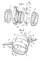
- FIG 1 is an exploded view of a high temperature butterfly valve 10 that can handle materials that may exceed the breakdown temperature of a seal in valve 10.
- butterfly valves have annular seals, which are made from elastomers, that can expand to seal the valve and contract to allow the valve to open or close
- Valve 10 includes an inlet collar 12, a housing 11, an inflatable annular seal 15, a rotateable disk 14 and an outlet collar 13.
- Inlet collar 12 and outlet collar 13 typically connect to a conduit, such as a pneumatic conduit, to direct the flow of materials through the butterfly valve 10.
- the disk 14 is pivotable about a spindle axis 14a to enable the disk 14 to be opened and closed. If disk 14 extends transverse to the conduit, as illustrated in Figure 1 , it prevents flow of materials through the valve 10.
- disk 14 is pivoted 90 degrees about axis 14a the disk 14 is an open position with the disk parallel to a central axis of collars 13 and 14 to allow material to flow through the valve 10.
- the components of the valve 14, with the exception of the seals, are generally made of metals to withstand the forces and the temperatures of the materials that may contact the valve.
- the annular seal 15, which is required to expand to seal the valve and contract to unseal the valve, are typically made from materials such as elastomers that breakdown at a few hundred degrees.
- An example of an elastomer seal that expands and contract to seal and unseal a butterfly valve is shown in Steele U.S. patent 4,836,499 .
- FIG 2 is an exploded view of disk 14 of the high temperature butterfly valve 10 of Figure 1 .
- Disk 14 includes a massive central disk member 20 and a rim 21 that fits on the peripheral face 20a of central disk member 20. Located on the interior of rim 21 are three rings, an outer rib or ring 24, a central rib or ring 23 and an outer rib or ring 22.
- a first annular cooling channel 21b is located between outer ring 24 and central ring 23.
- an annular cooling channel 21 a is located between central ring 24 and outer ring 22.
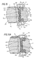
- FIG. 8 The position of the cooling conduits 21a and 21b with respect to central disk member 20 and annular seal 15 is shown in Figure 8 as the central member 20 and rim 21 coact to form two peripherally cooling conduits which have an annular configuration and with an elongated cross section.
- the rim 21 and central member are secured to each other to maintain the rim 21 in fixed position on central member 20, for example rim 21 may be secured thereto by welding or the like.
- disk 14 includes a first hollow shaft 25 with a hub 28 extending outward from one end of central disk member 20 and a second hollow shaft 24 having a hub 27 extending outward from an opposite end of' central disk member 20 with the shafts 24 and 25 located diametrically opposite from each other.
- Shafts 24 and 25 provide a dual purpose, first they allow one to rotate disk 14, about axis 14a, from the closed position to the open position and vice versa. In addition, both shafts permit the axial flow of a cooling fluid threrethrough When assemble the hub 28 fits in rim 21 with conduit 25b in fluid communication with passage 20d and conduit 25c in fluid communication with passage 20c.
- shafts 24 and 25 may be affixed to rim 21 by welding or the like.
- disk member 20 may also be affixed to rim 21 by welding to form a disk 14 of unitary construction.
- Figure 2 shows the flow passages in shaft 25 allows a cooling fluid to be delivered into the annular cooling conduits 21b and 21 a in periphery of disk 14, which are formed by disk surface 20a and cooling channels 21a and 21b.
- a reference to Figure 9 shows an isolated sectional view of the shaft 25 located in housing 11 with a central passage 25d that directs a cooling fluid, indicated by arrows through the fluid passage 25b and 25c into the annular cooling channel 21a and the annular cooling channel 21b.
- the fluid passages are located on both sides of shaft 23 so that cooling fluid can flow in opposite directions into peripheral disk cooling channels 21a and 21b.
- a cooling fluid can be directed to the rim 21 of the disk 14 to maintain the rim surface 21d of rim 21 at a temperature that is less than the breakdown temperature of the annular seal 15.
- Figure 9 shows the annular seal 15 with shaft 25 extending threrethrough and the annular seal 15 proximate the peripheral surface 21 d of rim 21.
- a further feature of the invention is that one or multiple features may be used to limit or inhibit the heat transfer from hot materials, which are controlled by the butterfly valve 10, to the annular seal 15 wherein the hot materials are at temperatures that could cause breakdown of the annular seal.
- hot materials which are controlled by the butterfly valve 10
- the seal 15 may soften, erode or otherwise fail so that the disk 14 can not be properly sealed to prevent passage of materials therepast.
- disk cooling may be incorporated into a butterfly valve to inhibit seal deterioration when the materials handled by the butterfly valve exceed a breakdown temperature of the annular seal
- a breakdown temperature of the annular seal In some cases where the temperature of the hot materials is near or at the breakdown temperature of the annular seal only one of the features may be used, for example disk cooling, and more specifically cooling of' the disk parts such as the rim that come into contact with the annular seal. In other cases when the temperature of the hot materials greatly exceeds the breakdown temperature of the annular seal multiple features described herein may be used. In still other cases one may want to use all or selected features of the invention to ensure that the annular seal is inhibited from breakdown.
- the rings 22, 23 and 24 can be made narrow in relation to the width of the disk 20 as illustrated in Figure 8 thus minimizing the heat sink effect of the massive central disk member 20 by limiting a heat conduction path from the central disk member to the rim 21, which are a metal, for example stainless steel.
- metals are described for formation of central member 20 and rim 21 other materials may be used, particularly if the hot transportable materials are corrosive to metals.
- FIG 10 shows an isolated view of the inflatable annular seal 15 taken along lines 10-10 of Figure 1 showing annular lobes 15a and 15b that can engage the housing 11 as illustrated in Figure 8A and a shaft opening 15h.
- the annular seal 15 contains a curved disk sealing surface 15c having a radius of curvature R 2 that extends from central axis 15e.
- the radius of curvature of the sealing member surface 15c which is measured from the central axis 15e to the outer surface 15c, is similar or identical to the radius of curvature R 1 , (see Figure 7 and Figure 8 ) of disk 14.
- the similar or identical radius of curvatures allows the gap D 1 (see Figure 8 ) between the annular sealing ring 20 and the peripheral of disk 14, which allows pivoting disk 14 from the open position to the closed position, to be minimized to thereby inhibit or prevent hot materials coming into contact with the annular seal 15 when the disk 14 is in the closed position as shown in Figure 8A .
- By minimizing clearance D 1 between annular seal 15 and the disk 14 one can inhibit hot materials from contacting the annular seal 15 when the butterfly valve is in the closed condition since the annular seal has a limited exposure to hot materials 9 that can cause breakdown of the annular seal 15 due to the temperatures of the hot materials exceeding the breakdown temperature of the annular seal 15.
- a further feature that one may use to inhibit temperature breakdown of the annular seal 15 is to incorporate close tolerances, usually a few thousands of an inch for example less than 010 inches, between the annular seal sealing surface15c and the disk periphery surface 21 d to limit travel of the sealing surface 15c and thus limit the opportunity for the hot material to contact the annular seal 15 when in the expanded or sealed condition.
- Figure 8 illustrates the close tolerance D 1 between surface 21a and sealing surface 15c on annular seal 15.
- the clearance is sufficiently large so as not to bind or hinder the opening and closing of disk 14 but sufficiently small so as to limit the ingress of hot materials into contact with the annular seal 15.
- a few thousands of an inch clearance is sufficient when the radius of curvature of the disk and the seal are identical or substantially equal.
- a further feature which may be used to inhibit heat transfer to the annular seal 15 includes having the width W 1 of disk 14 greater than the width W 2 of the annular seal 15 as illustrated in Figure 8A thus limiting the potential contact of the hot materials 9 with the annular seal 15 As a consequence the exposure of the annular seal 15 to hot materials is limited since lateral contact with the annular seal is the primary means for hot materials to contact annular seal 15 and hence the opportunity for breakdown of the annular seal 15 is inhibited or prevented.
- a further feature which may to used further inhibit breakdown of seal 15 is sealing member cooling and housing cooling, for example Figure 8 shows, a first cooling conduit 41 is located on a lateral annular face 15b of annular seal 15 and a second cooling conduit 40 is located on lateral face 15c of annular seal 15.
- Conduit 40 is formed by housing 11 and an annular heat conducting flange 45.
- conduit 41 is formed by housing 11 and an annular heat conducting flange 46. While elastomers breakdown at temperature considerably less than the temperatures which metals can withstand they are also poor heat conductors.
- the heat transfer between hot materials in the butterfly valve 10 and the annular seal 15 may be minimized through limiting the contact area of the annular seal 15 to the hot materials as well as through cooling valve components that come into contact with the annular seal 15. That is, by cooling valve components that come into direct contact with the annular seal 15 to temperatures which are below the breakdown temperature of the annular seal 15 one can further enhance the ability of the butterfly valve 10 to handle hot materials which may exceed the breakdown temperature of' the annular seal.
- Figure 8A shows the annular seal 15 in the sealed condition with chamber 50 pressurized thereby causing a seal surface 15c on annular seal 15 to contact surface 21 d on rim 21 to form a bubble tight seal therebetween.
- the above features to inhibit temperature breakdown of the annular seal 15 may be combined, for example by having disk 14 wider than the annular seal 15 and simultaneously cooling the disk 20 and the annular seal 15 through the cooling passages located proximate thereto which can assist in maintaining the temperature of the annular seal 15 below the breakdown temperature of the annular seal.
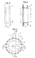
- Figure 3 shows collar 13 having a face plate 13a for attachment to a conduit and a face plate 13b for attachment to the housing 11 of butterfly valve 10.
- Figure 4 is a cross section view of collar 13 showing the inlet has a diameter D 4 and the outlet a diameter D 2 with the diameter D 2 greater than the diameter D 4 .
- Figure 5 shows an end view of butterfly valve with collar 13 opening having a diameter D 4 and a disk 14 located therein.
- hot transportable materials can flow on both sides of disk 14 in a straight flow path since the annular seal 15 is radially offset and therefore impingement with annular seal 15 is inhibited.
- FIG. 7 shows a cross section view of collar 13 and collar 14 attached to housing 11.
- Collar 13 which has an inlet diameter D 4 , which mates with the diameter of a conduit that delivers hot materials to butterfly valve 10, has an outlet diameter D 2 which is larger than inlet diameter D 4 .
- the internal diameter of collar 13 expands to a diameter D 2 at the disk 14 and reduces to a diameter D 4 at the second collar 14to also mate with the conduit that receives the hot materials from the butterfly valve 10.
- the annular seal 15 has a diameter D 3 which is greater than D 2 .
- the annular seal 15 is radially offset from a straight line flow path through the valve 10 to further inhibit hot transportable materials from contacting the annular seal 15 as materials flows through the butterfly valve 10. That is, when the disk 14 is in the open condition the hot materials, which generally contain mass and sufficient momentum to inhibit radial outflow toward the elastomer seal 15 thus further inhibit direct contact and heat transfer from the hot materials to the annular seal 15.
- annular seal 15 has been described herein other shapes of seals may be used with the shut off the valve to inhibit and prevent breakdown of the seal if the material being handle has a temperature that is above the breakdown temperature of the seal.
- the invention further includes a method of intermittent delivery of hot conduit transportable materials though a valve 14 that includes portions of the valve that have a breakdown temperature that is less than the temperature of the transportable materials comprising the steps of: pivoting a disk 14 to a closed condition; expanding an expandable seal 15 until the expandable seal contacts only a portion of a rim 20 of the disk; directing a cooling fluid through at least one cooling conduit 21a, 21b in the rim 20 of the disk 14 to maintain the temperature of the portion of the rim that contacts the expandable seal 15 at a temperature that is below a breakdown temperature of the expandable seal.
- One can also including a step of directing a cooling fluid through a housing supporting the expandable seal.
- One can contract the expandable seal 15 and pivot the disk 14 to an open condition.
- the method can include the step of directing a transportable material through housing 11 with the transportable material having sufficient momentum so as to inhibit or prevent bringing the transportable material from coming into contact with the expandable seal 15.
- the cooling fluid may be directed into a first shaft 25 and out a second shaft 24 with the first and second shaft located diametrically opposite from each other.
Landscapes
- Engineering & Computer Science (AREA)
- General Engineering & Computer Science (AREA)
- Mechanical Engineering (AREA)
- Physics & Mathematics (AREA)
- Thermal Sciences (AREA)
- Lift Valve (AREA)
- Details Of Valves (AREA)
Applications Claiming Priority (1)
| Application Number | Priority Date | Filing Date | Title |
|---|---|---|---|
| US12/150,715 US8256448B2 (en) | 2008-04-30 | 2008-04-30 | High temperature butterfly valves |
Publications (3)
| Publication Number | Publication Date |
|---|---|
| EP2113691A2 true EP2113691A2 (fr) | 2009-11-04 |
| EP2113691A3 EP2113691A3 (fr) | 2012-09-05 |
| EP2113691B1 EP2113691B1 (fr) | 2017-04-19 |
Family
ID=40940392
Family Applications (1)
| Application Number | Title | Priority Date | Filing Date |
|---|---|---|---|
| EP08173074.9A Not-in-force EP2113691B1 (fr) | 2008-04-30 | 2008-12-30 | Vannes papillon |
Country Status (3)
| Country | Link |
|---|---|
| US (2) | US8256448B2 (fr) |
| EP (1) | EP2113691B1 (fr) |
| BR (1) | BRPI0805007A2 (fr) |
Families Citing this family (8)
| Publication number | Priority date | Publication date | Assignee | Title |
|---|---|---|---|---|
| US9133960B2 (en) * | 2013-01-29 | 2015-09-15 | Mks Instruments, Inc. | Fluid control valves |
| US9228661B2 (en) | 2013-04-03 | 2016-01-05 | Dynamic Air Inc | Butterfly valve |
| US9650206B2 (en) * | 2015-07-24 | 2017-05-16 | Dynamic Aur Inc. | Conveying systems |
| TWI658224B (zh) | 2016-06-24 | 2019-05-01 | 美商亞根科技股份有限公司Dba克利米特 | 用於充氣/洩氣的閥 |
| US10107417B2 (en) * | 2016-12-14 | 2018-10-23 | Fisher Controls International Llc | Single-piece valve closure members having integral flow paths formed via additive manufacturing |
| CA3054860A1 (fr) | 2017-03-03 | 2018-09-07 | Swagelok Company | Composants de systeme de fluide dotes de passages de conditionnement thermique |
| US11085546B2 (en) | 2018-04-10 | 2021-08-10 | Fisher Controls International Llc | Purge apparatus for use with fluid valves |
| USD886237S1 (en) | 2018-09-04 | 2020-06-02 | Swagelok Company | Thermal trace valve body |
Citations (2)
| Publication number | Priority date | Publication date | Assignee | Title |
|---|---|---|---|---|
| US4836499A (en) | 1987-09-14 | 1989-06-06 | Dynamic Air Inc. | Butterfly valves |
| US5295659A (en) | 1993-07-26 | 1994-03-22 | Dynamic Air, Inc. | Shaft seal for butterfly valve |
Family Cites Families (19)
| Publication number | Priority date | Publication date | Assignee | Title |
|---|---|---|---|---|
| US1834988A (en) * | 1926-09-27 | 1931-12-08 | William M White | Valve |
| US1844641A (en) * | 1928-05-31 | 1932-02-09 | Allis Chalmers Mfg Co | Valve packing |
| US1990309A (en) * | 1932-04-18 | 1935-02-05 | Pratt Co Henry | Valve construction |
| US2081842A (en) * | 1933-12-29 | 1937-05-25 | Baldwin Southwark Corp | Pivot valve and sealing means |
| US2705016A (en) * | 1952-10-28 | 1955-03-29 | Pratt Co Henry | Butterfly valve |
| DE933842C (de) * | 1953-06-13 | 1955-10-06 | Voith Gmbh J M | Spaltdichtung |
| US2970803A (en) * | 1957-07-22 | 1961-02-07 | Harza Patents | Valve seal |
| US3026083A (en) * | 1959-12-31 | 1962-03-20 | Atomic Energy Authority Uk | Butterfly valves |
| US3043557A (en) * | 1960-04-11 | 1962-07-10 | Crawford K Stillwagon | Disc valve having periphery sealing ribs |
| FR1555488A (fr) * | 1966-05-25 | 1969-01-31 | ||
| US3596876A (en) * | 1969-07-11 | 1971-08-03 | Domer Scaramucci | Disc valve with upstream and downstream seats |
| US3692276A (en) * | 1971-05-27 | 1972-09-19 | Jenkins Bros | Butterfly valve |
| DE2366032C3 (de) * | 1973-06-01 | 1983-11-17 | Zimmermann & Jansen GmbH, 5160 Düren | Wassergekühlter Hochtemperaturschieber |
| US3986699A (en) * | 1974-07-02 | 1976-10-19 | Posi-Seal International, Inc. | Positive shut-off seal |
| CA1059494A (fr) * | 1977-04-20 | 1979-07-31 | Crane Canada Limited | Vanne a papillon a siege flottant |
| US4176820A (en) * | 1977-07-05 | 1979-12-04 | Fmc Corporation | Pressure-sensitive temperature-responsive rotary valve for cryogenic temperatures |
| US4800915A (en) * | 1987-08-14 | 1989-01-31 | S. P. Kinney Engineers, Inc. | Butterfly valve |
| JP2787726B2 (ja) * | 1990-05-31 | 1998-08-20 | 株式会社エヌビーエス | バタフライバルブ |
| US5160118A (en) * | 1991-12-17 | 1992-11-03 | Stary Gary M | Pipeline valve apparatus |
-
2008
- 2008-04-30 US US12/150,715 patent/US8256448B2/en not_active Expired - Fee Related
- 2008-11-27 BR BRPI0805007-4A patent/BRPI0805007A2/pt not_active IP Right Cessation
- 2008-12-30 EP EP08173074.9A patent/EP2113691B1/fr not_active Not-in-force
-
2012
- 2012-05-15 US US13/506,752 patent/US8607812B2/en not_active Expired - Fee Related
Patent Citations (2)
| Publication number | Priority date | Publication date | Assignee | Title |
|---|---|---|---|---|
| US4836499A (en) | 1987-09-14 | 1989-06-06 | Dynamic Air Inc. | Butterfly valves |
| US5295659A (en) | 1993-07-26 | 1994-03-22 | Dynamic Air, Inc. | Shaft seal for butterfly valve |
Also Published As
| Publication number | Publication date |
|---|---|
| EP2113691B1 (fr) | 2017-04-19 |
| US20120227818A1 (en) | 2012-09-13 |
| US8607812B2 (en) | 2013-12-17 |
| BRPI0805007A2 (pt) | 2011-08-30 |
| US8256448B2 (en) | 2012-09-04 |
| US20090272926A1 (en) | 2009-11-05 |
| EP2113691A3 (fr) | 2012-09-05 |
Similar Documents
| Publication | Publication Date | Title |
|---|---|---|
| US8607812B2 (en) | High temperature butterfly valves | |
| EP2270368A1 (fr) | Vanne papillon | |
| JP5960684B2 (ja) | スリーブシール組立体およびスリーブシール組立体を有するロータリ弁 | |
| CN101663518B (zh) | 用于过程控制阀的柔性密封件 | |
| US4353388A (en) | Butterfly valve | |
| US6926284B2 (en) | Sealing arrangements | |
| JP5137285B2 (ja) | 運動用周縁シールを有する弁フラッパ | |
| US7357145B2 (en) | High-pressure, hemi-wedge cartridge valve | |
| US11326698B2 (en) | Low-torque disc for a multiple orifice valve | |
| EP0157720B1 (fr) | Logement pour siège de soupape avec surface d'appui sans rupture | |
| EP3409980B1 (fr) | Dispositif de vanne et système de récupération de chaleur perdue | |
| JPS58500536A (ja) | 高温度複式バタフライバルブ | |
| JPH07103342A (ja) | 流体流動管内のシール・リング装置および弁内にシール・リングを取り付ける方法 | |
| JP7485778B2 (ja) | 真空シール装置、及び、駆動伝達装置 | |
| EP3286463B1 (fr) | Palier pour soupape de commande rotative | |
| US10215290B2 (en) | Plug with attachable upper trunnion | |
| JP2003185033A (ja) | バタフライ弁の弁箱シート構造 | |
| JP2017067083A (ja) | ライニング型バタフライバルブ |
Legal Events
| Date | Code | Title | Description |
|---|---|---|---|
| PUAI | Public reference made under article 153(3) epc to a published international application that has entered the european phase |
Free format text: ORIGINAL CODE: 0009012 |
|
| AK | Designated contracting states |
Kind code of ref document: A2 Designated state(s): AT BE BG CH CY CZ DE DK EE ES FI FR GB GR HR HU IE IS IT LI LT LU LV MC MT NL NO PL PT RO SE SI SK TR |
|
| AX | Request for extension of the european patent |
Extension state: AL BA MK RS |
|
| PUAL | Search report despatched |
Free format text: ORIGINAL CODE: 0009013 |
|
| AK | Designated contracting states |
Kind code of ref document: A3 Designated state(s): AT BE BG CH CY CZ DE DK EE ES FI FR GB GR HR HU IE IS IT LI LT LU LV MC MT NL NO PL PT RO SE SI SK TR |
|
| AX | Request for extension of the european patent |
Extension state: AL BA MK RS |
|
| RIC1 | Information provided on ipc code assigned before grant |
Ipc: F16K 1/226 20060101AFI20120727BHEP Ipc: F16K 49/00 20060101ALI20120727BHEP |
|
| 17P | Request for examination filed |
Effective date: 20130305 |
|
| AKX | Designation fees paid |
Designated state(s): AT BE BG CH CY CZ DE DK EE ES FI FR GB GR HR HU IE IS IT LI LT LU LV MC MT NL NO PL PT RO SE SI SK TR |
|
| GRAP | Despatch of communication of intention to grant a patent |
Free format text: ORIGINAL CODE: EPIDOSNIGR1 |
|
| INTG | Intention to grant announced |
Effective date: 20161028 |
|
| GRAS | Grant fee paid |
Free format text: ORIGINAL CODE: EPIDOSNIGR3 |
|
| GRAA | (expected) grant |
Free format text: ORIGINAL CODE: 0009210 |
|
| STAA | Information on the status of an ep patent application or granted ep patent |
Free format text: STATUS: THE PATENT HAS BEEN GRANTED |
|
| AK | Designated contracting states |
Kind code of ref document: B1 Designated state(s): AT BE BG CH CY CZ DE DK EE ES FI FR GB GR HR HU IE IS IT LI LT LU LV MC MT NL NO PL PT RO SE SI SK TR |
|
| REG | Reference to a national code |
Ref country code: GB Ref legal event code: FG4D |
|
| REG | Reference to a national code |
Ref country code: CH Ref legal event code: EP |
|
| REG | Reference to a national code |
Ref country code: AT Ref legal event code: REF Ref document number: 886302 Country of ref document: AT Kind code of ref document: T Effective date: 20170515 |
|
| REG | Reference to a national code |
Ref country code: IE Ref legal event code: FG4D |
|
| REG | Reference to a national code |
Ref country code: DE Ref legal event code: R096 Ref document number: 602008049809 Country of ref document: DE |
|
| REG | Reference to a national code |
Ref country code: NL Ref legal event code: MP Effective date: 20170419 |
|
| REG | Reference to a national code |
Ref country code: LT Ref legal event code: MG4D |
|
| REG | Reference to a national code |
Ref country code: AT Ref legal event code: MK05 Ref document number: 886302 Country of ref document: AT Kind code of ref document: T Effective date: 20170419 |
|
| PG25 | Lapsed in a contracting state [announced via postgrant information from national office to epo] |
Ref country code: NL Free format text: LAPSE BECAUSE OF FAILURE TO SUBMIT A TRANSLATION OF THE DESCRIPTION OR TO PAY THE FEE WITHIN THE PRESCRIBED TIME-LIMIT Effective date: 20170419 |
|
| PG25 | Lapsed in a contracting state [announced via postgrant information from national office to epo] |
Ref country code: HR Free format text: LAPSE BECAUSE OF FAILURE TO SUBMIT A TRANSLATION OF THE DESCRIPTION OR TO PAY THE FEE WITHIN THE PRESCRIBED TIME-LIMIT Effective date: 20170419 Ref country code: AT Free format text: LAPSE BECAUSE OF FAILURE TO SUBMIT A TRANSLATION OF THE DESCRIPTION OR TO PAY THE FEE WITHIN THE PRESCRIBED TIME-LIMIT Effective date: 20170419 Ref country code: NO Free format text: LAPSE BECAUSE OF FAILURE TO SUBMIT A TRANSLATION OF THE DESCRIPTION OR TO PAY THE FEE WITHIN THE PRESCRIBED TIME-LIMIT Effective date: 20170719 Ref country code: LT Free format text: LAPSE BECAUSE OF FAILURE TO SUBMIT A TRANSLATION OF THE DESCRIPTION OR TO PAY THE FEE WITHIN THE PRESCRIBED TIME-LIMIT Effective date: 20170419 Ref country code: GR Free format text: LAPSE BECAUSE OF FAILURE TO SUBMIT A TRANSLATION OF THE DESCRIPTION OR TO PAY THE FEE WITHIN THE PRESCRIBED TIME-LIMIT Effective date: 20170720 Ref country code: ES Free format text: LAPSE BECAUSE OF FAILURE TO SUBMIT A TRANSLATION OF THE DESCRIPTION OR TO PAY THE FEE WITHIN THE PRESCRIBED TIME-LIMIT Effective date: 20170419 Ref country code: FI Free format text: LAPSE BECAUSE OF FAILURE TO SUBMIT A TRANSLATION OF THE DESCRIPTION OR TO PAY THE FEE WITHIN THE PRESCRIBED TIME-LIMIT Effective date: 20170419 |
|
| PG25 | Lapsed in a contracting state [announced via postgrant information from national office to epo] |
Ref country code: PL Free format text: LAPSE BECAUSE OF FAILURE TO SUBMIT A TRANSLATION OF THE DESCRIPTION OR TO PAY THE FEE WITHIN THE PRESCRIBED TIME-LIMIT Effective date: 20170419 Ref country code: SE Free format text: LAPSE BECAUSE OF FAILURE TO SUBMIT A TRANSLATION OF THE DESCRIPTION OR TO PAY THE FEE WITHIN THE PRESCRIBED TIME-LIMIT Effective date: 20170419 Ref country code: LV Free format text: LAPSE BECAUSE OF FAILURE TO SUBMIT A TRANSLATION OF THE DESCRIPTION OR TO PAY THE FEE WITHIN THE PRESCRIBED TIME-LIMIT Effective date: 20170419 Ref country code: BG Free format text: LAPSE BECAUSE OF FAILURE TO SUBMIT A TRANSLATION OF THE DESCRIPTION OR TO PAY THE FEE WITHIN THE PRESCRIBED TIME-LIMIT Effective date: 20170719 Ref country code: IS Free format text: LAPSE BECAUSE OF FAILURE TO SUBMIT A TRANSLATION OF THE DESCRIPTION OR TO PAY THE FEE WITHIN THE PRESCRIBED TIME-LIMIT Effective date: 20170819 |
|
| REG | Reference to a national code |
Ref country code: DE Ref legal event code: R097 Ref document number: 602008049809 Country of ref document: DE |
|
| PG25 | Lapsed in a contracting state [announced via postgrant information from national office to epo] |
Ref country code: SK Free format text: LAPSE BECAUSE OF FAILURE TO SUBMIT A TRANSLATION OF THE DESCRIPTION OR TO PAY THE FEE WITHIN THE PRESCRIBED TIME-LIMIT Effective date: 20170419 Ref country code: RO Free format text: LAPSE BECAUSE OF FAILURE TO SUBMIT A TRANSLATION OF THE DESCRIPTION OR TO PAY THE FEE WITHIN THE PRESCRIBED TIME-LIMIT Effective date: 20170419 Ref country code: EE Free format text: LAPSE BECAUSE OF FAILURE TO SUBMIT A TRANSLATION OF THE DESCRIPTION OR TO PAY THE FEE WITHIN THE PRESCRIBED TIME-LIMIT Effective date: 20170419 Ref country code: CZ Free format text: LAPSE BECAUSE OF FAILURE TO SUBMIT A TRANSLATION OF THE DESCRIPTION OR TO PAY THE FEE WITHIN THE PRESCRIBED TIME-LIMIT Effective date: 20170419 Ref country code: DK Free format text: LAPSE BECAUSE OF FAILURE TO SUBMIT A TRANSLATION OF THE DESCRIPTION OR TO PAY THE FEE WITHIN THE PRESCRIBED TIME-LIMIT Effective date: 20170419 |
|
| PLBE | No opposition filed within time limit |
Free format text: ORIGINAL CODE: 0009261 |
|
| STAA | Information on the status of an ep patent application or granted ep patent |
Free format text: STATUS: NO OPPOSITION FILED WITHIN TIME LIMIT |
|
| PG25 | Lapsed in a contracting state [announced via postgrant information from national office to epo] |
Ref country code: IT Free format text: LAPSE BECAUSE OF FAILURE TO SUBMIT A TRANSLATION OF THE DESCRIPTION OR TO PAY THE FEE WITHIN THE PRESCRIBED TIME-LIMIT Effective date: 20170419 |
|
| 26N | No opposition filed |
Effective date: 20180122 |
|
| PG25 | Lapsed in a contracting state [announced via postgrant information from national office to epo] |
Ref country code: SI Free format text: LAPSE BECAUSE OF FAILURE TO SUBMIT A TRANSLATION OF THE DESCRIPTION OR TO PAY THE FEE WITHIN THE PRESCRIBED TIME-LIMIT Effective date: 20170419 |
|
| REG | Reference to a national code |
Ref country code: DE Ref legal event code: R119 Ref document number: 602008049809 Country of ref document: DE |
|
| REG | Reference to a national code |
Ref country code: CH Ref legal event code: PL |
|
| GBPC | Gb: european patent ceased through non-payment of renewal fee |
Effective date: 20171230 |
|
| PG25 | Lapsed in a contracting state [announced via postgrant information from national office to epo] |
Ref country code: MT Free format text: LAPSE BECAUSE OF NON-PAYMENT OF DUE FEES Effective date: 20171230 Ref country code: LU Free format text: LAPSE BECAUSE OF NON-PAYMENT OF DUE FEES Effective date: 20171230 |
|
| REG | Reference to a national code |
Ref country code: FR Ref legal event code: ST Effective date: 20180831 |
|
| REG | Reference to a national code |
Ref country code: IE Ref legal event code: MM4A |
|
| REG | Reference to a national code |
Ref country code: BE Ref legal event code: MM Effective date: 20171231 |
|
| PG25 | Lapsed in a contracting state [announced via postgrant information from national office to epo] |
Ref country code: FR Free format text: LAPSE BECAUSE OF NON-PAYMENT OF DUE FEES Effective date: 20180102 Ref country code: IE Free format text: LAPSE BECAUSE OF NON-PAYMENT OF DUE FEES Effective date: 20171230 Ref country code: DE Free format text: LAPSE BECAUSE OF NON-PAYMENT OF DUE FEES Effective date: 20180703 |
|
| PG25 | Lapsed in a contracting state [announced via postgrant information from national office to epo] |
Ref country code: GB Free format text: LAPSE BECAUSE OF NON-PAYMENT OF DUE FEES Effective date: 20171230 Ref country code: BE Free format text: LAPSE BECAUSE OF NON-PAYMENT OF DUE FEES Effective date: 20171231 Ref country code: LI Free format text: LAPSE BECAUSE OF NON-PAYMENT OF DUE FEES Effective date: 20171231 Ref country code: CH Free format text: LAPSE BECAUSE OF NON-PAYMENT OF DUE FEES Effective date: 20171231 |
|
| PG25 | Lapsed in a contracting state [announced via postgrant information from national office to epo] |
Ref country code: MC Free format text: LAPSE BECAUSE OF FAILURE TO SUBMIT A TRANSLATION OF THE DESCRIPTION OR TO PAY THE FEE WITHIN THE PRESCRIBED TIME-LIMIT Effective date: 20170419 Ref country code: HU Free format text: LAPSE BECAUSE OF FAILURE TO SUBMIT A TRANSLATION OF THE DESCRIPTION OR TO PAY THE FEE WITHIN THE PRESCRIBED TIME-LIMIT; INVALID AB INITIO Effective date: 20081230 |
|
| PG25 | Lapsed in a contracting state [announced via postgrant information from national office to epo] |
Ref country code: CY Free format text: LAPSE BECAUSE OF NON-PAYMENT OF DUE FEES Effective date: 20170419 |
|
| PG25 | Lapsed in a contracting state [announced via postgrant information from national office to epo] |
Ref country code: TR Free format text: LAPSE BECAUSE OF FAILURE TO SUBMIT A TRANSLATION OF THE DESCRIPTION OR TO PAY THE FEE WITHIN THE PRESCRIBED TIME-LIMIT Effective date: 20170419 |
|
| PG25 | Lapsed in a contracting state [announced via postgrant information from national office to epo] |
Ref country code: PT Free format text: LAPSE BECAUSE OF FAILURE TO SUBMIT A TRANSLATION OF THE DESCRIPTION OR TO PAY THE FEE WITHIN THE PRESCRIBED TIME-LIMIT Effective date: 20170419 |