EP2113706A1 - Connecteur d'insertion avec pièce de couplage amélioré pour maintenir un manchon de presse - Google Patents
Connecteur d'insertion avec pièce de couplage amélioré pour maintenir un manchon de presse Download PDFInfo
- Publication number
- EP2113706A1 EP2113706A1 EP09005929A EP09005929A EP2113706A1 EP 2113706 A1 EP2113706 A1 EP 2113706A1 EP 09005929 A EP09005929 A EP 09005929A EP 09005929 A EP09005929 A EP 09005929A EP 2113706 A1 EP2113706 A1 EP 2113706A1
- Authority
- EP
- European Patent Office
- Prior art keywords
- coupling part
- sleeve
- engaging
- spigot
- engaging means
- Prior art date
- Legal status (The legal status is an assumption and is not a legal conclusion. Google has not performed a legal analysis and makes no representation as to the accuracy of the status listed.)
- Granted
Links
Images

Classifications
-
- F—MECHANICAL ENGINEERING; LIGHTING; HEATING; WEAPONS; BLASTING
- F16—ENGINEERING ELEMENTS AND UNITS; GENERAL MEASURES FOR PRODUCING AND MAINTAINING EFFECTIVE FUNCTIONING OF MACHINES OR INSTALLATIONS; THERMAL INSULATION IN GENERAL
- F16L—PIPES; JOINTS OR FITTINGS FOR PIPES; SUPPORTS FOR PIPES, CABLES OR PROTECTIVE TUBING; MEANS FOR THERMAL INSULATION IN GENERAL
- F16L33/00—Arrangements for connecting hoses to rigid members; Rigid hose-connectors, i.e. single members engaging both hoses
- F16L33/20—Undivided rings, sleeves, or like members contracted on the hose or expanded inside the hose by means of tools; Arrangements using such members
- F16L33/207—Undivided rings, sleeves, or like members contracted on the hose or expanded inside the hose by means of tools; Arrangements using such members only a sleeve being contracted on the hose
- F16L33/2071—Undivided rings, sleeves, or like members contracted on the hose or expanded inside the hose by means of tools; Arrangements using such members only a sleeve being contracted on the hose the sleeve being a separate connecting member
- F16L33/2078—Undivided rings, sleeves, or like members contracted on the hose or expanded inside the hose by means of tools; Arrangements using such members only a sleeve being contracted on the hose the sleeve being a separate connecting member connected to the rigid member via an intermediate element
-
- F—MECHANICAL ENGINEERING; LIGHTING; HEATING; WEAPONS; BLASTING
- F16—ENGINEERING ELEMENTS AND UNITS; GENERAL MEASURES FOR PRODUCING AND MAINTAINING EFFECTIVE FUNCTIONING OF MACHINES OR INSTALLATIONS; THERMAL INSULATION IN GENERAL
- F16L—PIPES; JOINTS OR FITTINGS FOR PIPES; SUPPORTS FOR PIPES, CABLES OR PROTECTIVE TUBING; MEANS FOR THERMAL INSULATION IN GENERAL
- F16L13/00—Non-disconnectable pipe joints, e.g. soldered, adhesive, or caulked joints
- F16L13/14—Non-disconnectable pipe joints, e.g. soldered, adhesive, or caulked joints made by plastically deforming the material of the pipe, e.g. by flanging, rolling
- F16L13/141—Non-disconnectable pipe joints, e.g. soldered, adhesive, or caulked joints made by plastically deforming the material of the pipe, e.g. by flanging, rolling by crimping or rolling from the outside
- F16L13/143—Non-disconnectable pipe joints, e.g. soldered, adhesive, or caulked joints made by plastically deforming the material of the pipe, e.g. by flanging, rolling by crimping or rolling from the outside with a sealing element placed around the male part before crimping or rolling
Definitions
- the invention relates to a press fit connector for a pipe, comprising a spigot for insertion into a pipe end, and a sleeve which is to be compressed around said pipe end so as to clamp it around the spigot.
- Connectors of this type are known, for instance from EP 0 611 911 .
- This known connector comprises a plastic coupling part for coupling the sleeve to the spigot.
- the coupling part comprises a cylindrical body, with first and second engaging means.
- the first engaging means are located on a first end portion of the cylindrical body and designed to engage the sleeve in a form-fit, press fit and/or material closing manner.
- the second engaging means are located on the other end portion of the cylindrical body and comprise a circumferential rim which is said to extend radially inward so far so as to hold the coupling part onto the spigot.
- the second engaging means moreover can fulfil a double function, in that they can serve as isolator between the spigot at the one hand and the sleeve and/or inserted pipe on the other hand. This is in particular advantageous in case where said components comprise metal parts.
- a disadvantage of this known coupling part is that for a proper fit between the second engaging means and the spigot, both parts must be manufactured within tight tolerances. If the fit is too loose, the coupling part may come off prematurely, e.g. during transport. If the fit is too tight, assembly will be difficult if not impossible. Such tight tolerances generally result in increased costs, e.g. for manufacturing and assembly.
- a connector according to the invention comprises a coupling part having first engaging means, arranged to engage the spigot at a first engaging position, and second engaging means, arranged to engage the sleeve at a second engaging position, wherein the second engaging position is located downstream of the first engaging position, as seen in an assembly direction in which the sleeve is assembled onto the spigot.
- the first engaging means may be positioned on a portion of the coupling part that in use extends within an annular gap formed between the spigot and the sleeve.
- Such coupling part portion can be readily designed to have good resilient properties, at least in radial direction, for instance by providing the portions with axial slits and/or by locally reducing its wall thickness. Accordingly, at least part of the engaging capacity of said first engaging means may derive from said good resilient properties of the coupling part. This obviates the need for tight manufacturing tolerances, which in turn may lower production costs and facilitate assembly.
- the first engaging means may be of a snap-fit type. Such engaging means may contribute to ease of assembly.
- the second engaging means are arranged to retain the sleeve onto the coupling part itself. Thanks to such second engaging means, the coupling part can be connected to the sleeve first, i.e. before mounting the sleeve (with said pre-connected coupling part) onto the spigot.
- This provides for increased ease of assembly as compared to many prior art solutions, which teach to mount the sleeve onto the spigot first, and subsequently mount the coupling part into the annular gap formed between the spigot and the sleeve.
- the latter assembly step requires a high degree of accuracy and possibly a special tool to fit the coupling part into said gap.
- the first engaging means may be located at an inner surface of the coupling part and the second engaging means may be located at an outer surface of the coupling part. With such locations, the first and second engaging means can be spaced at a relatively small axial distance from one another, on opposed surfaces of the coupling part, thereby allowing the axial length of the coupling part and with that the axial length of the connector to be minimized.
- a first end portion of the coupling part may be arranged to be radially sandwiched between the spigot and the sleeve, and a second end portion of the coupling part may be arranged to be axially sandwiched between the spigot and the sleeve, in assembled condition.
- Such coupling part may function as isolator, preventing direct contact between the fitting body at the one hand, and the sleeve and/or an inserted pipe end at the other hand.
- Such coupling part can moreover be of compact design, adding hardly to the connector's overall dimensions.
- the first and second engaging means may both be surrounded by the sleeve, in assembled condition.
- the said first and second engaging means may be sandwiched, i.e. clamped between the spigot and the sleeve which may result in a very stable connection, with good resistance against bending torques.
- the coupling part and the spigot may be designed to engage each other, in assembled condition, along a wedge shaped engaging surface.
- the first engaging means may be located on, or form part of said wedge shaped engaging surface.
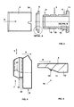
- the connector 1 shown in Figures 1-3 comprises a spigot 3, a sleeve 4 and a coupling part 5 for holding the sleeve 4 onto the spigot 3.
- the spigot 3 is of substantially tubular shape and typically made of plastic or metal. It has a first end 6 that may for instance be connected to a fitting body (not shown) and a free, second end 8 that in use is inserted into a pipe end (not shown). To facilitate such insertion, the second end 8 may for instance be rounded, chamfered or be provided with some other friction reducing profile.
- the spigot 3 is near its first end 6 provided with a seat 10, designed to cooperate with the coupling part 5.
- This seat 10, in the illustrated embodiment shown in Figure 5 comprises a cylindrical portion 12 of increased outer diameter and a conical transition portion 13 which ends in first retention means 14.
- These first retention means 14 are arranged to cooperate with first engaging means 21 of the coupling part 5, so as to allow said coupling part 5 to be mounted onto the seat 10 (in the assembly direction indicated by arrow A) and prevent removal of the coupling part 5 in the opposite direction.
- the first retention means 14 may for instance comprise one or more barb shaped projections or a circumferential ridge, as shown. Other embodiments are possible, depending on the design of the first engaging means 21.
- the seat 10 may at its other end be provided with stopper means 11, to limit movement of the coupling part 5 in the assembly direction A.
- These stopper means 11 may for instance comprise a stepped shoulder, a circumferential flange and/or several projections or notches.
- the spigot 3 may further be provided with one or more circumferential grooves 15 for holding sealing means (not shown), such as for instance an 0-ring.
- the spigot 3 may be provided with gripping means 16 for resisting removal of the spigot 3 from a pipe end in which it has been inserted.
- gripping means 16 may for instance comprise one or more tooth shaped ridges extending along at least part of the spigot's outer circumference.
- the sleeve 4 is of substantially cylindrical design and is typically made of metal.
- the sleeve 4 is dimensioned to surround the spigot 3 at some radial distance so as to enclose a ring shaped gap 18, suitable for receiving a pipe end (not shown).
- the sleeve 4 is near one or both of its ends provided with second retention means 24, arranged for cooperation with second engaging means 22 of the coupling part 5.
- the second retention means 24 may for instance be formed by bending the sleeve's edge or part(s) thereof, inward (as shown) and/or outward.
- the sleeve 4 may be provided with notches, indentations or the like profiles.
- the coupling part 5 is of substantially annular shape and typically made of a slightly resilient material, such as for instance plastic.
- the coupling part 5 comprises first engaging means 21 for engaging the spigot 3 and second engaging means 22 for engaging the press sleeve 4.
- the first engaging means 21 can be located at an inner side of the coupling part 5. They may for instance comprise one or more barb shaped projections or a barb shaped ridge extending along at least part of the coupling part's inner circumference.
- the first engaging means 21 are shaped such that the inner contour of the coupling part 5 substantially matches the outer contour of the seat 10, as will be appreciated by comparing Figures 4 and 5 .
- the second engaging means 22 can be located at an outer side of the coupling part 5 and may likewise be shaped as barb shaped projections or a ridge extending along at least part of the coupling part's outer circumference.
- the first and second engaging means 21, 22 are located at a first end portion 7 of the coupling part 5, where the coupling part 5 has a relatively small wall thickness and consequently, certain flexibility in radial direction.
- the first engaging means 21 are located slightly closer to the free edge of said end portion 7 than the second engaging means 22, or in other words, when seen in the assembly direction A of the coupling part 5, the first engaging means 21 are located upstream of the second engaging means 22.
- the other end portion of the coupling part 5 may be provided with a circumferential flange 9, having an outer diameter that preferably at least matches that of the sleeve 4. As best seen in Figure 4, a groove 23 is formed between said flange 9 and the second engaging means 22.
- the connector 1 can be assembled as follows. First, the coupling part 5 is with its first end portion 7 inserted into the sleeve 4, until the second engaging means 22 snap behind the second retention means 24, thereby engaging the sleeve 4 at a second engaging position II (as indicated in Figure 3 ). The second retention means 24 are thus retained in the groove 23. The second engaging means 22 are thus arranged to retain the sleeve 4 onto the coupling part 5, before the coupling part 5 and/or the sleeve 4 is mounted onto the spigot 3.
- first engaging position I is located upstream of the second engaging position II, as seen in the assembly direction A of the sleeve 4.
- the coupling part 5 may be progressed along the seat 10 till the flange 9 abuts the stopper means 11.
- the flange 9 may function as separation wall, preventing direct contact between the spigot 3 on the one hand and the sleeve 4 and/or an inserted pipe end at the other hand. This is in particular advantageous when the spigot 3 is made of metal.
Landscapes
- Engineering & Computer Science (AREA)
- General Engineering & Computer Science (AREA)
- Mechanical Engineering (AREA)
- Quick-Acting Or Multi-Walled Pipe Joints (AREA)
- Multi-Conductor Connections (AREA)
- Mechanical Coupling Of Light Guides (AREA)
- Coupling Device And Connection With Printed Circuit (AREA)
Priority Applications (1)
| Application Number | Priority Date | Filing Date | Title |
|---|---|---|---|
| PL09005929T PL2113706T3 (pl) | 2008-04-29 | 2009-04-29 | Złączka wciskana z ulepszoną częścią łączącą do trzymania tulei wciskanej |
Applications Claiming Priority (1)
| Application Number | Priority Date | Filing Date | Title |
|---|---|---|---|
| NL1035370A NL1035370C2 (nl) | 2008-04-29 | 2008-04-29 | Perskoppeling met verbeterd koppeldeel voor het vasthouden van een pershuls. |
Publications (2)
| Publication Number | Publication Date |
|---|---|
| EP2113706A1 true EP2113706A1 (fr) | 2009-11-04 |
| EP2113706B1 EP2113706B1 (fr) | 2012-07-04 |
Family
ID=39869192
Family Applications (1)
| Application Number | Title | Priority Date | Filing Date |
|---|---|---|---|
| EP09005929A Not-in-force EP2113706B1 (fr) | 2008-04-29 | 2009-04-29 | Connecteur d'insertion avec pièce de couplage amélioré pour maintenir un manchon de presse |
Country Status (7)
| Country | Link |
|---|---|
| EP (1) | EP2113706B1 (fr) |
| DE (1) | DE202008007137U1 (fr) |
| DK (1) | DK2113706T3 (fr) |
| ES (1) | ES2390210T3 (fr) |
| HR (1) | HRP20120757T1 (fr) |
| NL (1) | NL1035370C2 (fr) |
| PL (1) | PL2113706T3 (fr) |
Families Citing this family (4)
| Publication number | Priority date | Publication date | Assignee | Title |
|---|---|---|---|---|
| CN102803646B (zh) | 2009-12-15 | 2016-04-20 | 菲伯斯公司 | 用于从地下井去除流体的系统和方法 |
| DE202011107346U1 (de) * | 2011-06-06 | 2012-09-07 | Wavin B.V. | Anschlussfitting |
| WO2014026190A1 (fr) * | 2012-08-10 | 2014-02-13 | National Oilwell Varco, L.P. | Raccords de tubulure enroulés composites |
| EP3021026B1 (fr) * | 2014-11-12 | 2018-07-11 | Pipelife Nederland B.V. | Construction de couplage de tuyau haute pression |
Citations (7)
| Publication number | Priority date | Publication date | Assignee | Title |
|---|---|---|---|---|
| GB561283A (en) * | 1942-11-26 | 1944-05-12 | Automotive Prod Co Ltd | Improvements in or relating to end fittings for flexible hoses |
| US2410600A (en) * | 1943-08-12 | 1946-11-05 | Cowles Irving | Flexible conduit and coupling for same |
| EP0067063A1 (fr) * | 1981-06-10 | 1982-12-15 | Unilever Plc | Raccord pour extrémité de tuyau souple |
| EP0611911A1 (fr) | 1993-02-16 | 1994-08-24 | FRÄNKISCHE ROHRWERKE, GEBR. KIRCHNER GmbH & Co. | Raccord étanche des tuyaux composites en matière plastique-métal-plastique |
| DE19735919C1 (de) * | 1997-08-19 | 1998-11-26 | Hewing Gmbh | Anschlußvorrichtung für ein Rohr, insbesondere ein Kunststoffrohr oder ein Kunststoff-Metall-Verbundrohr |
| DE29901935U1 (de) * | 1998-04-17 | 1999-04-15 | Jäggi, Georg, Kaumberg | Leitungssystem |
| EP1126206A1 (fr) * | 2000-02-17 | 2001-08-22 | Roth Werke GmbH | Raccord de compression pour tuyaux |
-
2008
- 2008-04-29 NL NL1035370A patent/NL1035370C2/nl not_active IP Right Cessation
- 2008-05-28 DE DE202008007137U patent/DE202008007137U1/de not_active Expired - Lifetime
-
2009
- 2009-04-29 ES ES09005929T patent/ES2390210T3/es active Active
- 2009-04-29 EP EP09005929A patent/EP2113706B1/fr not_active Not-in-force
- 2009-04-29 DK DK09005929.6T patent/DK2113706T3/da active
- 2009-04-29 PL PL09005929T patent/PL2113706T3/pl unknown
-
2012
- 2012-09-25 HR HRP20120757AT patent/HRP20120757T1/hr unknown
Patent Citations (7)
| Publication number | Priority date | Publication date | Assignee | Title |
|---|---|---|---|---|
| GB561283A (en) * | 1942-11-26 | 1944-05-12 | Automotive Prod Co Ltd | Improvements in or relating to end fittings for flexible hoses |
| US2410600A (en) * | 1943-08-12 | 1946-11-05 | Cowles Irving | Flexible conduit and coupling for same |
| EP0067063A1 (fr) * | 1981-06-10 | 1982-12-15 | Unilever Plc | Raccord pour extrémité de tuyau souple |
| EP0611911A1 (fr) | 1993-02-16 | 1994-08-24 | FRÄNKISCHE ROHRWERKE, GEBR. KIRCHNER GmbH & Co. | Raccord étanche des tuyaux composites en matière plastique-métal-plastique |
| DE19735919C1 (de) * | 1997-08-19 | 1998-11-26 | Hewing Gmbh | Anschlußvorrichtung für ein Rohr, insbesondere ein Kunststoffrohr oder ein Kunststoff-Metall-Verbundrohr |
| DE29901935U1 (de) * | 1998-04-17 | 1999-04-15 | Jäggi, Georg, Kaumberg | Leitungssystem |
| EP1126206A1 (fr) * | 2000-02-17 | 2001-08-22 | Roth Werke GmbH | Raccord de compression pour tuyaux |
Also Published As
| Publication number | Publication date |
|---|---|
| ES2390210T3 (es) | 2012-11-07 |
| DK2113706T3 (da) | 2012-08-27 |
| NL1035370C2 (nl) | 2009-10-30 |
| DE202008007137U1 (de) | 2008-10-16 |
| HRP20120757T1 (hr) | 2012-10-31 |
| PL2113706T3 (pl) | 2012-11-30 |
| EP2113706B1 (fr) | 2012-07-04 |
Similar Documents
| Publication | Publication Date | Title |
|---|---|---|
| EP1933074B1 (fr) | Améliorations portant sur ou en relation avec le couplage de tube | |
| US6179347B1 (en) | Snap-action pipe coupling retainer with a rhomboidal cross-section | |
| US9447906B2 (en) | Self-locking push-to-connect insert | |
| US6173999B1 (en) | Tube coupling devices | |
| EP2282101B1 (fr) | Système de raccord de tuyau avec un raccord mâle encliquetable | |
| EP2140191B1 (fr) | Raccord de tuyaux | |
| KR101670111B1 (ko) | 지지 슬리브를 구비한 푸쉬-피트 파이프 피팅 시스템 | |
| US4932689A (en) | Hose fitting assembly | |
| WO2005114031A2 (fr) | Raccord de canalisation | |
| EP2113706B1 (fr) | Connecteur d'insertion avec pièce de couplage amélioré pour maintenir un manchon de presse | |
| CN107407446A (zh) | 压装套筒、压装接头以及压装接头或压装套筒的应用 | |
| US20100045032A1 (en) | Tube Coupling Device | |
| EP2906840B1 (fr) | Terminal pour ensemble de transmission de mouvement commandé à distance | |
| US6527575B2 (en) | Electrical plug connector half | |
| EP4042053B1 (fr) | Raccord rapide | |
| EP3523564B1 (fr) | Raccord d'extrémité de tuyau et procédé correspondant | |
| US10876656B2 (en) | Hose clamp | |
| US12338929B2 (en) | Push fitting for metallic pipe | |
| CN115715356B (zh) | 密封锁定组件 | |
| KR102120723B1 (ko) | 차량용 이종 재질 호스 연결소켓 조립구조 | |
| CN113565903B (zh) | 一种轮边制动器销轴防拉脱结构 | |
| US20100044177A1 (en) | Free-wheel comprising a band element | |
| WO2003012329A1 (fr) | Element rapporte pour raccord hydraulique et raccord hydraulique comprenant un tel element rapporte | |
| AU644582B2 (en) | Improvements in or relating to connectors | |
| EP1004808A1 (fr) | Raccord rapide pour tuyaux flexibles |
Legal Events
| Date | Code | Title | Description |
|---|---|---|---|
| PUAI | Public reference made under article 153(3) epc to a published international application that has entered the european phase |
Free format text: ORIGINAL CODE: 0009012 |
|
| AK | Designated contracting states |
Kind code of ref document: A1 Designated state(s): AT BE BG CH CY CZ DE DK EE ES FI FR GB GR HR HU IE IS IT LI LT LU LV MC MK MT NL NO PL PT RO SE SI SK TR |
|
| 17P | Request for examination filed |
Effective date: 20091112 |
|
| 17Q | First examination report despatched |
Effective date: 20091208 |
|
| GRAP | Despatch of communication of intention to grant a patent |
Free format text: ORIGINAL CODE: EPIDOSNIGR1 |
|
| GRAS | Grant fee paid |
Free format text: ORIGINAL CODE: EPIDOSNIGR3 |
|
| GRAA | (expected) grant |
Free format text: ORIGINAL CODE: 0009210 |
|
| AK | Designated contracting states |
Kind code of ref document: B1 Designated state(s): AT BE BG CH CY CZ DE DK EE ES FI FR GB GR HR HU IE IS IT LI LT LU LV MC MK MT NL NO PL PT RO SE SI SK TR |
|
| REG | Reference to a national code |
Ref country code: GB Ref legal event code: FG4D |
|
| REG | Reference to a national code |
Ref country code: CH Ref legal event code: EP |
|
| REG | Reference to a national code |
Ref country code: AT Ref legal event code: REF Ref document number: 565313 Country of ref document: AT Kind code of ref document: T Effective date: 20120715 |
|
| REG | Reference to a national code |
Ref country code: IE Ref legal event code: FG4D |
|
| REG | Reference to a national code |
Ref country code: DK Ref legal event code: T3 |
|
| REG | Reference to a national code |
Ref country code: DE Ref legal event code: R096 Ref document number: 602009007953 Country of ref document: DE Effective date: 20120830 |
|
| REG | Reference to a national code |
Ref country code: HR Ref legal event code: TUEP Ref document number: P20120757 Country of ref document: HR |
|
| REG | Reference to a national code |
Ref country code: EE Ref legal event code: FG4A Ref document number: E007008 Country of ref document: EE Effective date: 20120801 |
|
| REG | Reference to a national code |
Ref country code: NL Ref legal event code: T3 |
|
| REG | Reference to a national code |
Ref country code: HR Ref legal event code: T1PR Ref document number: P20120757 Country of ref document: HR |
|
| REG | Reference to a national code |
Ref country code: ES Ref legal event code: FG2A Ref document number: 2390210 Country of ref document: ES Kind code of ref document: T3 Effective date: 20121107 |
|
| PG25 | Lapsed in a contracting state [announced via postgrant information from national office to epo] |
Ref country code: SI Free format text: LAPSE BECAUSE OF FAILURE TO SUBMIT A TRANSLATION OF THE DESCRIPTION OR TO PAY THE FEE WITHIN THE PRESCRIBED TIME-LIMIT Effective date: 20120704 |
|
| REG | Reference to a national code |
Ref country code: PL Ref legal event code: T3 |
|
| REG | Reference to a national code |
Ref country code: SK Ref legal event code: T3 Ref document number: E 12518 Country of ref document: SK |
|
| PG25 | Lapsed in a contracting state [announced via postgrant information from national office to epo] |
Ref country code: NO Free format text: LAPSE BECAUSE OF FAILURE TO SUBMIT A TRANSLATION OF THE DESCRIPTION OR TO PAY THE FEE WITHIN THE PRESCRIBED TIME-LIMIT Effective date: 20121004 Ref country code: CY Free format text: LAPSE BECAUSE OF FAILURE TO SUBMIT A TRANSLATION OF THE DESCRIPTION OR TO PAY THE FEE WITHIN THE PRESCRIBED TIME-LIMIT Effective date: 20120704 Ref country code: FI Free format text: LAPSE BECAUSE OF FAILURE TO SUBMIT A TRANSLATION OF THE DESCRIPTION OR TO PAY THE FEE WITHIN THE PRESCRIBED TIME-LIMIT Effective date: 20120704 Ref country code: IS Free format text: LAPSE BECAUSE OF FAILURE TO SUBMIT A TRANSLATION OF THE DESCRIPTION OR TO PAY THE FEE WITHIN THE PRESCRIBED TIME-LIMIT Effective date: 20121104 |
|
| PG25 | Lapsed in a contracting state [announced via postgrant information from national office to epo] |
Ref country code: GR Free format text: LAPSE BECAUSE OF FAILURE TO SUBMIT A TRANSLATION OF THE DESCRIPTION OR TO PAY THE FEE WITHIN THE PRESCRIBED TIME-LIMIT Effective date: 20121005 Ref country code: LV Free format text: LAPSE BECAUSE OF FAILURE TO SUBMIT A TRANSLATION OF THE DESCRIPTION OR TO PAY THE FEE WITHIN THE PRESCRIBED TIME-LIMIT Effective date: 20120704 Ref country code: PT Free format text: LAPSE BECAUSE OF FAILURE TO SUBMIT A TRANSLATION OF THE DESCRIPTION OR TO PAY THE FEE WITHIN THE PRESCRIBED TIME-LIMIT Effective date: 20121105 Ref country code: SE Free format text: LAPSE BECAUSE OF FAILURE TO SUBMIT A TRANSLATION OF THE DESCRIPTION OR TO PAY THE FEE WITHIN THE PRESCRIBED TIME-LIMIT Effective date: 20120704 |
|
| PG25 | Lapsed in a contracting state [announced via postgrant information from national office to epo] |
Ref country code: RO Free format text: LAPSE BECAUSE OF FAILURE TO SUBMIT A TRANSLATION OF THE DESCRIPTION OR TO PAY THE FEE WITHIN THE PRESCRIBED TIME-LIMIT Effective date: 20120704 |
|
| PLBE | No opposition filed within time limit |
Free format text: ORIGINAL CODE: 0009261 |
|
| STAA | Information on the status of an ep patent application or granted ep patent |
Free format text: STATUS: NO OPPOSITION FILED WITHIN TIME LIMIT |
|
| 26N | No opposition filed |
Effective date: 20130405 |
|
| REG | Reference to a national code |
Ref country code: HU Ref legal event code: AG4A Ref document number: E015355 Country of ref document: HU |
|
| PG25 | Lapsed in a contracting state [announced via postgrant information from national office to epo] |
Ref country code: BG Free format text: LAPSE BECAUSE OF FAILURE TO SUBMIT A TRANSLATION OF THE DESCRIPTION OR TO PAY THE FEE WITHIN THE PRESCRIBED TIME-LIMIT Effective date: 20121004 |
|
| REG | Reference to a national code |
Ref country code: DE Ref legal event code: R097 Ref document number: 602009007953 Country of ref document: DE Effective date: 20130405 |
|
| REG | Reference to a national code |
Ref country code: HR Ref legal event code: PBON Ref document number: P20120757 Country of ref document: HR Effective date: 20130430 |
|
| PG25 | Lapsed in a contracting state [announced via postgrant information from national office to epo] |
Ref country code: MC Free format text: LAPSE BECAUSE OF FAILURE TO SUBMIT A TRANSLATION OF THE DESCRIPTION OR TO PAY THE FEE WITHIN THE PRESCRIBED TIME-LIMIT Effective date: 20120704 |
|
| REG | Reference to a national code |
Ref country code: CH Ref legal event code: PL |
|
| REG | Reference to a national code |
Ref country code: DK Ref legal event code: EBP Effective date: 20130430 |
|
| REG | Reference to a national code |
Ref country code: EE Ref legal event code: MM4A Ref document number: E007008 Country of ref document: EE Effective date: 20130430 |
|
| REG | Reference to a national code |
Ref country code: LT Ref legal event code: MM4D Effective date: 20130429 |
|
| REG | Reference to a national code |
Ref country code: SK Ref legal event code: MM4A Ref document number: E 12518 Country of ref document: SK Effective date: 20130429 |
|
| REG | Reference to a national code |
Ref country code: IE Ref legal event code: MM4A |
|
| PG25 | Lapsed in a contracting state [announced via postgrant information from national office to epo] |
Ref country code: SK Free format text: LAPSE BECAUSE OF NON-PAYMENT OF DUE FEES Effective date: 20130429 Ref country code: EE Free format text: LAPSE BECAUSE OF NON-PAYMENT OF DUE FEES Effective date: 20130430 Ref country code: HR Free format text: LAPSE BECAUSE OF NON-PAYMENT OF DUE FEES Effective date: 20130430 Ref country code: LT Free format text: LAPSE BECAUSE OF NON-PAYMENT OF DUE FEES Effective date: 20130429 Ref country code: CH Free format text: LAPSE BECAUSE OF NON-PAYMENT OF DUE FEES Effective date: 20130430 Ref country code: LI Free format text: LAPSE BECAUSE OF NON-PAYMENT OF DUE FEES Effective date: 20130430 |
|
| PG25 | Lapsed in a contracting state [announced via postgrant information from national office to epo] |
Ref country code: HU Free format text: LAPSE BECAUSE OF NON-PAYMENT OF DUE FEES Effective date: 20130430 |
|
| PG25 | Lapsed in a contracting state [announced via postgrant information from national office to epo] |
Ref country code: DK Free format text: LAPSE BECAUSE OF NON-PAYMENT OF DUE FEES Effective date: 20130430 Ref country code: IE Free format text: LAPSE BECAUSE OF NON-PAYMENT OF DUE FEES Effective date: 20130429 |
|
| PG25 | Lapsed in a contracting state [announced via postgrant information from national office to epo] |
Ref country code: MT Free format text: LAPSE BECAUSE OF FAILURE TO SUBMIT A TRANSLATION OF THE DESCRIPTION OR TO PAY THE FEE WITHIN THE PRESCRIBED TIME-LIMIT Effective date: 20120704 |
|
| PG25 | Lapsed in a contracting state [announced via postgrant information from national office to epo] |
Ref country code: TR Free format text: LAPSE BECAUSE OF FAILURE TO SUBMIT A TRANSLATION OF THE DESCRIPTION OR TO PAY THE FEE WITHIN THE PRESCRIBED TIME-LIMIT Effective date: 20120704 |
|
| PG25 | Lapsed in a contracting state [announced via postgrant information from national office to epo] |
Ref country code: MK Free format text: LAPSE BECAUSE OF FAILURE TO SUBMIT A TRANSLATION OF THE DESCRIPTION OR TO PAY THE FEE WITHIN THE PRESCRIBED TIME-LIMIT Effective date: 20120704 Ref country code: LU Free format text: LAPSE BECAUSE OF NON-PAYMENT OF DUE FEES Effective date: 20130429 |
|
| REG | Reference to a national code |
Ref country code: FR Ref legal event code: PLFP Year of fee payment: 8 |
|
| REG | Reference to a national code |
Ref country code: FR Ref legal event code: PLFP Year of fee payment: 9 |
|
| REG | Reference to a national code |
Ref country code: FR Ref legal event code: PLFP Year of fee payment: 10 |
|
| REG | Reference to a national code |
Ref country code: FR Ref legal event code: PLFP Year of fee payment: 15 |
|
| PGFP | Annual fee paid to national office [announced via postgrant information from national office to epo] |
Ref country code: NL Payment date: 20230412 Year of fee payment: 15 |
|
| PGFP | Annual fee paid to national office [announced via postgrant information from national office to epo] |
Ref country code: IT Payment date: 20230414 Year of fee payment: 15 Ref country code: FR Payment date: 20230412 Year of fee payment: 15 Ref country code: ES Payment date: 20230505 Year of fee payment: 15 Ref country code: DE Payment date: 20230414 Year of fee payment: 15 Ref country code: CZ Payment date: 20230425 Year of fee payment: 15 |
|
| PGFP | Annual fee paid to national office [announced via postgrant information from national office to epo] |
Ref country code: PL Payment date: 20230421 Year of fee payment: 15 Ref country code: AT Payment date: 20230425 Year of fee payment: 15 |
|
| PGFP | Annual fee paid to national office [announced via postgrant information from national office to epo] |
Ref country code: BE Payment date: 20230412 Year of fee payment: 15 |
|
| PGFP | Annual fee paid to national office [announced via postgrant information from national office to epo] |
Ref country code: GB Payment date: 20230413 Year of fee payment: 15 |
|
| REG | Reference to a national code |
Ref country code: DE Ref legal event code: R119 Ref document number: 602009007953 Country of ref document: DE |
|
| REG | Reference to a national code |
Ref country code: NL Ref legal event code: MM Effective date: 20240501 |
|
| REG | Reference to a national code |
Ref country code: AT Ref legal event code: MM01 Ref document number: 565313 Country of ref document: AT Kind code of ref document: T Effective date: 20240429 |
|
| GBPC | Gb: european patent ceased through non-payment of renewal fee |
Effective date: 20240429 |
|
| REG | Reference to a national code |
Ref country code: BE Ref legal event code: MM Effective date: 20240430 |
|
| PG25 | Lapsed in a contracting state [announced via postgrant information from national office to epo] |
Ref country code: DE Free format text: LAPSE BECAUSE OF NON-PAYMENT OF DUE FEES Effective date: 20241105 |
|
| PG25 | Lapsed in a contracting state [announced via postgrant information from national office to epo] |
Ref country code: NL Free format text: LAPSE BECAUSE OF NON-PAYMENT OF DUE FEES Effective date: 20240501 Ref country code: BE Free format text: LAPSE BECAUSE OF NON-PAYMENT OF DUE FEES Effective date: 20240430 |
|
| PG25 | Lapsed in a contracting state [announced via postgrant information from national office to epo] |
Ref country code: GB Free format text: LAPSE BECAUSE OF NON-PAYMENT OF DUE FEES Effective date: 20240429 |
|
| PG25 | Lapsed in a contracting state [announced via postgrant information from national office to epo] |
Ref country code: FR Free format text: LAPSE BECAUSE OF NON-PAYMENT OF DUE FEES Effective date: 20240430 |
|
| PG25 | Lapsed in a contracting state [announced via postgrant information from national office to epo] |
Ref country code: AT Free format text: LAPSE BECAUSE OF NON-PAYMENT OF DUE FEES Effective date: 20240429 |
|
| PG25 | Lapsed in a contracting state [announced via postgrant information from national office to epo] |
Ref country code: CZ Free format text: LAPSE BECAUSE OF NON-PAYMENT OF DUE FEES Effective date: 20240429 |
|
| PG25 | Lapsed in a contracting state [announced via postgrant information from national office to epo] |
Ref country code: NL Free format text: LAPSE BECAUSE OF NON-PAYMENT OF DUE FEES Effective date: 20240501 Ref country code: GB Free format text: LAPSE BECAUSE OF NON-PAYMENT OF DUE FEES Effective date: 20240429 Ref country code: FR Free format text: LAPSE BECAUSE OF NON-PAYMENT OF DUE FEES Effective date: 20240430 Ref country code: DE Free format text: LAPSE BECAUSE OF NON-PAYMENT OF DUE FEES Effective date: 20241105 Ref country code: CZ Free format text: LAPSE BECAUSE OF NON-PAYMENT OF DUE FEES Effective date: 20240429 Ref country code: BE Free format text: LAPSE BECAUSE OF NON-PAYMENT OF DUE FEES Effective date: 20240430 Ref country code: AT Free format text: LAPSE BECAUSE OF NON-PAYMENT OF DUE FEES Effective date: 20240429 |
|
| PG25 | Lapsed in a contracting state [announced via postgrant information from national office to epo] |
Ref country code: PL Free format text: LAPSE BECAUSE OF NON-PAYMENT OF DUE FEES Effective date: 20240429 |
|
| PG25 | Lapsed in a contracting state [announced via postgrant information from national office to epo] |
Ref country code: IT Free format text: LAPSE BECAUSE OF NON-PAYMENT OF DUE FEES Effective date: 20240429 |
|
| REG | Reference to a national code |
Ref country code: ES Ref legal event code: FD2A Effective date: 20250604 |
|
| PG25 | Lapsed in a contracting state [announced via postgrant information from national office to epo] |
Ref country code: ES Free format text: LAPSE BECAUSE OF NON-PAYMENT OF DUE FEES Effective date: 20240430 |