EP2113722A2 - Kontrollsystem für die Ausgabetemperatur für gegen das Legionellenbakterium desinfiziertes Warmwasser zur sanitären Verwendung mit zentralisierter Produktion bei hohen Termpaturen - Google Patents
Kontrollsystem für die Ausgabetemperatur für gegen das Legionellenbakterium desinfiziertes Warmwasser zur sanitären Verwendung mit zentralisierter Produktion bei hohen Termpaturen Download PDFInfo
- Publication number
- EP2113722A2 EP2113722A2 EP09425150A EP09425150A EP2113722A2 EP 2113722 A2 EP2113722 A2 EP 2113722A2 EP 09425150 A EP09425150 A EP 09425150A EP 09425150 A EP09425150 A EP 09425150A EP 2113722 A2 EP2113722 A2 EP 2113722A2
- Authority
- EP
- European Patent Office
- Prior art keywords
- temperature
- celsius
- waters
- water
- distribution
- Prior art date
- Legal status (The legal status is an assumption and is not a legal conclusion. Google has not performed a legal analysis and makes no representation as to the accuracy of the status listed.)
- Withdrawn
Links
Images
Classifications
-
- F—MECHANICAL ENGINEERING; LIGHTING; HEATING; WEAPONS; BLASTING
- F24—HEATING; RANGES; VENTILATING
- F24D—DOMESTIC- OR SPACE-HEATING SYSTEMS, e.g. CENTRAL HEATING SYSTEMS; DOMESTIC HOT-WATER SUPPLY SYSTEMS; ELEMENTS OR COMPONENTS THEREFOR
- F24D17/00—Domestic hot-water supply systems
- F24D17/0078—Recirculation systems
-
- F—MECHANICAL ENGINEERING; LIGHTING; HEATING; WEAPONS; BLASTING
- F24—HEATING; RANGES; VENTILATING
- F24D—DOMESTIC- OR SPACE-HEATING SYSTEMS, e.g. CENTRAL HEATING SYSTEMS; DOMESTIC HOT-WATER SUPPLY SYSTEMS; ELEMENTS OR COMPONENTS THEREFOR
- F24D17/00—Domestic hot-water supply systems
- F24D17/0073—Arrangements for preventing the occurrence or proliferation of microorganisms in the water
-
- F—MECHANICAL ENGINEERING; LIGHTING; HEATING; WEAPONS; BLASTING
- F24—HEATING; RANGES; VENTILATING
- F24D—DOMESTIC- OR SPACE-HEATING SYSTEMS, e.g. CENTRAL HEATING SYSTEMS; DOMESTIC HOT-WATER SUPPLY SYSTEMS; ELEMENTS OR COMPONENTS THEREFOR
- F24D19/00—Details
- F24D19/10—Arrangement or mounting of control or safety devices
- F24D19/1006—Arrangement or mounting of control or safety devices for water heating systems
- F24D19/1051—Arrangement or mounting of control or safety devices for water heating systems for domestic hot water
Definitions
- the Legionella bacterium may be found in all cold water fed hydraulic systems and may remain present in a state of relative quiescence up until the host temperature is inferior to 24° Celsius.
- the innovation introduced by the system subject of this invention in the field of the processes involved in the production and distribution of hot water for sanitary uses, is represented by the possibility that it offers to avoid any introduction of the Legionella bacterium through physical mixing between hot disinfected waters (disinfected at 70° Celsius by the boiler and then stocked in its reservoir) and potentially infected cold water coming from the main water supply feed, by means of a heat exchanger which consists of two parallel internal hydraulic circuits that avoid such physical contact while providing an adequate cooling in order to reach the ideal distribution temperature of 48-50 ° Celsius.
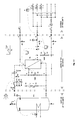
- Fig. 1/1 the cold water fed by the main water supply, arriving from the primary incoming water connection Fig. 1/1(A) , goes through the primary circuit Fig. 1/1(C-D) of the plate based heat exchanger Fig. 1/1(SC) is pre-heated and then, afterwards, is sent to the primary output of the system Fig. 1/1(F) and, from here, directly to the boiler with reservoir Fig. 1/1(T) (outside of the limits of the present invention) where it is heated and definitively disinfected at a temperature equal to or higher than 70°Celsius.
- the water recirculation system Fig. 1/1(S) (outside the limits of the present invention), through the secondary system feed Fig. 1/1(N) and the primary output Fig. 1/1(F) feeds its whole flow (Already 100% disinfected) to the boiler Fig. 1/1(T) without any mixing in case of no demand from the attached utilities, or , with a partial mix taking place at point Fig. 1/1(E) with the water fed by the primary output of the plate based heat exchanger Fig. 1/1(SC) , if the demand from the utilities is present. After this action takes place, it is newly fed to the boiler which provides a new cycle of disinfection at a temperature equal or greater than 70° Celsius.
- a regulation present within the limits of the invention which consists, essentially, in a motorized two-way modulating hydraulic valve Fig. 1/1(VMA) which derives water from the main cold water supply and bypasses Fig. 1/1(B-E) on the primary stage of the plate based heat exchanger Fig. 1/1(SC) (which functions as a cooler) that modulates the total flow of residual waters from the main cold water supply in the heat exchanger itself and thus its cooling capacity according to the setting of the regulator Fig. 1/1(REG) and the data provided by the submerged sensor probe Fig. 1/1(SI) in order to maintain the temperature of the hot water for sanitary uses to be sent to the utilities Fig.
- VMA motorized two-way modulating hydraulic valve
- Fig. 1/1(SC) which functions as a cooler
- Fig. 1/1(VMR) there is also a two-way, servo-assisted flow modulating valve Fig. 1/1(VMR) , on the output and deriving the secondary feed of the water recirculation system Fig. 1/1(N) , which , depending on the rate of flow drawn from Fig. 1/1(M) deviates Fig. 1/1(O-L) partially or totally towards the recirculation system, thus avoiding to feed its total flow back towards the boiler's reservoir, which holds the water at a temperature of 70°C or above, and from here, by means of the secondary stage Fig.
- Such two-way valve Fig. 1/1(VMR) with an adequate programmable timer-driven stop mechanism, activated by a signal outside of the limits of the present invention, can also be used to cancel (once its closing has been forced) the deviation of the water recirculation system's flow towards the distribution Fig. 1/1(O-L) for a time which corresponds to the programmed lack of demand, sending it, instead, all back to the boiler's reservoir (which maintains the water at a temperature of 70° Celsius and above) and to the secondary feed of the Fig.
- the normally closed solenoid valve Fig. 1/1(VS) commanded by the security thermostat Fig. 1/1(TS) , is inserted immediately after the secondary incoming water feed Fig. 1/1(G) in order to intercept the water fed to the utilities from the boiler's reservoir, in case its temperature falls below the programmed temperature (70° Celsius and above).
- the second alarm triggering thermostat Fig. 1/1(TA) (always installed) which controls the disinfection temperature (70° Celsius and above) of the incoming feed of the system and which eventually, in case of an anomaly, sends the alarm signal to the control room.
- the electrical panel Fig. 1/1(QE) which feeds and controls all devices within the present invention
- the boiler Fig. 1/1 (T) heating system Fig. 1/1(U) , its temperature regulation system Fig. 1/1(V) and Fig. 1/1(Z) (which may be of any type, with any means of regulation and any method of heating which present day technology consents e.g. direct flame, electricity, fluid exchange induced by heating waters, superheated waters, steam etc.) the water re-circulating unit Fig. 1/1(S) and the burn prevention system Fig. 1/1(R), Fig. 1/1(P), and Fig. 1/1(Q) .
Landscapes
- Engineering & Computer Science (AREA)
- Physics & Mathematics (AREA)
- Thermal Sciences (AREA)
- Chemical & Material Sciences (AREA)
- Combustion & Propulsion (AREA)
- Mechanical Engineering (AREA)
- General Engineering & Computer Science (AREA)
- Apparatus For Disinfection Or Sterilisation (AREA)
- Bidet-Like Cleaning Device And Other Flush Toilet Accessories (AREA)
- Heat Treatment Of Water, Waste Water Or Sewage (AREA)
Applications Claiming Priority (1)
| Application Number | Priority Date | Filing Date | Title |
|---|---|---|---|
| IT000028A ITNA20080028A1 (it) | 2008-05-02 | 2008-05-02 | Sistema di controllo della temperatura di distribuzione dell'acqua calda sanitaria disinfettata dalla legionella con produzione centralizzata. |
Publications (1)
| Publication Number | Publication Date |
|---|---|
| EP2113722A2 true EP2113722A2 (de) | 2009-11-04 |
Family
ID=40302895
Family Applications (1)
| Application Number | Title | Priority Date | Filing Date |
|---|---|---|---|
| EP09425150A Withdrawn EP2113722A2 (de) | 2008-05-02 | 2009-04-22 | Kontrollsystem für die Ausgabetemperatur für gegen das Legionellenbakterium desinfiziertes Warmwasser zur sanitären Verwendung mit zentralisierter Produktion bei hohen Termpaturen |
Country Status (2)
| Country | Link |
|---|---|
| EP (1) | EP2113722A2 (de) |
| IT (1) | ITNA20080028A1 (de) |
Cited By (3)
| Publication number | Priority date | Publication date | Assignee | Title |
|---|---|---|---|---|
| CN103512397A (zh) * | 2013-09-29 | 2014-01-15 | 无锡荣能半导体材料有限公司 | 一种自动控温的板式换热器 |
| EP2876376A3 (de) * | 2013-09-07 | 2015-09-02 | Gerd Haberland | Anordnung und Warmwasserzirkulationstrenner für ein Warmwasserversorgungssystem |
| ES2633130R1 (es) * | 2016-03-16 | 2017-10-31 | Riello S.P.A. | Calentador de agua |
-
2008
- 2008-05-02 IT IT000028A patent/ITNA20080028A1/it unknown
-
2009
- 2009-04-22 EP EP09425150A patent/EP2113722A2/de not_active Withdrawn
Cited By (4)
| Publication number | Priority date | Publication date | Assignee | Title |
|---|---|---|---|---|
| EP2876376A3 (de) * | 2013-09-07 | 2015-09-02 | Gerd Haberland | Anordnung und Warmwasserzirkulationstrenner für ein Warmwasserversorgungssystem |
| CN103512397A (zh) * | 2013-09-29 | 2014-01-15 | 无锡荣能半导体材料有限公司 | 一种自动控温的板式换热器 |
| CN103512397B (zh) * | 2013-09-29 | 2015-07-15 | 无锡荣能半导体材料有限公司 | 一种自动控温的板式换热器 |
| ES2633130R1 (es) * | 2016-03-16 | 2017-10-31 | Riello S.P.A. | Calentador de agua |
Also Published As
| Publication number | Publication date |
|---|---|
| ITNA20080028A1 (it) | 2009-11-03 |
Similar Documents
| Publication | Publication Date | Title |
|---|---|---|
| EP3620723B1 (de) | Nachfüllvorrichtung für ein hydronisches heizsystem und verfahren zum betrieb | |
| US12195953B2 (en) | Compact water heating and treatment system | |
| US12196430B2 (en) | UV lamp and anti-scale water treatment water heater apparatus with sanitation loop | |
| US12195378B2 (en) | UV lamp and anti-scale water treatment water heater apparatus with sanitation loop | |
| US12305885B2 (en) | Compact water heating and treatment system | |
| EP2113722A2 (de) | Kontrollsystem für die Ausgabetemperatur für gegen das Legionellenbakterium desinfiziertes Warmwasser zur sanitären Verwendung mit zentralisierter Produktion bei hohen Termpaturen | |
| WO1995029127A1 (en) | Water treatment apparatus | |
| DE202012104942U1 (de) | Ventil für Warmwasseranlagen | |
| SK109796A3 (en) | Heating system | |
| EP2837894A1 (de) | Heizanlage eines sanitären Wasserkreislaufs, und Wasserkreislauf zum Heizen einer Wohnung | |
| EP1285201A1 (de) | Verfahren und anlage zur steuerung der bakteriellen bedingungen | |
| AT512141A1 (de) | Ventil für warmwasseranlagen | |
| AT400626B (de) | Heizungsanlage | |
| NL2015440B1 (en) | Satellite for central heating or for teleheating with multifunction presettings. | |
| KR102663159B1 (ko) | 위생 루프를 가진 uv 램프 및 청관 물 처리 물 가열기 장치 | |
| DE102014003244B4 (de) | Verfahren und Einrichtung zur Erzeugung von erwärmten Trinkwasser mit variablen Netzeingangstemperaturen einschließlich thermischer Desinfizierung von Trinkwasser in Trinkwassererwärmungsanlagen | |
| DE102005036882A1 (de) | Warmwasseraufbereitungssystem | |
| EP2908058B1 (de) | Vorrichtung zur entnahme von wärme aus einem wärmeträger | |
| CZ90U1 (cs) | Zařízení k vytápění objektů a ohřevu užitkové vody | |
| DE8814968U1 (de) | Vorrichtung zur Brauchwasser-Erwärmung | |
| DK179208B1 (en) | Fluid supply system | |
| DE202014002114U1 (de) | Einrichtung zur Erzeugung von erwärmten Trinkwasser mit variablen Netzeingangstemperaturen einschließlich thermischer Desinfizierung von Trinkwasser in Trinkwassererwärmungsanlgen | |
| RO129960A0 (ro) | Procedeu de reglare a temperaturii medii într-un imobil | |
| CZ12574U1 (cs) | Zařízení k termické dezinfekci teplé vody |
Legal Events
| Date | Code | Title | Description |
|---|---|---|---|
| PUAI | Public reference made under article 153(3) epc to a published international application that has entered the european phase |
Free format text: ORIGINAL CODE: 0009012 |
|
| AK | Designated contracting states |
Kind code of ref document: A2 Designated state(s): AT BE BG CH CY CZ DE DK EE ES FI FR GB GR HR HU IE IS IT LI LT LU LV MC MK MT NL NO PL PT RO SE SI SK TR |
|
| STAA | Information on the status of an ep patent application or granted ep patent |
Free format text: STATUS: THE APPLICATION IS DEEMED TO BE WITHDRAWN |
|
| 18D | Application deemed to be withdrawn |
Effective date: 20121101 |