EP2113723A2 - Lüftungsvorrichtung - Google Patents
Lüftungsvorrichtung Download PDFInfo
- Publication number
- EP2113723A2 EP2113723A2 EP09158815A EP09158815A EP2113723A2 EP 2113723 A2 EP2113723 A2 EP 2113723A2 EP 09158815 A EP09158815 A EP 09158815A EP 09158815 A EP09158815 A EP 09158815A EP 2113723 A2 EP2113723 A2 EP 2113723A2
- Authority
- EP
- European Patent Office
- Prior art keywords
- air
- heat exchanger
- inlet
- path
- casing
- Prior art date
- Legal status (The legal status is an assumption and is not a legal conclusion. Google has not performed a legal analysis and makes no representation as to the accuracy of the status listed.)
- Withdrawn
Links
- 239000003507 refrigerant Substances 0.000 claims abstract description 19
- 238000001816 cooling Methods 0.000 abstract description 17
- 238000010438 heat treatment Methods 0.000 abstract description 17
- 238000009423 ventilation Methods 0.000 description 4
- 229910003460 diamond Inorganic materials 0.000 description 3
- 239000010432 diamond Substances 0.000 description 3
- 238000009434 installation Methods 0.000 description 3
- 238000004378 air conditioning Methods 0.000 description 1
- 230000006835 compression Effects 0.000 description 1
- 238000007906 compression Methods 0.000 description 1
- 238000007789 sealing Methods 0.000 description 1
Images


Classifications
-
- F—MECHANICAL ENGINEERING; LIGHTING; HEATING; WEAPONS; BLASTING
- F24—HEATING; RANGES; VENTILATING
- F24F—AIR-CONDITIONING; AIR-HUMIDIFICATION; VENTILATION; USE OF AIR CURRENTS FOR SCREENING
- F24F12/00—Use of energy recovery systems in air conditioning, ventilation or screening
- F24F12/001—Use of energy recovery systems in air conditioning, ventilation or screening with heat-exchange between supplied and exhausted air
- F24F12/006—Use of energy recovery systems in air conditioning, ventilation or screening with heat-exchange between supplied and exhausted air using an air-to-air heat exchanger
-
- F—MECHANICAL ENGINEERING; LIGHTING; HEATING; WEAPONS; BLASTING
- F24—HEATING; RANGES; VENTILATING
- F24F—AIR-CONDITIONING; AIR-HUMIDIFICATION; VENTILATION; USE OF AIR CURRENTS FOR SCREENING
- F24F7/00—Ventilation
- F24F7/04—Ventilation with ducting systems, e.g. by double walls; with natural circulation
- F24F7/06—Ventilation with ducting systems, e.g. by double walls; with natural circulation with forced air circulation, e.g. by fan positioning of a ventilator in or against a conduit
- F24F7/08—Ventilation with ducting systems, e.g. by double walls; with natural circulation with forced air circulation, e.g. by fan positioning of a ventilator in or against a conduit with separate ducts for supplied and exhausted air with provisions for reversal of the input and output systems
-
- Y—GENERAL TAGGING OF NEW TECHNOLOGICAL DEVELOPMENTS; GENERAL TAGGING OF CROSS-SECTIONAL TECHNOLOGIES SPANNING OVER SEVERAL SECTIONS OF THE IPC; TECHNICAL SUBJECTS COVERED BY FORMER USPC CROSS-REFERENCE ART COLLECTIONS [XRACs] AND DIGESTS
- Y02—TECHNOLOGIES OR APPLICATIONS FOR MITIGATION OR ADAPTATION AGAINST CLIMATE CHANGE
- Y02B—CLIMATE CHANGE MITIGATION TECHNOLOGIES RELATED TO BUILDINGS, e.g. HOUSING, HOUSE APPLIANCES OR RELATED END-USER APPLICATIONS
- Y02B30/00—Energy efficient heating, ventilation or air conditioning [HVAC]
- Y02B30/56—Heat recovery units
Definitions
- the present invention relates to a ventilating apparatus, and more particularly to, a ventilating apparatus, in which a ventilating function and a cooling and heating function can be performed simultaneously or selectively.
- a ventilating apparatus is to flow out the room air and at the same time flow in the outdoor air, thereby maintaining freshness of the air in a room.
- the ventilating apparatus basically includes a casing, a room air suction unit provided inside the casing to suck the room air, an outdoor air section unit, a blower fan, and a pre-heat exchanger enabling heat exchange between the room air and the outdoor air.
- a ventilating apparatus and an air-conditioner are provided, wherein the ventilating apparatus serves to maintain freshness of the room air and at the same time control an inner temperature within a proper range, and the air-conditioner serves to perform cooling and heating.
- the ventilating apparatus provided with a pre-heat exchanger and the air-conditioner provided with an indoor unit and an outdoor unit are separately provided within a building.
- a problem occurs in that more cost and more space are relatively consumed to arrange the ventilating apparatus and the air-conditioner.
- the air exhausted to the room through the ventilating apparatus is the outdoor air heat-exchanged with the room air and the air exhausted out through the air-conditioner is the room air heat-exchanged with a refrigerant, two air flows of different temperatures occur in one space, whereby unbalanced distribution of temperature is caused.
- the present invention is directed to a ventilating apparatus, which substantially obviate one or more problems due to limitations and disadvantages of the
- An object of the present invention is to provide a ventilating apparatus, in which a ventilating function and a cooling and heating function can be performed simultaneously or selectively.
- a ventilating apparatus comprises a casing; an air-supply path provided inside the casing, guiding the outdoor air to a room; and air-exhaust path provided inside the casing, guiding the room air to the outside; a pre-heat exchanger arranged in the air-supply path and the air-exhaust path, generating heat exchange between the supplied outdoor air and the exhausted room air; and a heat exchanger arranged in the air-supply path, generating heat exchanging between the supplied outdoor air and a predetermined refrigerant.
- the ventilating apparatus further comprises an air-supply fan unit provided inside the casing, supplying the outdoor air into the room; an air-exhaust fan unit exhausting the room air to the outside; a first inlet provided in the casing, flowing the outdoor air therein; and a second inlet provided in the casing, flowing the room air therein, wherein the air-supply path is formed between the air-supply fan unit and the first inlet, and the air-exhaust path is formed between the air-exhaust fan unit and the second inlet.
- the heat exchanger is arranged between the air-supply fan unit and the pre-heat exchanger.
- the pre-heat exchanger is arranged in a space formed between the heat exchanger and the first and second inlets.
- the pre-heat exchanger includes a first path where the outdoor air flows, and a second path where the room air flows, the first path being connected with the first inlet, and the second path being connected with the second inlet.
- the air-exhaust fan unit is provided at one side of the pre-heat exchanger, and the ventilating apparatus further comprises a section plate that sections the air-exhaust fan unit from the pre-heat exchanger.
- the section plate includes a cutting part to form a path for moving the air exhausted from the second path to the air-exhaust fan unit.
- the ventilating apparatus further comprises a heat exchanger supporter provided in the casing to support the heat exchanger and prevent the air exhausted from the second path from flowing to the air-supply fan unit.
- the second inlet is arranged above the first inlet.
- the ventilating apparatus further comprises a first switching damper opening and closing the first inlet; and a second switching damper opening and closing the space arranged between the second inlet and the heat exchanger.
- the second switching damper is arranged between an upper part inside the casing and the pre-heat exchanger.
- the air-exhaust fan unit is arranged between the pre-heat exchanger and the heat exchanger.
- the pre-heat exchanger is provided in a type of a plurality of pre-heat exchangers connected with one another.
- the air-exhaust fan unit includes an air-exhaust fan casing, an air-exhaust fan received in the air-exhaust fan casing, and an air-exhaust duct extended from the air-exhaust fan casing.
- the ventilating apparatus further comprises a first switching damper provided in the first inlet; and a second switching damper provided to adjoin the pre-heat exchanger, opening and closing a connection space between the heat exchanger and the second inlet.
- the second switching damper is rotatably provided at both sides of the pre-heat exchanger.
- the first inlet and the second inlet are arranged in parallel.
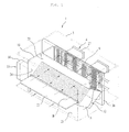
- FIG. 1 is a perspective view illustrating the first embodiment of the present invention
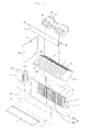
- FIG. 2 is an exploded perspective view illustrating the first embodiment of the present invention
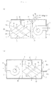
- FIG. 3a and FIG. 3b are side sectional views illustrating a simultaneous operation mode according to the first embodiment of the present invention.
- FIG. 4a and FIG. 4b are side sectional views illustrating a ventilating operation mode according to the first embodiment of the present invention.
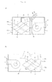
- FIG. 5a and FIG. 5b are side sectional views illustrating a cooling and heating operation mode according to the first embodiment of the present invention
- FIG. 6 is a perspective view illustrating the second embodiment of the present invention.
- FIG. 7 is an exploded perspective view illustrating the second embodiment of the present invention.
- FIG. 8 is a side sectional view illustrating a simultaneous operation mode according to the second embodiment of the present invention.
- FIG. 9 is a side sectional view illustrating a ventilation operation mode according to the second embodiment of the present invention.
- FIG. 10 is a side sectional view illustrating a cooling and heating operation mode according to the second embodiment of the present invention.
- a ventilating apparatus 1 includes a casing 3 constituting appearance, an air-supply fan unit 6 provided inside the casing 3, a heat exchanger 9 arranged at the rear of the air-supply fan unit 6, flowing a refrigerant therein, an pre-heat exchanger 12 provided to adjoin the heat exchanger 9, performing heat exchange between the room air and the outdoor air, and an air-exhaust fan unit 15 provided at one side of the pre-heat exchanger 12.
- a section plate 18 is provided between the air-exhaust fan unit 15 and the pre-heat exchanger 12 to section the air-exhaust fan unit 15 and the pre-heat exchanger from each other.
- the casing 3 is respectively provided with a first inlet 21 into which the room air flows, a second inlet 24 into which the outdoor air flows.
- the casing 3 is also provided with a first outlet 27 where an outlet side of the air-supply fan unit 6 is arranged, and a second outlet where an outlet side of the air-exhaust fan unit 15 is arranged.
- the first inlet 21 and the second inlet 24 are arranged up and down.
- the first inlet 21 is provided with a first switching damper that opens and closes the first inlet 21.
- a second switching damper 33 is provided between the second inlet 24 and the heat exchanger 9 to open and close a path formed between the second inlet 24 and the heat exchanger 9.
- the second switching damper 33 is rotatably arranged between an upper part inside the casing 1 and the pre-heat exchanger 12.
- the second switching damper 33 opens and closes a space between the second inlet 24 and the heat exchanger 9. In this case, it is possible to control the air flowing into the second inlet 24 so that the air directly flows to the heat exchanger 9 without passing through the pre-heat exchanger 12.
- a heat exchanger supporter 36 is provided at a side of a lower part of the heat exchanger 9 to support the heat exchanger 9.
- the first inlet 21, the pre-heat exchanger 12, the heat exchanger 9, and the air-supply fan unit 6 form an air-supply path A that supplies the outdoor air to the room.
- the second inlet 24, the pre-heat exchanger 12, and the air-exhaust fan unit 15 form an air-exhaust path B that exhausts the room air to the outside.
- the first and second inlets 21 and 24 and the air-supply fan unit 6 and the air-exhaust fan unit 15 are respectively connected with a duct (not shown).
- the air flows in and out along the duct with respect to the ventilating apparatus 1.
- the inside of the casing 3 is sectioned by the heat exchanger 9 and the heat exchanger supporter 36.
- the air-supply fan unit 6 is arranged in a part of the sectioned space, and the pre-heat exchanger 12 and the air-exhaust fan unit 15 are arranged in the other part of the sectioned space.
- the air-supply fan unit 6 includes an air-supply fan casing 6a, an air-supply fan 6b received in the air-supply fan casing 6a, and a driving device 6c rotatably driving the air-supply fan 6b.
- the air-exhaust fan unit 15 includes an air-exhaust fan casing 15a and an air-exhaust fan 15b received in the air-exhaust fan casing 15a.
- section plate 18 that sections the pre-heat exchanger 12 from the air-exhaust fan unit 15 is provided with a cutting part 18a formed in a type of an incline plane to serve as a moving path if the air exhausted from the pre-heat exchanger 12 moves to the air-exhaust fan unit 15.
- an incline angle of the cutting part 18a is provided to correspond to an incline part 12a formed at a side end of the pre-heat exchanger 12.
- an installation part 19 is formed at an upper part of the section plate 18.
- the installation part 19 is provided with a driving device 34 that rotates the second switching damper 33.
- the pre-heat exchanger 12 has a side section of a square shape, specifically a diamond shape.
- the pre-heat exchanger 12 includes a first path 13, and a second path 14 arranged to cross the first path 13. Boundary parts 12b and 12c are formed between the first path 13 and the second path 14.
- the first path 13 becomes a path that is connected from the front lower part to the rear upper part while the second path 14 becomes a path that is connected from the front upper part to the rear lower part.
- these paths cross each other in an X-shape.
- boundary parts 12b and 12c of the pre-heat exchanger 12 are arranged to respectively adjoin an inner wall of the casing 3, in which the first and second inlets 21 and 24 are arranged, and the heat exchanger supporter 36.
- Both sides of the pre-heat exchanger 12 should be laterally in contact with the inner wall of the casing 3 and the section plate 18 so as to prevent the wind from leaking out.
- the contact part may not form such a direct contact type. Namely, a separate sealing member (not shown) may be inserted to the contact part.
- first inlet 21 and the second inlet 24 are arranged to be spaced apart from each other at a given interval up and down as illustrated in FIG. 2 , it is preferable that the boundary part 12b adjoins the part between the first inlet 21 and the second inlet 24.
- the heat exchanger supporter 36 includes a first supporter 36a that supports the lower surface of the heat exchanger 9, and a second supporter 36b that supports a side of the heat exchanger 9.
- the heat exchanger supporter 36 is arranged as above so as to support the heat exchanger 9 and at the same time to prevent the air, which is to be flown to the outside, from adjoining to the heat exchanger 9, thereby avoiding heat-exchange between the heat exchanger 9 and the air.
- the operation mode of the ventilating apparatus includes a ventilating operation mode, a cooling and heating operation mode, and a simultaneous operation mode where the ventilating operation mode and the cooling and heating operation mode are simultaneously performed.
- the first switching damper 25 provided at the first inlet 21 is opened and at the same time the second switching damper 33 provided at the upper part of the pre-heat exchanger 12 is closed.
- the air-supply fan unit 6 and the air-exhaust fan unit 15 are operated in due order.
- the compressor connected with the ventilating apparatus is operated to transfer the refrigerant to refrigerant pipes 9a and 9b connected with the heat exchanger 9. Then, the refrigerant flows inside the heat exchanger 9.
- the outdoor air OA flows into the first inlet 21 and passes through the first path 13 provided in the pre-heat exchanger 12. Then, the air is exhausted to the room through the air-supply fan unit 6 after being exchanged with heat in the heat exchanger 9.
- the path where the outdoor air OA flows has been referred to as the air-supply path A.
- the air-supply path A includes the first inlet 21, and a path formed by flow of the air passing through the pre-beat exchanger 12, the heat exchanger 9 and the air-supply fan unit 6.
- the room air RA also flows toward the second inlet 24. After the air which has passed through the second inlet 24 passes through the second path 14 of the pre-heat exchanger 12, the air moves to the air-exhaust fan unit 15 and then is exhausted to the outside.
- the path where the room air RA flows has been referred to as the air-exhaust path B.
- the air-exhaust path B includes the second inlet 24, and a path formed by flow of the air passing through the pre-heat exchanger 12, and the air-exhaust fan unit 15.
- the room air RA and the outdoor air OA are mutually heat-exchanged in the pre-heat exchanger 12.
- FIG. 4a and FIG. 4b illustrate that the ventilating operation mode is selected.
- the refrigerant does not flow into the heat exchanger 9.
- the outdoor air OA and the room air RA are heat-exchanged in the pre-heat exchanger 12.
- the outdoor air OA flows along the air-supply path A while the room air RA flows along the air-exhaust path B.
- each element in the ventilating operation mode is the same as that of the simultaneous operation mode except that the refrigerant does not flow into the heat exchanger 9 and thus the outdoor air OA is not heat-exchanged in the heat exchanger 9. Accordingly, the detailed description of the operation of each element in the ventilating operation mode will be omitted.
- FIG. 5a and FIG. 5b illustrate that the cooling and heating operation mode is selected.
- the room air RA is not exhausted to the outside but circulates inside the room. Also, the outdoor air OA should not flow into the ventilating apparatus.
- the first inlet 21 is closed by the first switching damper 25 so as not to flow the outdoor air OA into the ventilating apparatus.
- the second switching damper 33 opens the space between the heat exchanger 9 and the second inlet 24 so that the room air RA directly moves to the heat exchanger 9 without passing through the pre-heat exchanger 12.
- the air-supply fan unit 6 should start to be operated, and the air-exhaust fan unit 15 should be stopped.
- the refrigerant is compressed in the compressor so that the air flown by the air-supply fan unit 6 is heat-exchanged in the heat exchanger 9. Then, the refrigerant flows into the heat exchanger 9 through the refrigerant pipes 9a and 9b.
- the room air circulates in the same manner as a general air-conditioner, whereby room-cooling or room-heating are performed.
- the ventilating apparatus includes a casing 103, an air-supply fan unit 106 provided inside the casing 103, a heat exchanger 109 arranged at the rear of the air-supply fan unit 106, and an air-exhaust fan unit 115 provided to adjoin the heat exchanger 109.
- An exhaust part of the air-supply fan unit 106 is arranged in a first outlet 127 provided at a side of the casing 103.
- the heat exchanger 109 should be arranged between the air-exhaust fan unit 115 and the air-supply fan unit 106.
- a pre-heat exchanger 112 is provided at one side of the air-exhaust fan unit 115 to perform heat exchange between the room air RA and the outdoor air OA.
- the casing 103 is provided with a first inlet 121 into which the outdoor air OA flows, and a second inlet 124 into which the room air RA flows.
- the first inlet 121 is provided with a first switching damper 125 that switches a flow of the air.
- the first inlet 121 and the second inlet 124 are arranged in parallel in left and right directions, and are spaced apart from each other.
- a second switching damper 133 is provided between the pre-heat exchanger 112 and an inner wall of the casing 103 to control a flow of the air, whereby the air flowing into the second inlet 124 directly flows into the heat exchanger 109.
- the pre-heat exchanger 112 has an upper section of a square shape, specifically a diamond shape. Also, it is preferable that a plurality of pre-heat exchangers 112 are provided to adjoin one another.
- the upper section of the pre-heat exchangers 112 has an arrangement where diamond shapes are continuously arranged.
- the pre-heat exchangers 112 are arranged in such a manner that their corners are linearly in contact with one another.
- a separate contact member that connects the respective pre-heat exchangers 112 with one another may preferably be provided.
- the pre-heat exchanger 112 is provided with a first path 113 through which the outdoor air OA passes and a second path 114 through which the room air RA passes.
- Boundary parts 112a and 112b are provided at the corner of the pre-heat exchanger 112, and form the boundary between the first path 113 and the second path 114.
- the boundary parts 112a and 112b should be arranged to adjoin the air-exhaust fan unit 115 and the casing 103. This is to allow the outdoor OA not to be mixed with the room air RA.
- the boundary part 112a of the boundary parts adjoins an air-exhaust fan casing 115a constituting appearance of the air-exhaust fan unit 115, and the other boundary part 112b adjoins a part between the first inlet 121 and the second inlet 124.
- the air-exhaust fan unit 115 is arranged to view the space formed between the boundary parts 112a of the respective pre-heat exchangers 112.
- the air-exhaust fan unit 115 includes the air-exhausting fan casing 115a, an exhausting fan 115b, and an exhaust duct 115c extended from the exhaust fan casing 115a.
- the exhaust duct 115c is connected to a second outlet 130 formed in the casing 103.
- the height of the exhaust duct 115c should be lower than the air-exhaust fan casing 115a. This is because that the outdoor air OA should flow above the exhaust duct 115c and then move to the heat exchanger 109.
- the contact part between the boundary part 112a of the pre-heat exchanger and the air-exhaust fan casing 115a and the contact part between the inner wall of the casing 103 and the boundary part 112b of the pre-heat exchanger are sealed such that the outdoor air OA is not mixed with the room air RA.
- the second switching damper 133 provided at both sides of the pre-heat exchanger 112 is spaced apart from the second inlet 124 at a given interval and rotatably arranged in the inner wall of the casing 103.
- the first switching damper 125 opens the first inlet 121, and at the same time the air-supply fan unit 106 and the air-exhaust fan unit 115 are operated.
- the second switching damper 133 should be closed, and the compressor supplies the refrigerant to the heat exchanger 109 while performing compression.
- the air-supply path A includes the first inlet 121, the first path 113 of the pre-heat exchanger 112, and a path forming a flow of the air between the heat exchanger 9 and the air-supply fan unit 106.
- the air-exhaust path B includes the second inlet 124, the second path 114 of the pre-heat exchanger 112, and a path forming a flow of the air between the heat exchanger and the air-exhaust fan unit 115.
- the outdoor air OA and the room air RA flow along their respective path, and are crossed with each other and heat-exchanged in the pre-heat exchanger 112. If the simultaneous operation mode is operated, ventilation and cooling and heating can be performed by one operation mode in due order.
- FIG. 9 illustrates that the ventilating operation mode is selected.
- the operation of each element in the ventilating operation mode is the same as that of the simultaneous operation mode except that the refrigerant does not flow into the heat exchanger 109 and thus heat exchange is not performed between the refrigerant and the outdoor air OA. Accordingly, the detailed description of the operation of each element in the ventilating operation mode will be omitted.
- FIG. 10 illustrates that the cooling and heating operation mode is selected. In this case, the air-supply fan unit 106 is operated but the air-exhaust fan unit is not operated.
- the second switching damper 133 is opened to connect the second inlet 124 with the heat exchanger 109.
- the compressor is operated to flow the refrigerant into the heat exchanger 109.
- the room air RA flows into the second inlet 124 like C by inflow action of the air and then directly moves to the heat exchanger 109, whereby the air is heat-exchanged with the refrigerant and then exhausted to the room through the air-supply fan unit 106.
- ventilation and cooling and heating are performed within a building and at the same time sizes of the units required for ventilation and cooling and heating can be minimized to improve space efficiency.
- the exhausted air is distributed at a uniform temperature. Also, air-conditioning can be performed suitably for a setting range of the user with respect to the fresh air from the outside. Accordingly, a comfortable room atmosphere can be obtained.
Landscapes
- Engineering & Computer Science (AREA)
- Chemical & Material Sciences (AREA)
- Combustion & Propulsion (AREA)
- Mechanical Engineering (AREA)
- General Engineering & Computer Science (AREA)
- Central Air Conditioning (AREA)
- Air-Flow Control Members (AREA)
- Air-Conditioning Room Units, And Self-Contained Units In General (AREA)
Applications Claiming Priority (1)
| Application Number | Priority Date | Filing Date | Title |
|---|---|---|---|
| KR1020080040991A KR101542372B1 (ko) | 2008-05-01 | 2008-05-01 | 환기장치 |
Publications (1)
| Publication Number | Publication Date |
|---|---|
| EP2113723A2 true EP2113723A2 (de) | 2009-11-04 |
Family
ID=40897453
Family Applications (1)
| Application Number | Title | Priority Date | Filing Date |
|---|---|---|---|
| EP09158815A Withdrawn EP2113723A2 (de) | 2008-05-01 | 2009-04-27 | Lüftungsvorrichtung |
Country Status (3)
| Country | Link |
|---|---|
| EP (1) | EP2113723A2 (de) |
| KR (1) | KR101542372B1 (de) |
| CN (1) | CN101571304B (de) |
Cited By (3)
| Publication number | Priority date | Publication date | Assignee | Title |
|---|---|---|---|---|
| CN102269462A (zh) * | 2010-06-02 | 2011-12-07 | 台达电子工业股份有限公司 | 空调系统及其空调设备 |
| WO2023276511A1 (ja) * | 2021-06-29 | 2023-01-05 | ダイキン工業株式会社 | 換気装置 |
| WO2023074499A1 (ja) * | 2021-10-29 | 2023-05-04 | ダイキン工業株式会社 | 換気装置 |
Families Citing this family (4)
| Publication number | Priority date | Publication date | Assignee | Title |
|---|---|---|---|---|
| CN102374601B (zh) * | 2011-10-15 | 2013-07-31 | 德华科电器科技(安徽)有限公司 | 一体式空调的节能型智能换新风系统 |
| KR101348786B1 (ko) * | 2013-08-08 | 2014-01-10 | 은성화학(주) | 냉난방장치 |
| CN105650798B (zh) * | 2016-03-07 | 2018-10-23 | 奥普家居股份有限公司 | 具有新风功能的换气装置 |
| KR102047754B1 (ko) | 2019-06-26 | 2019-11-22 | (주)엠티이에스 | 다기능 스마트 공조시스템 |
Family Cites Families (8)
| Publication number | Priority date | Publication date | Assignee | Title |
|---|---|---|---|---|
| JP3726802B2 (ja) * | 2002-11-28 | 2005-12-14 | 木村工機株式会社 | 床埋込形空調ユニット |
| CN100374791C (zh) * | 2002-12-06 | 2008-03-12 | Lg电子株式会社 | 通风设备的热交换系统 |
| KR100487381B1 (ko) | 2002-12-26 | 2005-05-03 | 엘지전자 주식회사 | 환기겸용 공기조화시스템 |
| KR100519310B1 (ko) * | 2003-06-11 | 2005-10-07 | 엘지전자 주식회사 | 급배기 직결형 환기겸용 공조시스템 |
| KR100628058B1 (ko) * | 2005-05-31 | 2006-09-27 | 엘지전자 주식회사 | 전열교환기 및 이를 이용한 환기시스템 |
| KR100628059B1 (ko) | 2005-05-31 | 2006-09-27 | 엘지전자 주식회사 | 전열교환기 및 이를 이용한 환기시스템 |
| JP4207166B2 (ja) * | 2006-08-17 | 2009-01-14 | 木村工機株式会社 | 除湿空調機 |
| JP4979308B2 (ja) * | 2006-08-28 | 2012-07-18 | 三機工業株式会社 | 空調システム |
-
2008
- 2008-05-01 KR KR1020080040991A patent/KR101542372B1/ko not_active Expired - Fee Related
-
2009
- 2009-04-27 EP EP09158815A patent/EP2113723A2/de not_active Withdrawn
- 2009-04-30 CN CN2009101322783A patent/CN101571304B/zh not_active Expired - Fee Related
Cited By (5)
| Publication number | Priority date | Publication date | Assignee | Title |
|---|---|---|---|---|
| CN102269462A (zh) * | 2010-06-02 | 2011-12-07 | 台达电子工业股份有限公司 | 空调系统及其空调设备 |
| WO2023276511A1 (ja) * | 2021-06-29 | 2023-01-05 | ダイキン工業株式会社 | 換気装置 |
| JP2023005637A (ja) * | 2021-06-29 | 2023-01-18 | ダイキン工業株式会社 | 換気装置 |
| WO2023074499A1 (ja) * | 2021-10-29 | 2023-05-04 | ダイキン工業株式会社 | 換気装置 |
| JP2023066689A (ja) * | 2021-10-29 | 2023-05-16 | ダイキン工業株式会社 | 換気装置 |
Also Published As
| Publication number | Publication date |
|---|---|
| CN101571304A (zh) | 2009-11-04 |
| KR20090115257A (ko) | 2009-11-05 |
| CN101571304B (zh) | 2012-08-29 |
| KR101542372B1 (ko) | 2015-08-06 |
Similar Documents
| Publication | Publication Date | Title |
|---|---|---|
| US7185510B2 (en) | Air conditioning and ventilating system | |
| JP6135705B2 (ja) | 利用側空調装置 | |
| EP2113723A2 (de) | Lüftungsvorrichtung | |
| KR101713546B1 (ko) | 일체형 환기 및 냉난방시스템 및 이를 이용한 환기 및 냉난방방법 | |
| KR20100128812A (ko) | 환기장치 및 환기장치의 제어방법 | |
| JP7227502B2 (ja) | 空調換気システム | |
| JP7457229B2 (ja) | 空気調和システム | |
| EP1632726B1 (de) | Klimaanlage zur Aufhängung an der Decke | |
| CN113811729A (zh) | 空调系统 | |
| EP2113725A2 (de) | Steuerverfahren für einen Lüfter | |
| CN212746725U (zh) | 窗式空调器 | |
| US20250093051A1 (en) | Outdoor unit of air conditioner | |
| CN218936486U (zh) | 空调器室内机 | |
| CN216844904U (zh) | 热交换新风机 | |
| JPH0914746A (ja) | 空気調和装置 | |
| JP3855393B2 (ja) | 空気調和装置 | |
| WO2020144769A1 (ja) | 空気調和装置 | |
| CN117561407B (zh) | 换气装置 | |
| KR100672602B1 (ko) | 공기조화장치의 실내 열교환유닛 | |
| JP2020186821A (ja) | 空気調和システム | |
| KR20110087894A (ko) | 열교환 환기 장치 | |
| JP2004144334A (ja) | 天井設置用一体形エアコン | |
| CN216522068U (zh) | 空气调节设备及系统 | |
| JP2011007345A (ja) | 換気装置 | |
| KR20040050560A (ko) | 환기겸용 냉난방시스템 및 이 시스템이 적용된 공기조화기 |
Legal Events
| Date | Code | Title | Description |
|---|---|---|---|
| PUAI | Public reference made under article 153(3) epc to a published international application that has entered the european phase |
Free format text: ORIGINAL CODE: 0009012 |
|
| 17P | Request for examination filed |
Effective date: 20090526 |
|
| AK | Designated contracting states |
Kind code of ref document: A2 Designated state(s): AT BE BG CH CY CZ DE DK EE ES FI FR GB GR HR HU IE IS IT LI LT LU LV MC MK MT NL NO PL PT RO SE SI SK TR |
|
| STAA | Information on the status of an ep patent application or granted ep patent |
Free format text: STATUS: THE APPLICATION HAS BEEN WITHDRAWN |
|
| 18W | Application withdrawn |
Effective date: 20120615 |