EP2113821B1 - Staubentferner für Computer und Steuerungsverfahren dafür - Google Patents
Staubentferner für Computer und Steuerungsverfahren dafür Download PDFInfo
- Publication number
- EP2113821B1 EP2113821B1 EP08166773.5A EP08166773A EP2113821B1 EP 2113821 B1 EP2113821 B1 EP 2113821B1 EP 08166773 A EP08166773 A EP 08166773A EP 2113821 B1 EP2113821 B1 EP 2113821B1
- Authority
- EP
- European Patent Office
- Prior art keywords
- vibration
- heat
- generating element
- main body
- computer
- Prior art date
- Legal status (The legal status is an assumption and is not a legal conclusion. Google has not performed a legal analysis and makes no representation as to the accuracy of the status listed.)
- Not-in-force
Links
Images


Classifications
-
- G—PHYSICS
- G06—COMPUTING OR CALCULATING; COUNTING
- G06F—ELECTRIC DIGITAL DATA PROCESSING
- G06F1/00—Details not covered by groups G06F3/00 - G06F13/00 and G06F21/00
- G06F1/16—Constructional details or arrangements
- G06F1/20—Cooling means
- G06F1/203—Cooling means for portable computers, e.g. for laptops
-
- F—MECHANICAL ENGINEERING; LIGHTING; HEATING; WEAPONS; BLASTING
- F28—HEAT EXCHANGE IN GENERAL
- F28G—CLEANING OF INTERNAL OR EXTERNAL SURFACES OF HEAT-EXCHANGE OR HEAT-TRANSFER CONDUITS, e.g. WATER TUBES OR BOILERS
- F28G7/00—Cleaning by vibration or pressure waves
-
- G—PHYSICS
- G06—COMPUTING OR CALCULATING; COUNTING
- G06F—ELECTRIC DIGITAL DATA PROCESSING
- G06F1/00—Details not covered by groups G06F3/00 - G06F13/00 and G06F21/00
-
- G—PHYSICS
- G06—COMPUTING OR CALCULATING; COUNTING
- G06F—ELECTRIC DIGITAL DATA PROCESSING
- G06F1/00—Details not covered by groups G06F3/00 - G06F13/00 and G06F21/00
- G06F1/16—Constructional details or arrangements
- G06F1/1601—Constructional details related to the housing of computer displays, e.g. of CRT monitors, of flat displays
-
- G—PHYSICS
- G06—COMPUTING OR CALCULATING; COUNTING
- G06F—ELECTRIC DIGITAL DATA PROCESSING
- G06F1/00—Details not covered by groups G06F3/00 - G06F13/00 and G06F21/00
- G06F1/16—Constructional details or arrangements
- G06F1/20—Cooling means
-
- H—ELECTRICITY
- H05—ELECTRIC TECHNIQUES NOT OTHERWISE PROVIDED FOR
- H05K—PRINTED CIRCUITS; CASINGS OR CONSTRUCTIONAL DETAILS OF ELECTRIC APPARATUS; MANUFACTURE OF ASSEMBLAGES OF ELECTRICAL COMPONENTS
- H05K7/00—Constructional details common to different types of electric apparatus
- H05K7/20—Modifications to facilitate cooling, ventilating, or heating
- H05K7/20009—Modifications to facilitate cooling, ventilating, or heating using a gaseous coolant in electronic enclosures
- H05K7/20136—Forced ventilation, e.g. by fans
- H05K7/20181—Filters; Louvers
Definitions
- the present invention relates to a computer, and more particularly, to a dust eliminator for eliminating dust and foreign substance adhering to a cooling fin, and a control method thereof.
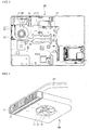
- FIG. 1 is a perspective view showing an external appearance of a general computer
- FIG. 2 is a plan view showing the internal configuration of the computer.
- a computer 1 generally comprises a main body 3 and a display unit 5.
- the display unit 5 is provided with a display screen 6 having a liquid crystal panel, and is connected to a rear portion of the main body 3 to be brought into contact with an upper surface of the man body 3 or unfolded with respect thereto.
- the display unit 5 is formed in the shape of a generally flat hexahedral plate.
- the main body 3 is in the shape of a generally flat hexahedral plate, a key board section 7 is provided on the upper surface of the main body.
- a ventilating hole 9 is formed on one side of an outer surface of the main body 3 to exhaust heat generated in the main body to the outside. Air stream containing heat generated in the main body 3 passes through the ventilating hole 9.
- a main board 10 is installed in the main body 3.
- a plurality of heat-generating elements 11 are mounted on the main board 10.
- the heat-generating elements 11 include, for example, a microprocessor, a chipset, a graphic chip and the like.
- a heat-radiating fan 20 is provided in the main body 3 to exhaust heat generated from the heat-generating components 11 to the outside.
- the heat-radiating fan 20 serves to form air stream directed toward the ventilating hole 9 in the main body 3.
- a cooling fin 23 is provided between the ventilating hole 9 and the heat-radiating fan 20.
- a plurality of fin gaps through which air stream can pass are formed on the cooling fin 23.
- One ends of heat pipes 25 are in thermal contact with an upper surface of the cooling fin 23.
- the other ends of the hat pipes 25 are in thermal contact with the heat-generating components 11.
- the heat pipes 25 serve to transfer heat of the heat-generating components 11 to the cooling fin 23.
- Air stream to be exhausted to the outside via the ventilating hole 9 is formed by the driving of the heat-radiating fan 20. At this time, the air stream, which contains the heat transferred from the cooling fin 23 to the air stream while the air stream passes through the cooling fin 23, is exhausted to the outside.
- a filter is installed at a location adjacent to the cooling fin 23 for filtering dust.
- a user should replace or wash the filter used.
- JP 2006 332377 A describes a cooling structure for an electronic component, wherein the vibration of a vibration source prevents the adhesion of dust to a heat sink.
- the present invention is conceived to solve the aforementioned problems in a related art.
- An object of the present invention is to automatically eliminate dust accumulated on a cooling fine of a computer to keep the cooling fin clean.
- Another object of the present invention is to easily clean a cooling fin of a computer.
- a computer having a dust eliminator according to claim 1.
- a driving duration of the vibration-generating element and the number of times the vibration-generating element is driven may be controlled by the control unit.
- the vibration-generating element is a piezoelectric element provided at one side of the cooling fin.
- the vibration-generating element may be driven for a predetermined time from an initial time at which the main body is required to be powered on.
- the vibration-generating element is driven for a predetermined time from an initial time at which the main body is required to be powered off.
- the vibration-generating element may be driven for a predetermined time whenever the main body is required to be powered on and powered off.
- a computer according to the present invention as described above in detail can obtain the following effects.
- vibration of the vibration-generating element attached to the cooling fin causes dust accumulated on the cooling fin to be shaken off, and the dust separated from the cooling fin is then exhausted out of the main body along with air stream formed by the heat-radiating fan.
- the driving of the vibration-generating element is controlled by the control unit of the main body. Accordingly, there are advantageous effects in that the cooling fin is always kept clean and heat exchange is well performed by the cooling fin to thereby enhance the cooling efficient of the main body.
- the cooling fin is easily cleaned to thereby increase the convenience in use.
- FIG. 3 is a plan view showing the internal configuration of a computer according to the present invention
- FIG. 4 is a perspective view showing the configuration of a dust eliminator for the computer according to the present invention
- FIG. 5 is a block diagram illustrating the operation of the dust eliminator for the computer according to the present invention.
- a ventilating hole 32 is formed on one side of a main body 30 of the computer.
- the ventilating hole 32 causes interior and exterior of the main body 30 to communicate with each other.
- a plurality of heat-generating components 33 are provided inside of the main body 30.
- the above heat-generating components 33 include a chipset, a control unit 40 to be described below, and the like.
- the control unit 40 is provided in the main body 30.
- the control unit 40 is also called as a central processing unit (CPU).
- the control unit 40 processes all kinds of signals to control various components of the main body 30.
- the control unit 40 controls driving of a heat-radiating fan 50, which will be described later.
- the control unit 40 detects a temperature in the main body 30, or detects the active operation of the main body 30, to thereby drive the heat-radiating fan 50. It will be apparent that the control unit 40 can periodically drive the heat-radiating fan 50.
- control unit 40 serves to control driving of a vibration-generating element 70 to be described later. This will be illustrated in more detail later.
- the heat-radiating fan 50 is provided at a location adjacent to the ventilating hole 32.
- the heat-radiating fan 50 serves to form a certain air stream inside of the main body 30.
- the heat-radiating fan 50 comprises a fan housing 51 and rotating blades 52, wherein a suction hole 53 is formed on one surface of the fan housing 51.
- a discharging hole (not shown) is formed on a side surface of the fan housing 51, that is, on a portion opposite to the ventilating hole 32, so that air sucked through the suction hole 53 is exhausted through the discharging hole by rotation of the rotating blades 52.
- a cooling fin 60 is provided between the ventilating hole 32 and the heat-radiating fan 50.
- the cooling fin 60 is configured such that air can pass through the cooling fin. In other words, a plurality of micro gaps are formed in the cooling fin 60.
- the cooling fin 60 is placed between the discharging hole of the fan housing 51. and the ventilating hole 32, thereby allowing heat-exchange to be performed while air discharged from the discharging hole flows to the ventilating hole 32.
- the vibration-generating element 70 is provided at one side of the cooling fin 60.
- the vibration-generating element 70 serves to transmit vibration to the cooling fin 60 to thereby shake off fine dusts accumulated on the cooling fin 60.
- the vibration-generating element 70 includes a piezoelectric element, a vibration motor and the like.
- the piezoelectric element is changed in shape according to an electrical signal to generate vibration when electric power is applied to the piezoelectric element.
- the vibration motor is a motor for converting an electrical energy into a mechanical vibration energy using a principle of generating electromagnetic force.
- the vibration-generating element 70 is attached to a lower surface of the cooling fin 60. More specifically, the vibration-generating element 70 is attached to the surface of the cooling fin 60 that is opposite to a surface thereof contacting with a heat pipe 80 to be described later. However, since the vibration-generating element 70 sufficiently functions in it can transmit vibration to the cooling fin 60, there is no necessarily need to attach the vibration-generating element to the lower surface of the cooling fin 60. It is only preferable that the vibration-generating element 70 be provided at a position such that the gaps through which air stream can pass are not blocked and an interference with the heat pipe 80 is not generated.
- the heat pipe 80 serves to transfer heat generated in the heat-generating components 33 to the cooling fin 60. To this end, both ends of the heat pipe 80 are in thermal contact with the heat-generating components 33 and the cooling fin 60, respectively,
- a power supplying unit 90 serves to supply power to the main body 30.
- a switch 92 is provided between the power supplying unit 90 and the vibration-generating element 70, and the switch 92 is operated according to the signal of the control unit 40. That is, the switch 92 is operated according to the signal of the control unit 40 and thus the power of the power supplying unit 90 is selectively transmitted to the vibration-generating element 70, so that the driving of the vibration-generating element 70 is controlled.
- the information for determining the number of times the vibration-generating member 70 is driven, a driving timing of the vibration-generating member 70, or a duration for each driving of the vibration-generating member 70 may be inputted into the control unit 40 in advance.
- the information is stored in the control unit 40 so that the vibration-generating element 70 can be driven for a certain time from an initial time at which electric power is supplied to the main body 30.
- the vibration-generating element 70 may be driven several times periodically at regular intervals, may be driven in cooperation with the driving of the heat-radiating fan 50 and may be operated according to the temperature of the heat-generating components 33.
- the vibration-generating element 70 is driven by residual power in the main body 30 to transmit vibration to the cooling fin 60. This is to minimize vibration transmitted to the cooling fin 60 while the user substantially operates the computer, thereby not preventing the user from using the computer.
- An AC/DC converter 94 serves to convert the power supplied from the power supplying unit 90 into power suitable for the vibration-generating element 70.
- the heat-radiating fan 50 In order to radiate the heat generated in a process of operating the computer, the heat-radiating fan 50 is driven. Air sucked through the suction hole 53 by the driving of the heat-radiating fan 50 passes through the cooling fin 60 and then exhausted to the outside through the ventilating hole 32a, wherein while the air passes through the cooling fin 60, heat is exchanged therebetween.
- the heat generated in the heat-generating components 33 is transferred to the cooling fin 60 through the heat pipe 80. Then, the cooling fin 60, whose temperature has been raised by the heat pipe 80, is cooled through a heat transferring process between the cooling fin 60 and the air passing therethrough.
- the cooling fin 60 is covered with foreign substance or dust contained in the air passing through the cooling fin 60. If the dust is accumulated on the cooling fin 60, the air stream generated by the heat-radiating fan 50 cannot smoothly pass through the cooling fin 60, so that the heat exchange does not occur sufficiently.
- the vibration-generating element 70 attached to the lower surface of the cooling fin 60 vibrates the cooling fin 60, thereby causing dust accumulated on the cooling fin 60 to be separated therefrom. Then, the air stream generated by the heat-radiating fan 50 is exhausted to the outside together with the dust separated from the cooling fin 50.
- the driving of the vibration-generating element 70 is controlled by the control unit 40. More specifically, the control unit 40 operates the switch 92, so that the power supplied from the power supplying unit 90 to the vibration-generating element 70 is adjusted to thereby control the driving of the vibration-generating element 70. In addition, the driving of the vibration-generating element 70 may be in cooperation with the driving of the heat-radiating fan 50.
- the information for operating the switch 92 is stored in the control unit 40 in advance.
- the vibration-generating element 70 is driven for a certain time when the main body 30 is required to be powered on or the main body 30 is required to be powered off.
- the vibration-generating element 70 can be driven for a certain time whenever the main body 30 is required to be powered on and powered off.
- the rotating blades 52 provided in the heat-radiating fan 50 are rotated at the highest rotating speed while the vibration-generating element 70 is supplied with power. This is to eliminate the dust, which is separated from the cooling fin 60 by the vibration of the vibration-generating element 70, by stronger air stream.
- a rotating speed of the rotating blades 52 provided in the heat-radiating fan 50 may be varied while the vibration-generating element 70 is supplied with power. This is to eliminate the dust, which is separated from the cooling fin 60, by air stream with a varied strength.
- the vibration-generating element 70 is supplied with power for a certain time when the detected temperature of the heat-generating element 33 provided in the main body 30, particularly, the detected temperature of the CPU according to use of the CPU exceeds the allowable temperature. Allowable temperature ranges of the CPU according to use of the CPU are listed at the following table. Referring to the table, since an allowable temperature range of the CPU is 30 ⁇ 50 °C when the use of the CPU is 20%, the vibration-generating element 70 is supplied with power while the detected temperature exceeds 50 °C. Table 1.
- Allowable temperature range of CPU according to use of CPU Use of CPU (%) Allowable temperature range of CPU(°C) 0 ⁇ 20% 30 ⁇ 50 °C 20 ⁇ 50% 40 ⁇ 65 °C 50 ⁇ 90% 55 ⁇ 75 °C 90 ⁇ 100% 65 ⁇ 85 °C
- the vibration-generating element 70 is periodically supplied with power. That is, the vibration-generating element 70 may be supplied with power once a week or once a month.
- a rotating speed of the rotating blades 52 provided in the heat-radiating fan 50 is detected, and then, the vibration-generating element 70 is supplied with power for a certain time when the rotating speed of the rotating blades is a maximum value.
Landscapes
- Engineering & Computer Science (AREA)
- Theoretical Computer Science (AREA)
- Physics & Mathematics (AREA)
- General Engineering & Computer Science (AREA)
- General Physics & Mathematics (AREA)
- Microelectronics & Electronic Packaging (AREA)
- Human Computer Interaction (AREA)
- Computer Hardware Design (AREA)
- Thermal Sciences (AREA)
- Chemical & Material Sciences (AREA)
- Combustion & Propulsion (AREA)
- Mechanical Engineering (AREA)
- Cooling Or The Like Of Electrical Apparatus (AREA)
Claims (3)
- Computer, der aufweist:einen Hauptkörper (30) mit einem Innenraum und einer Belüftungsöffnung (32);eine Steuerungseinheit (40) in dem Hauptkörper (30);eine Stromversorgungseinheit (90) zum Versorgen des Hauptkörpers (30) mit Strom;undeinen Staubentferner, wobei der Staubentferner aufweist:einen wärmeableitenden Lüfter (50), der im Innenraum des Hauptkörpers (30) vorgesehen ist, um einen Luftstrom nach draußen für Abwärme im Hauptkörper (30) zu bilden;eine Kühleinrichtung (60) mit einer Vielzahl darin ausgebildeten Mikrospalten, so dass Luft hindurchfließen kann, wobei die Kühleinrichtung (60) zwischen der Belüftungsöffnung (32) und dem wärmeableitenden Lüfter (50) vorgesehen ist, und die Kühleinrichtung (60) mit dem durchfließenden Luftstrom Wärme tauscht;ein schwingungserzeugendes Element (70), das Schwingung zur Kühleinrichtung (60) überträgt, um auf der Kühleinrichtung (60) angesammelten Staub abzuschütteln;wobei der Computer ferner einen Schalter (92) aufweist, um, auf ein Signal der Steuerungseinheit (40) hin, das schwingungserzeugende Element (70) gezielt mit Strom von der Stromversorgungseinheit (90) zu versorgen, und gekennzeichnet ist durch:ein Wärmerohr (80), das mit einer Oberfläche der Kühleinrichtung (60) in Kontakt steht, um die Wärme, die in einem in dem Hauptkörper (30) vorgesehenen wärmeerzeugenden Bauteil (33) erzeugt wird, zur Kühleinrichtung (60) zu leiten, wobei das schwingungserzeugende Element (70) in Kontakt mit einer Oberfläche der Kühleinrichtung (60) steht, die gegenüber der Oberfläche liegt, die in Kontakt mit dem Wärmerohr (80) ist,wobei das schwingungserzeugende Element eine bestimmte Zeit lang in der Anfangszeit, in der der Computer ausgeschalten werden soll, angetrieben wird, um die zu der Kühleinrichtung (60) übertragene Schwingung zu minimieren, während der Nutzer den Computer bedient,wobei eine Drehgeschwindigkeit einer in dem wärmeableitenden Lüfter (50) vorgesehenen rotierenden Lamelle auf Höchstgeschwindigkeit läuft oder variiert, während das schwingungserzeugende Element angetrieben wird.
- Computer nach Anspruch 1, wobei das schwingungserzeugende Element (70) ein piezoelektrisches Element ist.
- Computer nach Anspruch 1, wobei das schwingungserzeugende Element (70) ein Vibrationsmotor ist.
Applications Claiming Priority (1)
| Application Number | Priority Date | Filing Date | Title |
|---|---|---|---|
| KR20080041492A KR101494007B1 (ko) | 2008-05-02 | 2008-05-02 | 컴퓨터의 먼지제거장치 및 그 제어방법 |
Publications (3)
| Publication Number | Publication Date |
|---|---|
| EP2113821A2 EP2113821A2 (de) | 2009-11-04 |
| EP2113821A3 EP2113821A3 (de) | 2009-11-25 |
| EP2113821B1 true EP2113821B1 (de) | 2017-05-03 |
Family
ID=40905114
Family Applications (1)
| Application Number | Title | Priority Date | Filing Date |
|---|---|---|---|
| EP08166773.5A Not-in-force EP2113821B1 (de) | 2008-05-02 | 2008-10-16 | Staubentferner für Computer und Steuerungsverfahren dafür |
Country Status (4)
| Country | Link |
|---|---|
| US (1) | US8400766B2 (de) |
| EP (1) | EP2113821B1 (de) |
| KR (1) | KR101494007B1 (de) |
| CN (1) | CN101571732B (de) |
Families Citing this family (29)
| Publication number | Priority date | Publication date | Assignee | Title |
|---|---|---|---|---|
| US9228785B2 (en) | 2010-05-04 | 2016-01-05 | Alexander Poltorak | Fractal heat transfer device |
| US10852069B2 (en) | 2010-05-04 | 2020-12-01 | Fractal Heatsink Technologies, LLC | System and method for maintaining efficiency of a fractal heat sink |
| TW201144982A (en) * | 2010-06-09 | 2011-12-16 | Hon Hai Prec Ind Co Ltd | Computer capable of automatically cleaning dust |
| CN102279620A (zh) * | 2010-06-10 | 2011-12-14 | 鸿富锦精密工业(深圳)有限公司 | 具有自动除尘功能的电脑设备 |
| WO2012014640A1 (en) * | 2010-07-26 | 2012-02-02 | Canon Kabushiki Kaisha | Vibration wave motor |
| US8709140B2 (en) | 2011-03-29 | 2014-04-29 | Hewlett-Packard Development Company, L.P. | Particulate removal |
| CN103157626B (zh) * | 2011-12-13 | 2016-10-05 | 技嘉科技股份有限公司 | 除尘装置 |
| CN103433247B (zh) * | 2013-08-07 | 2016-03-30 | 华为数字技术(苏州)有限公司 | 电子设备除尘方法、装置和电子设备 |
| US9459669B2 (en) * | 2014-01-28 | 2016-10-04 | Dell Products L.P. | Multi-component shared cooling system |
| US20170059263A1 (en) * | 2014-03-31 | 2017-03-02 | Intel Corporation | Sonic dust remediation |
| JP6323175B2 (ja) * | 2014-05-29 | 2018-05-16 | 富士通株式会社 | 電子機器およびフィルタ装置 |
| CN105222105A (zh) * | 2014-06-12 | 2016-01-06 | 奇鋐科技股份有限公司 | Led灯具除尘散热系统 |
| CN104438223A (zh) * | 2014-12-01 | 2015-03-25 | 广西大学 | 电脑除尘器 |
| HK1249161A1 (zh) * | 2015-05-20 | 2018-10-26 | 菲舍尔和佩克尔应用有限公司 | 风扇或泵布置和操作方法 |
| TWI536152B (zh) * | 2015-05-26 | 2016-06-01 | 鴻海精密工業股份有限公司 | 除塵結構及具有該除塵結構的電子系統 |
| JP6227610B2 (ja) * | 2015-10-02 | 2017-11-08 | ファナック株式会社 | 放熱フィンの目詰まりを検知する機能を有する冷却装置 |
| US10830545B2 (en) * | 2016-07-12 | 2020-11-10 | Fractal Heatsink Technologies, LLC | System and method for maintaining efficiency of a heat sink |
| WO2019018446A1 (en) | 2017-07-17 | 2019-01-24 | Fractal Heatsink Technologies, LLC | SYSTEM AND METHOD FOR MULTI-FRACTAL THERMAL DISSIPATOR |
| EP3539671A1 (de) * | 2018-03-14 | 2019-09-18 | Nokia Technologies Oy | Laden eines elektrisch leitfähigen objekts |
| CN110948140A (zh) * | 2018-09-26 | 2020-04-03 | 天津龙净环保科技有限公司 | 一种栏杆焊接辅助机器人 |
| CN111054668B (zh) * | 2019-11-20 | 2020-11-24 | 浙江无极互联科技有限公司 | 一种电脑主机箱清尘装置 |
| CN111799928B (zh) * | 2020-07-15 | 2021-10-12 | 重庆新登奇机电技术有限公司 | 一种具有散热功能的工业机器人电机箱体 |
| US11924994B2 (en) * | 2021-07-16 | 2024-03-05 | Dell Products L.P. | Managing a heatsink of an information handling system |
| CN113663332A (zh) * | 2021-08-27 | 2021-11-19 | 努比亚技术有限公司 | 一种风扇除尘控制方法、设备及计算机可读存储介质 |
| CN114302592B (zh) * | 2021-12-27 | 2024-05-03 | 上海宝创网络科技有限公司 | 一种用于IPv6软件定义转发的网络加速卡 |
| CN114630569B (zh) * | 2022-03-18 | 2025-02-11 | 安徽省三荣科技有限公司 | 一种用于地源热泵空调系统的能效监测装置 |
| CN114629399B (zh) * | 2022-03-22 | 2023-01-31 | 江苏久祥汽车电器集团有限公司 | 一种环保型汽车发电机调节器支架 |
| TWI817473B (zh) * | 2022-04-28 | 2023-10-01 | 宏碁股份有限公司 | 散熱系統 |
| CN117251342B (zh) * | 2023-11-17 | 2024-02-06 | 合肥天帷信息安全技术有限公司 | 一种基于大数据的网络监测设备 |
Family Cites Families (14)
| Publication number | Priority date | Publication date | Assignee | Title |
|---|---|---|---|---|
| US6100654A (en) * | 1998-01-29 | 2000-08-08 | Canon Kabushiki Kaisha | Driving device for a vibration type motor |
| DE19916595B4 (de) * | 1999-04-13 | 2005-03-31 | Siemens Ag | Anordnung zum Kühlen einer elektrischen Baugruppe und zum Kühlen eines elektrisch betriebenen technischen Gerätes |
| KR100465793B1 (ko) * | 2002-06-20 | 2005-01-13 | 삼성전자주식회사 | 컴퓨터 |
| JP2004219852A (ja) | 2003-01-17 | 2004-08-05 | Hitachi Ltd | 投射型映像表示装置及びこれに用いる偏光板装置 |
| EP1531384A3 (de) * | 2003-11-14 | 2006-12-06 | LG Electronics Inc. | Kühlvorrichtung für tragbaren Rechner |
| JP2007266020A (ja) | 2004-03-26 | 2007-10-11 | Nec Corp | 電子機器の空冷方法および装置 |
| TWM270405U (en) * | 2004-08-19 | 2005-07-11 | Compal Electronics Inc | Heat sink device with dust-collection mechanism |
| TWI247190B (en) * | 2004-11-09 | 2006-01-11 | Coretronic Corp | Self dust-off apparatus and method thereof |
| JP4507984B2 (ja) | 2005-05-26 | 2010-07-21 | 富士通株式会社 | 冷却構造 |
| TWI265271B (en) | 2005-09-15 | 2006-11-01 | Asustek Comp Inc | Thermal module capable of dusting fins off by vibration and electronic appliance thereof |
| JP4493611B2 (ja) | 2005-12-13 | 2010-06-30 | 富士通株式会社 | 電子機器 |
| TWI309748B (en) * | 2006-03-01 | 2009-05-11 | Chien Holdings Llc | Electronic device and filter unit |
| TW200823636A (en) * | 2006-11-23 | 2008-06-01 | Inventec Corp | Heat-dissipation device with dust-disposal function |
| TW200823637A (en) * | 2006-11-23 | 2008-06-01 | Inventec Corp | Heat-dissipation device having dust-disposal mechanism |
-
2008
- 2008-05-02 KR KR20080041492A patent/KR101494007B1/ko not_active Expired - Fee Related
- 2008-09-29 US US12/240,941 patent/US8400766B2/en not_active Expired - Fee Related
- 2008-10-16 EP EP08166773.5A patent/EP2113821B1/de not_active Not-in-force
- 2008-11-14 CN CN2008101782068A patent/CN101571732B/zh not_active Expired - Fee Related
Also Published As
| Publication number | Publication date |
|---|---|
| US8400766B2 (en) | 2013-03-19 |
| EP2113821A3 (de) | 2009-11-25 |
| KR101494007B1 (ko) | 2015-02-16 |
| EP2113821A2 (de) | 2009-11-04 |
| US20090272404A1 (en) | 2009-11-05 |
| CN101571732B (zh) | 2013-02-27 |
| CN101571732A (zh) | 2009-11-04 |
| KR20090115571A (ko) | 2009-11-05 |
Similar Documents
| Publication | Publication Date | Title |
|---|---|---|
| US8400766B2 (en) | Dust eliminator for computer and control method thereof | |
| US20080121373A1 (en) | Heat-dissipation device with dust-disposal function | |
| US8256495B2 (en) | Electronic apparatus including removable dust catcher | |
| JP4675666B2 (ja) | 電子機器 | |
| US8203840B2 (en) | Self-cleaning computer | |
| EP2306265B1 (de) | Computer mit Kühlvorrichtung | |
| CN102762080A (zh) | 电子装置 | |
| CN103419162B (zh) | 电动工具 | |
| JP4697307B2 (ja) | 冷却装置、電子機器及び送風装置 | |
| CN102279620A (zh) | 具有自动除尘功能的电脑设备 | |
| JP3738191B2 (ja) | 電子カメラの冷却装置固定構造 | |
| JP5507095B2 (ja) | ファンフィルターユニット、半導体製造装置、フラットパネルディスプレイ製造装置および清浄化空気の製造方法 | |
| US20040191057A1 (en) | [cooling fan with dust-filtering function] | |
| JP2000252669A (ja) | 冷却装置および電子機器 | |
| JP2008140943A (ja) | 情報処理装置 | |
| JP2004200361A (ja) | 空冷電気装置 | |
| JPH07239390A (ja) | 電子機器 | |
| JP2007266020A (ja) | 電子機器の空冷方法および装置 | |
| JP2008311276A (ja) | 電子機器 | |
| CN221983240U (zh) | 一种电机控制柜除尘装置 | |
| CN221301581U (zh) | 一种实验室用换气装置 | |
| JPH10314423A (ja) | 遊技機用制御装置 | |
| JPH0444297A (ja) | 送風ファンの使用法 | |
| CN221846521U (zh) | 一种环保工程用有害气体处理装置 | |
| JPH05238111A (ja) | 電子機器の内部冷却装置 |
Legal Events
| Date | Code | Title | Description |
|---|---|---|---|
| PUAI | Public reference made under article 153(3) epc to a published international application that has entered the european phase |
Free format text: ORIGINAL CODE: 0009012 |
|
| PUAL | Search report despatched |
Free format text: ORIGINAL CODE: 0009013 |
|
| AK | Designated contracting states |
Kind code of ref document: A2 Designated state(s): AT BE BG CH CY CZ DE DK EE ES FI FR GB GR HR HU IE IS IT LI LT LU LV MC MT NL NO PL PT RO SE SI SK TR |
|
| AX | Request for extension of the european patent |
Extension state: AL BA MK RS |
|
| AK | Designated contracting states |
Kind code of ref document: A3 Designated state(s): AT BE BG CH CY CZ DE DK EE ES FI FR GB GR HR HU IE IS IT LI LT LU LV MC MT NL NO PL PT RO SE SI SK TR |
|
| AX | Request for extension of the european patent |
Extension state: AL BA MK RS |
|
| 17P | Request for examination filed |
Effective date: 20100413 |
|
| 17Q | First examination report despatched |
Effective date: 20100616 |
|
| AKX | Designation fees paid |
Designated state(s): AT BE BG CH CY CZ DE DK EE ES FI FR GB GR HR HU IE IS IT LI LT LU LV MC MT NL NO PL PT RO SE SI SK TR |
|
| APBK | Appeal reference recorded |
Free format text: ORIGINAL CODE: EPIDOSNREFNE |
|
| APBN | Date of receipt of notice of appeal recorded |
Free format text: ORIGINAL CODE: EPIDOSNNOA2E |
|
| APBR | Date of receipt of statement of grounds of appeal recorded |
Free format text: ORIGINAL CODE: EPIDOSNNOA3E |
|
| APAF | Appeal reference modified |
Free format text: ORIGINAL CODE: EPIDOSCREFNE |
|
| APBT | Appeal procedure closed |
Free format text: ORIGINAL CODE: EPIDOSNNOA9E |
|
| GRAP | Despatch of communication of intention to grant a patent |
Free format text: ORIGINAL CODE: EPIDOSNIGR1 |
|
| INTG | Intention to grant announced |
Effective date: 20161221 |
|
| GRAS | Grant fee paid |
Free format text: ORIGINAL CODE: EPIDOSNIGR3 |
|
| GRAA | (expected) grant |
Free format text: ORIGINAL CODE: 0009210 |
|
| AK | Designated contracting states |
Kind code of ref document: B1 Designated state(s): AT BE BG CH CY CZ DE DK EE ES FI FR GB GR HR HU IE IS IT LI LT LU LV MC MT NL NO PL PT RO SE SI SK TR |
|
| REG | Reference to a national code |
Ref country code: GB Ref legal event code: FG4D |
|
| REG | Reference to a national code |
Ref country code: AT Ref legal event code: REF Ref document number: 890657 Country of ref document: AT Kind code of ref document: T Effective date: 20170515 Ref country code: CH Ref legal event code: EP |
|
| REG | Reference to a national code |
Ref country code: IE Ref legal event code: FG4D |
|
| REG | Reference to a national code |
Ref country code: DE Ref legal event code: R096 Ref document number: 602008050027 Country of ref document: DE |
|
| REG | Reference to a national code |
Ref country code: NL Ref legal event code: MP Effective date: 20170503 |
|
| REG | Reference to a national code |
Ref country code: FR Ref legal event code: PLFP Year of fee payment: 10 |
|
| REG | Reference to a national code |
Ref country code: AT Ref legal event code: MK05 Ref document number: 890657 Country of ref document: AT Kind code of ref document: T Effective date: 20170503 |
|
| REG | Reference to a national code |
Ref country code: LT Ref legal event code: MG4D |
|
| PG25 | Lapsed in a contracting state [announced via postgrant information from national office to epo] |
Ref country code: GR Free format text: LAPSE BECAUSE OF FAILURE TO SUBMIT A TRANSLATION OF THE DESCRIPTION OR TO PAY THE FEE WITHIN THE PRESCRIBED TIME-LIMIT Effective date: 20170804 Ref country code: HR Free format text: LAPSE BECAUSE OF FAILURE TO SUBMIT A TRANSLATION OF THE DESCRIPTION OR TO PAY THE FEE WITHIN THE PRESCRIBED TIME-LIMIT Effective date: 20170503 Ref country code: ES Free format text: LAPSE BECAUSE OF FAILURE TO SUBMIT A TRANSLATION OF THE DESCRIPTION OR TO PAY THE FEE WITHIN THE PRESCRIBED TIME-LIMIT Effective date: 20170503 Ref country code: NO Free format text: LAPSE BECAUSE OF FAILURE TO SUBMIT A TRANSLATION OF THE DESCRIPTION OR TO PAY THE FEE WITHIN THE PRESCRIBED TIME-LIMIT Effective date: 20170803 Ref country code: AT Free format text: LAPSE BECAUSE OF FAILURE TO SUBMIT A TRANSLATION OF THE DESCRIPTION OR TO PAY THE FEE WITHIN THE PRESCRIBED TIME-LIMIT Effective date: 20170503 Ref country code: LT Free format text: LAPSE BECAUSE OF FAILURE TO SUBMIT A TRANSLATION OF THE DESCRIPTION OR TO PAY THE FEE WITHIN THE PRESCRIBED TIME-LIMIT Effective date: 20170503 Ref country code: FI Free format text: LAPSE BECAUSE OF FAILURE TO SUBMIT A TRANSLATION OF THE DESCRIPTION OR TO PAY THE FEE WITHIN THE PRESCRIBED TIME-LIMIT Effective date: 20170503 |
|
| PG25 | Lapsed in a contracting state [announced via postgrant information from national office to epo] |
Ref country code: PL Free format text: LAPSE BECAUSE OF FAILURE TO SUBMIT A TRANSLATION OF THE DESCRIPTION OR TO PAY THE FEE WITHIN THE PRESCRIBED TIME-LIMIT Effective date: 20170503 Ref country code: IS Free format text: LAPSE BECAUSE OF FAILURE TO SUBMIT A TRANSLATION OF THE DESCRIPTION OR TO PAY THE FEE WITHIN THE PRESCRIBED TIME-LIMIT Effective date: 20170903 Ref country code: LV Free format text: LAPSE BECAUSE OF FAILURE TO SUBMIT A TRANSLATION OF THE DESCRIPTION OR TO PAY THE FEE WITHIN THE PRESCRIBED TIME-LIMIT Effective date: 20170503 Ref country code: SE Free format text: LAPSE BECAUSE OF FAILURE TO SUBMIT A TRANSLATION OF THE DESCRIPTION OR TO PAY THE FEE WITHIN THE PRESCRIBED TIME-LIMIT Effective date: 20170503 Ref country code: BG Free format text: LAPSE BECAUSE OF FAILURE TO SUBMIT A TRANSLATION OF THE DESCRIPTION OR TO PAY THE FEE WITHIN THE PRESCRIBED TIME-LIMIT Effective date: 20170803 Ref country code: NL Free format text: LAPSE BECAUSE OF FAILURE TO SUBMIT A TRANSLATION OF THE DESCRIPTION OR TO PAY THE FEE WITHIN THE PRESCRIBED TIME-LIMIT Effective date: 20170503 |
|
| PG25 | Lapsed in a contracting state [announced via postgrant information from national office to epo] |
Ref country code: DK Free format text: LAPSE BECAUSE OF FAILURE TO SUBMIT A TRANSLATION OF THE DESCRIPTION OR TO PAY THE FEE WITHIN THE PRESCRIBED TIME-LIMIT Effective date: 20170503 Ref country code: EE Free format text: LAPSE BECAUSE OF FAILURE TO SUBMIT A TRANSLATION OF THE DESCRIPTION OR TO PAY THE FEE WITHIN THE PRESCRIBED TIME-LIMIT Effective date: 20170503 Ref country code: CZ Free format text: LAPSE BECAUSE OF FAILURE TO SUBMIT A TRANSLATION OF THE DESCRIPTION OR TO PAY THE FEE WITHIN THE PRESCRIBED TIME-LIMIT Effective date: 20170503 Ref country code: RO Free format text: LAPSE BECAUSE OF FAILURE TO SUBMIT A TRANSLATION OF THE DESCRIPTION OR TO PAY THE FEE WITHIN THE PRESCRIBED TIME-LIMIT Effective date: 20170503 Ref country code: SK Free format text: LAPSE BECAUSE OF FAILURE TO SUBMIT A TRANSLATION OF THE DESCRIPTION OR TO PAY THE FEE WITHIN THE PRESCRIBED TIME-LIMIT Effective date: 20170503 |
|
| REG | Reference to a national code |
Ref country code: DE Ref legal event code: R097 Ref document number: 602008050027 Country of ref document: DE |
|
| PG25 | Lapsed in a contracting state [announced via postgrant information from national office to epo] |
Ref country code: IT Free format text: LAPSE BECAUSE OF FAILURE TO SUBMIT A TRANSLATION OF THE DESCRIPTION OR TO PAY THE FEE WITHIN THE PRESCRIBED TIME-LIMIT Effective date: 20170503 |
|
| PLBE | No opposition filed within time limit |
Free format text: ORIGINAL CODE: 0009261 |
|
| STAA | Information on the status of an ep patent application or granted ep patent |
Free format text: STATUS: NO OPPOSITION FILED WITHIN TIME LIMIT |
|
| 26N | No opposition filed |
Effective date: 20180206 |
|
| PG25 | Lapsed in a contracting state [announced via postgrant information from national office to epo] |
Ref country code: SI Free format text: LAPSE BECAUSE OF FAILURE TO SUBMIT A TRANSLATION OF THE DESCRIPTION OR TO PAY THE FEE WITHIN THE PRESCRIBED TIME-LIMIT Effective date: 20170503 Ref country code: MC Free format text: LAPSE BECAUSE OF FAILURE TO SUBMIT A TRANSLATION OF THE DESCRIPTION OR TO PAY THE FEE WITHIN THE PRESCRIBED TIME-LIMIT Effective date: 20170503 |
|
| REG | Reference to a national code |
Ref country code: CH Ref legal event code: PL |
|
| REG | Reference to a national code |
Ref country code: IE Ref legal event code: MM4A |
|
| PG25 | Lapsed in a contracting state [announced via postgrant information from national office to epo] |
Ref country code: LI Free format text: LAPSE BECAUSE OF NON-PAYMENT OF DUE FEES Effective date: 20171031 Ref country code: CH Free format text: LAPSE BECAUSE OF NON-PAYMENT OF DUE FEES Effective date: 20171031 Ref country code: LU Free format text: LAPSE BECAUSE OF NON-PAYMENT OF DUE FEES Effective date: 20171016 |
|
| REG | Reference to a national code |
Ref country code: BE Ref legal event code: MM Effective date: 20171031 |
|
| PG25 | Lapsed in a contracting state [announced via postgrant information from national office to epo] |
Ref country code: BE Free format text: LAPSE BECAUSE OF NON-PAYMENT OF DUE FEES Effective date: 20171031 |
|
| REG | Reference to a national code |
Ref country code: FR Ref legal event code: PLFP Year of fee payment: 11 |
|
| PG25 | Lapsed in a contracting state [announced via postgrant information from national office to epo] |
Ref country code: MT Free format text: LAPSE BECAUSE OF NON-PAYMENT OF DUE FEES Effective date: 20171016 |
|
| PG25 | Lapsed in a contracting state [announced via postgrant information from national office to epo] |
Ref country code: IE Free format text: LAPSE BECAUSE OF NON-PAYMENT OF DUE FEES Effective date: 20171016 |
|
| PGFP | Annual fee paid to national office [announced via postgrant information from national office to epo] |
Ref country code: FR Payment date: 20180910 Year of fee payment: 11 |
|
| PGFP | Annual fee paid to national office [announced via postgrant information from national office to epo] |
Ref country code: GB Payment date: 20180906 Year of fee payment: 11 |
|
| PGFP | Annual fee paid to national office [announced via postgrant information from national office to epo] |
Ref country code: DE Payment date: 20180905 Year of fee payment: 11 |
|
| PG25 | Lapsed in a contracting state [announced via postgrant information from national office to epo] |
Ref country code: HU Free format text: LAPSE BECAUSE OF FAILURE TO SUBMIT A TRANSLATION OF THE DESCRIPTION OR TO PAY THE FEE WITHIN THE PRESCRIBED TIME-LIMIT; INVALID AB INITIO Effective date: 20081016 |
|
| PG25 | Lapsed in a contracting state [announced via postgrant information from national office to epo] |
Ref country code: CY Free format text: LAPSE BECAUSE OF NON-PAYMENT OF DUE FEES Effective date: 20170503 |
|
| PG25 | Lapsed in a contracting state [announced via postgrant information from national office to epo] |
Ref country code: TR Free format text: LAPSE BECAUSE OF FAILURE TO SUBMIT A TRANSLATION OF THE DESCRIPTION OR TO PAY THE FEE WITHIN THE PRESCRIBED TIME-LIMIT Effective date: 20170503 |
|
| REG | Reference to a national code |
Ref country code: DE Ref legal event code: R119 Ref document number: 602008050027 Country of ref document: DE |
|
| PG25 | Lapsed in a contracting state [announced via postgrant information from national office to epo] |
Ref country code: PT Free format text: LAPSE BECAUSE OF FAILURE TO SUBMIT A TRANSLATION OF THE DESCRIPTION OR TO PAY THE FEE WITHIN THE PRESCRIBED TIME-LIMIT Effective date: 20170503 |
|
| PG25 | Lapsed in a contracting state [announced via postgrant information from national office to epo] |
Ref country code: DE Free format text: LAPSE BECAUSE OF NON-PAYMENT OF DUE FEES Effective date: 20200501 |
|
| GBPC | Gb: european patent ceased through non-payment of renewal fee |
Effective date: 20191016 |
|
| PG25 | Lapsed in a contracting state [announced via postgrant information from national office to epo] |
Ref country code: FR Free format text: LAPSE BECAUSE OF NON-PAYMENT OF DUE FEES Effective date: 20191031 Ref country code: GB Free format text: LAPSE BECAUSE OF NON-PAYMENT OF DUE FEES Effective date: 20191016 |