EP2113972A2 - Adaptervorrichtung für Leiterplattensteckverbinder - Google Patents
Adaptervorrichtung für Leiterplattensteckverbinder Download PDFInfo
- Publication number
- EP2113972A2 EP2113972A2 EP09157527A EP09157527A EP2113972A2 EP 2113972 A2 EP2113972 A2 EP 2113972A2 EP 09157527 A EP09157527 A EP 09157527A EP 09157527 A EP09157527 A EP 09157527A EP 2113972 A2 EP2113972 A2 EP 2113972A2
- Authority
- EP
- European Patent Office
- Prior art keywords
- printed circuit
- contacts
- adaptor device
- interface
- circuit connectors
- Prior art date
- Legal status (The legal status is an assumption and is not a legal conclusion. Google has not performed a legal analysis and makes no representation as to the accuracy of the status listed.)
- Withdrawn
Links
- 239000004020 conductor Substances 0.000 description 11
- 230000008878 coupling Effects 0.000 description 3
- 238000010168 coupling process Methods 0.000 description 3
- 238000005859 coupling reaction Methods 0.000 description 3
- 238000004891 communication Methods 0.000 description 2
- 238000005259 measurement Methods 0.000 description 2
- 238000012986 modification Methods 0.000 description 2
- 230000004048 modification Effects 0.000 description 2
- 235000009854 Cucurbita moschata Nutrition 0.000 description 1
- 240000001980 Cucurbita pepo Species 0.000 description 1
- 235000009852 Cucurbita pepo Nutrition 0.000 description 1
- 230000001276 controlling effect Effects 0.000 description 1
- 230000002596 correlated effect Effects 0.000 description 1
- 230000000875 corresponding effect Effects 0.000 description 1
- 230000001419 dependent effect Effects 0.000 description 1
- 238000009792 diffusion process Methods 0.000 description 1
- 238000006073 displacement reaction Methods 0.000 description 1
- 238000009434 installation Methods 0.000 description 1
- 238000009413 insulation Methods 0.000 description 1
- 239000000463 material Substances 0.000 description 1
- 238000012544 monitoring process Methods 0.000 description 1
- 235000020354 squash Nutrition 0.000 description 1
Images


Classifications
-
- H—ELECTRICITY
- H01—ELECTRIC ELEMENTS
- H01R—ELECTRICALLY-CONDUCTIVE CONNECTIONS; STRUCTURAL ASSOCIATIONS OF A PLURALITY OF MUTUALLY-INSULATED ELECTRICAL CONNECTING ELEMENTS; COUPLING DEVICES; CURRENT COLLECTORS
- H01R31/00—Coupling parts supported only by co-operation with counterpart
- H01R31/06—Intermediate parts for linking two coupling parts, e.g. adapter
-
- H—ELECTRICITY
- H01—ELECTRIC ELEMENTS
- H01R—ELECTRICALLY-CONDUCTIVE CONNECTIONS; STRUCTURAL ASSOCIATIONS OF A PLURALITY OF MUTUALLY-INSULATED ELECTRICAL CONNECTING ELEMENTS; COUPLING DEVICES; CURRENT COLLECTORS
- H01R24/00—Two-part coupling devices, or either of their cooperating parts, characterised by their overall structure
- H01R24/60—Contacts spaced along planar side wall transverse to longitudinal axis of engagement
- H01R24/62—Sliding engagements with one side only, e.g. modular jack coupling devices
- H01R24/64—Sliding engagements with one side only, e.g. modular jack coupling devices for high frequency, e.g. RJ 45
Definitions
- the present invention refers to an adaptor device for printed circuit connectors.
- an installer is obliged to modify the pre-existing conductors, creating a new one ad hoc which has, at a first end, an interface compatible with the first connector and at the second end, an interface compatible with the second connector.
- the purpose of the present invention is that of avoiding the aforementioned drawbacks and in particular that of devising an adaptor device for printed circuit connectors that makes it possible to use apparatuses having an RJ-45 type connector as interface, even in systems using different types of interface.
- Another purpose of the present invention is that of providing an adaptor device for printed circuit connectors that facilitates the installation of an electronic system making it unnecessary to make ad hoc conductors with interfaces.
- Yet another purpose of the present invention is that of making an adaptor device for printed circuit connectors, in particular of the removable type, that maintains the characteristic of being removable.
- an adaptor device for printed circuit connectors is shown, wholly indicated with 10.
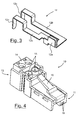
- the adaptor device 10 comprises, at a first end, an interface 11 configured as an RJ-45 type connector from which at least two contacts 12 face out on a first side.
- the at least two contacts 12 each comprise a first portion 12a projecting from the RJ-45 type interface 11, a second portion 12b made as a track and a third portion 12c configured as a pin.
- a third portion 12c of contact 12 can be made, in an equivalent way, as a cylindrical or flat pin.
- the first portions 12a of the at least two contacts 12 respectively face out from the seats 18 for the contacts foreseen in the interface 11 arranged at the seventh and eighth standard position of the contacts of an RJ-45 type connector. In this way it is ensured that, even in case in which the adaptor is used inappropriately, there will be no short circuits that could damage the electronic components.
- a housing seat 13 is foreseen, suitable for receiving a connector 14 for removable type printed circuit.
- the seat 13 is made in such a way as to house different types of printed circuit connectors, like for example, a removable clamp connector 14 illustrated in figure 4 , or else a different type of removable connector like for example an insulation displacement connector.
- the housing seat 13 has a box-shaped configuration open on one side and on top and houses inside of it the third portions 12c of contacts 12 that project towards the open upper face.
- the third portion 12c configured as a pin is preferably made with sizes and diameter equal to that of the male pins mounted on printed circuits for coupling with standard type connectors 14.
- the two contacts are spaced apart by a measurement corresponding to the standard measurement of the pitch of such male pins.
- the standard type printed circuit connectors 14 comprise first seats 15 for coupling with at least two pin-shaped contacts, which then couple with the third portions 12c of the contacts 12 of the adaptor device 10 projecting inside the housing seat 13, and a second seat in which a plurality of conductors (not illustrated) are suitably inserted and held through special locking means.
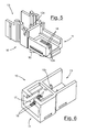
- the interface 11 is of the male RJ-45 type and therefore comprises, on the second side of the interface 11, opposite to where the contacts 12 face out, a flexible tab 16 diverging from the interface 11, suitable for cooperating with the seat of a female RJ-45 connector to keep a fixed but releasable coupling between the two connectors.
- the housing seat 13 for printed circuit connectors faces out from the same side in which the flexible tab 16 is foreseen, thus ensuring a substantially equivalent bulk to that of a conventional male RJ-45 type connector.
- the adaptor devices 10 according to the first two embodiments of the present invention can be connected to a device provided with a female RJ-45 type interface so as to transform such an interface into a generic interface for projecting male or pin connectors of a printed circuit board. It is possible in this way, to use any conductor for the connection of a device with RJ-45 interface to a system using a different interface.
- Figures 6 and 7 show a third embodiment in which the interface 11 is of the female RJ-45 type, therefore comprising a seat 17 suitable for receiving a male RJ-45 connector, inside of which the first portions 12a of the at least two contacts 12 face outwards.
- the first portions 12a of the at least two contacts 12 preferably face out from the seats 18 for the contacts foreseen in the interface 11 respectively arranged at the seventh and eighth standard position of the contacts of an RJ-45 type connector.
- the adaptor device 10 can be used to modify the interface of a conductor having RJ-45 interfaces, so that it can be connected to a different type of interface.
Landscapes
- Details Of Connecting Devices For Male And Female Coupling (AREA)
- Coupling Device And Connection With Printed Circuit (AREA)
Applications Claiming Priority (1)
| Application Number | Priority Date | Filing Date | Title |
|---|---|---|---|
| ITMI20080802 ITMI20080802A1 (it) | 2008-04-30 | 2008-04-30 | Dispositivo adattatore per connettori per circuito stampato |
Publications (2)
| Publication Number | Publication Date |
|---|---|
| EP2113972A2 true EP2113972A2 (de) | 2009-11-04 |
| EP2113972A3 EP2113972A3 (de) | 2011-06-01 |
Family
ID=40297049
Family Applications (1)
| Application Number | Title | Priority Date | Filing Date |
|---|---|---|---|
| EP09157527A Withdrawn EP2113972A3 (de) | 2008-04-30 | 2009-04-07 | Adaptervorrichtung für Leiterplattensteckverbinder |
Country Status (2)
| Country | Link |
|---|---|
| EP (1) | EP2113972A3 (de) |
| IT (1) | ITMI20080802A1 (de) |
Cited By (2)
| Publication number | Priority date | Publication date | Assignee | Title |
|---|---|---|---|---|
| WO2013032454A1 (en) * | 2011-08-31 | 2013-03-07 | Hewlett-Packard Development Company, L.P. | Port with biased guide |
| CN109618491A (zh) * | 2018-12-29 | 2019-04-12 | 联想(北京)有限公司 | 一种电路板 |
Family Cites Families (6)
| Publication number | Priority date | Publication date | Assignee | Title |
|---|---|---|---|---|
| GB2110886B (en) * | 1981-12-01 | 1985-12-11 | Bunker Ramo | Electrical connector member |
| JPH0312231Y2 (de) * | 1986-09-22 | 1991-03-22 | ||
| GB8725475D0 (en) * | 1987-10-30 | 1987-12-02 | Amp Holland | Modular jack |
| TW458433U (en) * | 2000-10-24 | 2001-10-01 | Hon Hai Prec Ind Co Ltd | Cable connector |
| TW472966U (en) * | 2000-12-30 | 2002-01-11 | Hon Hai Prec Ind Co Ltd | Cable connector assembly |
| TWM254780U (en) * | 2003-12-09 | 2005-01-01 | Hon Hai Prec Ind Co Ltd | Electrical connector |
-
2008
- 2008-04-30 IT ITMI20080802 patent/ITMI20080802A1/it unknown
-
2009
- 2009-04-07 EP EP09157527A patent/EP2113972A3/de not_active Withdrawn
Cited By (2)
| Publication number | Priority date | Publication date | Assignee | Title |
|---|---|---|---|---|
| WO2013032454A1 (en) * | 2011-08-31 | 2013-03-07 | Hewlett-Packard Development Company, L.P. | Port with biased guide |
| CN109618491A (zh) * | 2018-12-29 | 2019-04-12 | 联想(北京)有限公司 | 一种电路板 |
Also Published As
| Publication number | Publication date |
|---|---|
| EP2113972A3 (de) | 2011-06-01 |
| ITMI20080802A1 (it) | 2009-11-01 |
Similar Documents
| Publication | Publication Date | Title |
|---|---|---|
| US8888522B2 (en) | Electric plug-in connection system | |
| US7281958B2 (en) | Power terminal block | |
| US6123585A (en) | Module for connecting actuators and/or sensors | |
| JP4440111B2 (ja) | ネットワーク接続センサ組立体 | |
| US6273750B1 (en) | Connector and cable system for panel-mounted circuitry | |
| US5908322A (en) | Joint connector | |
| US10012403B2 (en) | Wiring connector housing | |
| JP3720098B2 (ja) | 電子コントロールシステムおよび自動化システム用のモジュール式制御装置 | |
| RU2470428C1 (ru) | Системный штепсельный соединитель с переходным модулем | |
| US5094626A (en) | Set of assembly elements intended to facilitate concurrent electrical connection of a plurality of modular automatic circuit breakers | |
| US20070161262A1 (en) | Detachable magnetic electrical connector | |
| US20230411888A1 (en) | Electrical connector for a controller | |
| US6921294B2 (en) | Universal wire harness for detectors | |
| EP2346116B1 (de) | Endgerätblock | |
| US6955560B1 (en) | Adapter system for connecting coaxial cable to telephone cable | |
| US20050196998A1 (en) | System for providing data and power signals to networked devices | |
| US6099333A (en) | Customer bridge with automatic connect and disconnect features | |
| CN118947025A (zh) | 用于容纳在金属的插接器模块框架中和用于其接地的接地模块 | |
| US20030036313A1 (en) | Plug connector with adapter | |
| US20080038962A1 (en) | Distribution Module for Converting Between Symmetrical and Asymmetrical Data Transmission Paths | |
| CN206893859U (zh) | 同轴电缆连接器组件 | |
| EP1300912A1 (de) | Elektrische Anschlussdose | |
| JPH0223014A (ja) | 電気通信用接続装置 | |
| US20070298646A1 (en) | Improved connector release tab | |
| CN217158053U (zh) | 继电器底座及继电器 |
Legal Events
| Date | Code | Title | Description |
|---|---|---|---|
| PUAI | Public reference made under article 153(3) epc to a published international application that has entered the european phase |
Free format text: ORIGINAL CODE: 0009012 |
|
| AK | Designated contracting states |
Kind code of ref document: A2 Designated state(s): AT BE BG CH CY CZ DE DK EE ES FI FR GB GR HR HU IE IS IT LI LT LU LV MC MK MT NL NO PL PT RO SE SI SK TR |
|
| PUAL | Search report despatched |
Free format text: ORIGINAL CODE: 0009013 |
|
| AK | Designated contracting states |
Kind code of ref document: A3 Designated state(s): AT BE BG CH CY CZ DE DK EE ES FI FR GB GR HR HU IE IS IT LI LT LU LV MC MK MT NL NO PL PT RO SE SI SK TR |
|
| 17P | Request for examination filed |
Effective date: 20111123 |
|
| GRAP | Despatch of communication of intention to grant a patent |
Free format text: ORIGINAL CODE: EPIDOSNIGR1 |
|
| RIC1 | Information provided on ipc code assigned before grant |
Ipc: H01R 24/00 20110101AFI20140424BHEP |
|
| INTG | Intention to grant announced |
Effective date: 20140521 |
|
| STAA | Information on the status of an ep patent application or granted ep patent |
Free format text: STATUS: THE APPLICATION IS DEEMED TO BE WITHDRAWN |
|
| 18D | Application deemed to be withdrawn |
Effective date: 20141001 |