EP2113993B1 - Permanentmagnet-synchronmotor und abgeschlossener kompressor - Google Patents
Permanentmagnet-synchronmotor und abgeschlossener kompressor Download PDFInfo
- Publication number
- EP2113993B1 EP2113993B1 EP07714641.3A EP07714641A EP2113993B1 EP 2113993 B1 EP2113993 B1 EP 2113993B1 EP 07714641 A EP07714641 A EP 07714641A EP 2113993 B1 EP2113993 B1 EP 2113993B1
- Authority
- EP
- European Patent Office
- Prior art keywords
- permanent magnet
- slits
- rotor core
- rotor
- synchronous motor
- Prior art date
- Legal status (The legal status is an assumption and is not a legal conclusion. Google has not performed a legal analysis and makes no representation as to the accuracy of the status listed.)
- Not-in-force
Links
Images

Classifications
-
- H—ELECTRICITY
- H02—GENERATION; CONVERSION OR DISTRIBUTION OF ELECTRIC POWER
- H02K—DYNAMO-ELECTRIC MACHINES
- H02K1/00—Details of the magnetic circuit
- H02K1/06—Details of the magnetic circuit characterised by the shape, form or construction
- H02K1/22—Rotating parts of the magnetic circuit
-
- H—ELECTRICITY
- H02—GENERATION; CONVERSION OR DISTRIBUTION OF ELECTRIC POWER
- H02K—DYNAMO-ELECTRIC MACHINES
- H02K1/00—Details of the magnetic circuit
- H02K1/06—Details of the magnetic circuit characterised by the shape, form or construction
- H02K1/22—Rotating parts of the magnetic circuit
- H02K1/27—Rotor cores with permanent magnets
- H02K1/2706—Inner rotors
- H02K1/272—Inner rotors the magnetisation axis of the magnets being perpendicular to the rotor axis
- H02K1/274—Inner rotors the magnetisation axis of the magnets being perpendicular to the rotor axis the rotor consisting of two or more circumferentially positioned magnets
- H02K1/2753—Inner rotors the magnetisation axis of the magnets being perpendicular to the rotor axis the rotor consisting of two or more circumferentially positioned magnets the rotor consisting of magnets or groups of magnets arranged with alternating polarity
- H02K1/276—Magnets embedded in the magnetic core, e.g. interior permanent magnets [IPM]
-
- H—ELECTRICITY
- H02—GENERATION; CONVERSION OR DISTRIBUTION OF ELECTRIC POWER
- H02K—DYNAMO-ELECTRIC MACHINES
- H02K1/00—Details of the magnetic circuit
- H02K1/06—Details of the magnetic circuit characterised by the shape, form or construction
- H02K1/22—Rotating parts of the magnetic circuit
- H02K1/27—Rotor cores with permanent magnets
-
- H—ELECTRICITY
- H02—GENERATION; CONVERSION OR DISTRIBUTION OF ELECTRIC POWER
- H02K—DYNAMO-ELECTRIC MACHINES
- H02K2213/00—Specific aspects, not otherwise provided for and not covered by codes H02K2201/00 - H02K2211/00
- H02K2213/03—Machines characterised by numerical values, ranges, mathematical expressions or similar information
-
- H—ELECTRICITY
- H02—GENERATION; CONVERSION OR DISTRIBUTION OF ELECTRIC POWER
- H02K—DYNAMO-ELECTRIC MACHINES
- H02K29/00—Motors or generators having non-mechanical commutating devices, e.g. discharge tubes or semiconductor devices
- H02K29/03—Motors or generators having non-mechanical commutating devices, e.g. discharge tubes or semiconductor devices with a magnetic circuit specially adapted for avoiding torque ripples or self-starting problems
Definitions
- the present invention relates to a permanent magnet synchronous motor, which is generally mounted on a hermetic compressor, etc.
- a rotor with embedded permanent magnets has been proposed to reduce torque ripple in a rotor with embedded permanent magnets where the phase of a current is difficult to control (See Patent Document 1, for example).
- the rotor with embedded permanent magnets has permanent magnets embedded in an approximately cylindrical rotor core in a longitudinal direction.
- the rotor with embedded permanent magnets has a plurality of slits elongated from a vicinity of each permanent magnet on the outer circumferential side of the rotor core to a vicinity of the outer surface of the rotor.
- a permanent magnet motor has also been proposed in pursuit of achieving a highly efficient permanent magnet motor with low noise and low vibration.
- the permanent magnet motor is designed to reduce armature reaction flux and also improve magnetic flux distribution of a core at an outer circumference (See Patent Document 2, for example).
- the permanent magnet motor is characterized by including permanent magnet holding slots, which are formed in a rotor core in portions corresponding to the respective sides of an approximately regular polygon whose center is at the axial center of the rotor core; permanent magnets embedded in the respective permanent magnetic holding slots; and four or more radially elongated slits, which are formed in the core on the outer circumferential side of the permanent magnet holding slots, and are spaced from each other along each of the permanent magnet holding slots.
- the permanent magnet motor is also characterized in that the pitches of the slits in end portions (near the outer circumference of the rotor core) in the radial direction are made approximately equal, and the pitches of the slits in inner portions in the radial direction are made varied so that a pitch in a portion near the permanent magnet center is the largest, and pitches then decrease with distance from the center to the ends.
- Electromotive force in the stator windings contains a waveform with a large amount of harmonic components. This may cause an increase in vibration and noise. In addition, an increased iron loss may result in inefficiency.
- the permanent magnet motor of the Patent Document 2 also poses the following problems. While the amount of harmonic components contained in electromotive force in the stator windings is lowered, the complicated shape of the slits increases the process costs. In addition, the permanent magnet motor fails to achieve the effective use of the magnetic flux of the permanent magnets in their end portions. This may also result in inefficiency.
- JP 2005 245148 A discloses a hermetic compressor with a permanent magnet synchronous motor, where the stator is formed by layers of magnetic steel plates.
- the present invention is directed to solving problems mentioned earlier. It is an object to provide a permanent magnet synchronous motor and a hermetic compressor that are highly efficient with low vibration and low noise.
- a permanent magnet synchronous motor according to this invention which includes a stator and a rotor, is characterized as follows.
- the stator includes a stator core and stator windings.
- the stator core is formed by layers of magnetic steel plates and include magnetic pole teeth which are each formed between adjacent slots.
- the stator windings are provided in the slots of the stator core.
- the rotor is placed on an inner circumferential side of the magnetic pole teeth of the stator via an air gap.
- the rotor includes a rotor core that is formed by layers of magnetic steel plates; a plurality of magnet retaining holes formed in the rotor core along an outer circumference of the rotor core; permanent magnets inserted in the magnet retaining holes; and a plurality of slits formed in the rotor core on an outer circumferential side of the magnet retaining holes.
- the slits are elongated from a vicinity of the permanent magnets to a vicinity of the outer circumference of the rotor core,
- slits in a vicinity of a magnetic pole center of the rotor core are oriented in a direction toward a point in a line of the magnetic pole center by a permanent magnet converges outside the rotor core, whereas slits in a vicinity of a pole border portion of the rotor core are oriented in another direction that is different from the direction of the slits formed in the vicinity of the magnetic pole center of the rotor core.
- the permanent magnet synchronous motor is further characterized in that the stator may use a concentrated winding method by which the stator windings are directly wound around the magnetic pole tooth.
- the permanent magnet synchronous motor is further characterized in that the slits in the vicinity of the magnetic pole center of the rotor core may be formed within a width of the magnetic pole tooth on a side facing the air gap and opposed to the rotor core.
- stator core may be an assembly of separate cores, each of which may include one of the magnetic pole teeth.
- the permanent magnet synchronous motor is further characterized in that a distance between the slits that are formed in the vicinity of pole border portions of the rotor core and positioned at both ends of a magnet retaining hole in the circumferential direction may be larger than a width of the magnetic pole tooth on a side facing the air gap. The distance may be measured from corners of the slits on a side facing a magnet retaining hole and on sides facing respective pole border portions of the rotor core.
- the permanent magnet synchronous motor is further characterized in that a width in a radial direction of an outside narrow bridge in the pole border portion may be larger than a width in the radial direction of another outside narrow bridge.
- the outside narrow bridge in the pole border portion may be a part of the core on the outer circumferential side of a magnet retaining hole in a vicinity of the pole border portion of rotor, and the another outside narrow bridge may be a part of the core on the outer circumferential side of one of the slits formed in the vicinity of the pole border portion.
- the permanent magnet synchronous motor is further characterized in that a sum of the width in the radial direction of the another outside narrow bridge and a width in the radial direction of an inside narrow bridge may be larger than the width in the radial direction of the outside narrow bridge in the pole border portion.
- the inside narrow bridge may be a part of the core between the one of the slits formed in the vicinity of the pole border portion and the magnet regaining hole.
- a hermetic compressor according to this invention is characterized by including the permanent magnet synchronous motor mentioned above.
- a permanent magnet synchronous motor according to the present invention may achieve an effective use of the magnetic flux of permanent magnets. This may result in achieving a highly efficient permanent magnet synchronous motor.
- the highly efficient permanent magnet synchronous motor may further achieve low vibration and low noise by controlling the levels of vibration and noise generated by a motor.
- Fig. 1 through Fig. 3 describe a first embodiment.
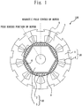
- Fig. 1 shows a horizontal cross section of a permanent magnet synchronous motor 100.
- Fig. 2 shows a diagram illustrating a part of a rotor 40 of the permanent magnet synchronous motor 100.
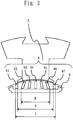
- Fig. 3 shows a diagram illustrating a part of a stator 30 and a part of the rotor 40 of the permanent magnet synchronous motor 100.
- the permanent magnet synchronous motor 100 includes the stator 30 and the rotor 40.
- the stator 30 includes a stator core 1 and stator windings 4.
- the stator core 1 is formed to include nine axially extending slots 3 along the inner circumference of the stator 30.
- the stator core 1 is formed by layers of magnetic steel plates, each being approximately 0.1 to 1.0 mm thick.
- Nine magnetic pole teeth 2 are formed each between adjacent slots 3.
- Each magnetic pole tooth 2 protrudes from the side of the outer circumference to the side of the inner circumference in a shape that opposite sides are almost parallel.
- the magnetic pole tooth is formed like a circular arc spreading out along the circumferential direction on both sides of the inner circumference and the outer circumference.
- the stator core 1 is an assembly of nine separate parts, each corresponding to a single magnetic pole tooth 2.
- the stator windings 4 are wound by using a concentrated winding method, thereby winding the windings directly around the separate magnetic pole teeth 2 with a predetermined number of turns.
- the stator windings 4 may be made up of copper or aluminum wires, for example.
- the number of turns of wire, the diameter of a copper wire, etc of the stator windings 4 may be determined according to requirements for the permanent magnet synchronous motor 100 about desired torque, desired number of rotations, desired voltage to be applied to a motor, desired size of the cross-section area of the slot 3, and the like.
- the separate magnetic pole teeth 2 are processed by welding, press fitting, etc. This may result in completion of the stator 30 whose cross section is circular. In the process of press fitting, the separate magnetic pole teeth 2 need to be formed into a corrugated shape at connections to each other.
- the rotor 40 On the inner circumference side of the stator 30 is the rotor 40 placed via an air gap of approximately 0.1 to 2.0 mm.
- the rotor 40 includes a rotor core 5 and permanent magnets 7.
- the rotor core 5, like the stator core 1, is formed by layers of magnetic steel plates, each being approximately 0.1 to 1.0 mm thick.
- the rotor core 5 includes six magnet retaining holes 8 situated at positions corresponding to the respective sides of an approximate regular hexagon that centers on the center of the axis of the rotor core 5.
- Six pieces of the permanent magnets 7 are embedded in the magnet retaining holes 8 in such a manner that magnetic North Poles and magnetic South Poles are arranged alternately along the circumferential direction.
- the permanent magnets 7 are flat rate-earth magnets, which may consist primarily of neodymium, iron, and boron.
- Fig. 1 shows an example of seven slits 6 provided for each pole of the permanent magnets 7 (one of the magnet retaining holes 8).
- the center of the magnet retaining hole 8 (the permanent magnet 7) is defined as a "magnetic pole center of rotor”.
- a border portion between adjacent magnet retaining holes 8 (the permanent magnets 7) is defined as a "pole border portion of rotor”.
- Fig. 2 shows a portion of the rotor 40 of the permanent magnet synchronous motor 100 for one pole. Referring to Fig. 2 , seven slits 6, slits 61-67, are provided for one pole where a slit 64 is positioned on the magnetic pole center of rotor.
- the seven slits 61-67 are positioned symmetrically with respect to the magnetic pole center of rotor with the slit 64 on the magnetic pole center of rotor.
- the seven slits 61-67 are spaced from each other in this order from one end of the magnet retaining hole 8.
- the slits 62-66 five slits out of the seven slits, positioned at or near the magnetic pole center of rotor, are oriented in the direction where the magnetic flux generated by the permanent magnet 7 almost converges outside the rotor 40 so that the magnetic flux converges at the magnetic pole center of rotor. It is preferable that the center lines of the five slits 62-66 converge at a point X outside the rotor 40 as shown in Fig. 2 . Equivalent properties, however, may be obtained even when these center lines almost converge at the point X as well.
- the point X is preferable to locate inside the outer circumference of the stator core 1.
- the slits 61 and 67 two slits placed in the vicinity of pole border portions, are oriented in a different direction from the direction of the other five slits, 62-66, placed at or near the magnetic pole center of rotor.
- the two slits, 61 and 67, in the vicinity of the pole border portions may be oriented in a perpendicular direction with respect to the permanent magnet 7 (the magnet retaining hole 8), for example.
- the stator core 1 has nine magnetic poles (slots) whereas the rotor has six poles. For this reason, the width of the permanent magnet 7 is made larger than the magnetic pole width of the magnetic pole tooth 2 of the stator 30. However, the five slits 62-66 positioned at or near the magnetic pole center of rotor are oriented in the direction where the magnetic flux generated by the permanent magnet 7 almost converges outside the rotor 40. This allows the stator 30 based on the concentrated winding method to make effective use of the magnetic flux of the permanent magnets 7.
- the slits 61 and 67, positioned in the vicinity of the pole border portions, are oriented perpendicular to the permanent magnet 7.
- the slits 61 and 67, in the vicinity of the pole border portions may be oriented in the direction where the magnetic flux converges, in the same manner as that of the slits 62-66 positioned at or near the magnetic pole center of rotor. This may also help achieve effective use of the magnet flux. In this case, however, the inclination of the slit 61, 67 from the orientation of the magnetic flux of the permanent magnet 7 becomes large. This may cause blocking of the magnetic flux of the permanent magnet 7 at the ends in the pole border portions of rotor.
- the slits 61 and 67 positioned in the vicinity of the pole border portions of rotor, may be oriented in the different direction from the direction of the orientation of the other slits 62-66 positioned at or near the magnetic pole center of rotor (e.g., the slits 61 and 67 may be oriented perpendicular to the permanent magnet 7). This may help achieve effective use of the magnetic flux of the permanent magnets 7 not only in the center portion but also on the edges.
- the effective use of the magnetic flux of the permanent magnet 7 may achieve as follows: when the amount of electric current applied to the stator windings 4 is constant, then torque generated by the permanent magnet synchronous motor 100 may become large; and when the torque is constant, then the electric current applied to the stator windings 4 may become small in amount. This may reduce copper loss and result in providing the permanent magnet synchronous motor 100 that is highly efficient.
- the volume of the permanent magnet 7 may become small. This may result in providing the permanent magnet synchronous motor 100 at low costs.
- Fig. 3 shows a cross section of a permanent magnet synchronous motor illustrating a part of the stator core 1 only for one of the nine magnetic pole teeth 2 and a part of the rotor core 5 only for one of the six poles.
- an A denotes the size of the width of the magnetic pole tooth 2 on the side of the air gap facing the rotor core 5.
- a B denotes a distance between the slit 62 and the slits 66.
- the slits 62 and 66 are the farthest from the magnetic pole center of rotor of the six slits 62-66 oriented in the direction where the magnetic flux converges. (The measurement of the distance will be taken from the corners of the slits 62 and 66 on the side of the respective pole border portions of rotor.)
- the slits are formed to satisfy A>B.
- a C denotes a distance between the slit 61 and the slit 67 positioned in the vicinity of the respective pole border portions of rotor. The distance is actually between the corners of the slits 61 and 67 facing the magnet retaining hole 8 and the respective pole border portions of rotor.
- electrotive force the waveform of voltage induced to the stator windings 4
- the waveform of the electromotive force is almost determined by the shapes and positions of the stator core 1, the permanent magnets 7, the magnet retaining holes 8 and the slits 6.
- the shapes of the slits 61 and 67 in the vicinity of the respective pole border portions of rotor especially have a great influence on the waveform of the electromotive force.
- the waveform of the electromotive force approximates a sine wave, that is, the harmonic components of the electromotive force is reduced, then the levels of vibration and noise caused by the permanent magnet synchronous motor 100 in operation may be controlled.
- Another advantage is to prevent deterioration in efficiency caused by an increase in iron loss.
- C>A then the magnetic flux in the pole border portions of rotor may have a smooth change. This may serve to make the waveform of the electromotive force approximate a sine wave.
- the permanent magnet synchronous motor 100 may achieve low vibration and low noise.
- the size of C is made smaller than the horizontal width of the permanent magnet 7, then an enhanced effect may be obtained.
- the stator 30 has nine pieces of the magnetic pole teeth 2 and the rotor 40 has six magnetic poles, as described. A similar effect may also be obtained, however, with another combination of the stator 30 having 12 pieces of the magnetic pole teeth 2 and the rotor 40 having eight magnetic poles, for example. Even a combination of the stator 30 having 18 pieces of the magnetic pole teeth 2 and the rotor 40 having 12 magnetic poles may achieve a similar effect.
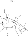
- Fig. 4 shows a diagram describing a second embodiment, which illustrates a portion of the rotor core 5 of the permanent magnet synchronous motor 100.
- an outside narrow bridge 9 denotes a part of the core on the outer circumferential side of the slit 67 in the vicinity of the pole border portion.
- An inside narrow bridge 11 denotes a part of the core between the slit 67 and the magnet retaining hole 8.
- An outside narrow bridge in pole border portion 10 denotes a part of the core adjacent to the magnet retaining hole 8 in the vicinity of the pole border portion on the outer circumferential side.
- D1 ⁇ D2 may be satisfied where the D1 denotes the size of the width (a size in the radial direction) of the outside narrow bridge 9 and the D2 denotes the size of the width (a size in the radial direction) of the outside narrow bridge in a pole border portion 10.
- the shape of the slit 67 in the vicinity of the pole border portion of rotor may be a key factor, as described.
- the shape and size of the outside narrow bridge in a pole border portion 10, like the shape of the slit 67, are also key factors for making the waveform of the electromotive force approximate a sine wave.
- the electromotive force becomes large in value. There is a tendency, however, the waveform of the electromotive force includes distortion with harmonic components. The waveform of the electromotive force may be able to approximate a sine wave when D2>D1.
- the size of the D2 is too large, however, the magnetic flux of the permanent magnet 7 may leak to the outside narrow bridge in pole border portion 10 of an adjacent pole. This may result in reducing the voltage value of the electromotive force, and thereby deteriorate the efficiency of the permanent magnet synchronous motor. It is preferable therefore to set the size of the D2 approximately to 1.2 to 3 times the size of D1. It is also desirable to set the size of D1 approximately to 1 to 2 times the thickness (approximately 0.1 to 1 mm) of one of the magnetic steel plates that form the rotor core 5.
- the permanent magnet synchronous motor 100 runs at high speed of over 7000 revolutions per minute (rpm)
- the following may occur: if the size of the D2 is too small for such a high speed operation, the stress may be concentrated at the outside narrow bridge in pole border portion 10 due to centrifugal forces at high speed rotation; and then in the worst case, the outside narrow bridge in pole border portion 10 may brake or may be damaged.
- the strength may be increased against centrifugal forces. Therefore, the permanent magnet synchronous motor 100 may achieve high reliability. Another advantage is to achieve the permanent magnet synchronous motor 100 with low vibration and low noise due to reduced harmonic components in the electromotive force.
- a D3 denotes the size of the width of the inside narrow bridge 11, in which D2 ⁇ D1+D3 is satisfied.
- the magnetic flux of the permanent magnet 7 includes a portion that flows to the magnetic pole tooth 2 of the stator 30 to be used as torque and a portion of leakage flux that flows in the direction of adjacent permanent magnets 7.
- the leakage flux passes through the outside narrow bridge in a pole border portion 10, and thus the size of the D2 is very important.
- the magnetic flux of the permanent magnet 7 in a portion nearer to the magnetic pole center of rotor than the slit 67 passes through the outside narrow bridge 9 (the width size D1) and the inside narrow bridge 11 (the width size D3), and then leaks to the adjacent permanent magnet 7 via the outside narrow bridge in pole border portion 10 (the width size D2).
- the leakage flux of the permanent magnet 7 through the D1 and the D3 may be controlled at the D2. This may help achieve effective use of the magnetic flux of the permanent magnet 7. As a result, the permanent magnet synchronous motor 100 may achieve high efficiency.
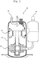
- Fig. 5 shows a diagram describing a third embodiment, which illustrates a vertical cross section of a rotary compressor 20 (an example of a hermetic compressor).
- a hermetic housing 22 of the rotary compressor 20 contains a motor unit 21 and a compressor unit 23.
- the motor unit 21 the permanent magnet synchronous motor 100 described in the first embodiment or the second embodiment may be used.
- a suction tube 24 is connected to an evaporator of a refrigeration cycle (not shown in the figure) for leading a refrigerant to the compressor unit 23.
- a discharge tube 25 is connected to a condenser of the refrigeration cycle for sending high pressure refrigerant from the hermetic container 22 to the refrigeration cycle.
- the rotary compressor 20 When the permanent magnet synchronous motor 100 described in the first embodiment or the second embodiment is mounted in the rotary compressor 20, the rotary compressor 20 then becomes highly efficient because the permanent magnet synchronous motor 100 is highly efficient.
- This highly efficient rotary compressor 20 may be used in an air conditioner or a fridge-freezer. This may greatly contribute to the purposes of energy conservation.
Landscapes
- Engineering & Computer Science (AREA)
- Power Engineering (AREA)
- Permanent Field Magnets Of Synchronous Machinery (AREA)
- Iron Core Of Rotating Electric Machines (AREA)
- Permanent Magnet Type Synchronous Machine (AREA)
Claims (8)
- Permanentmagnet-Synchronmotor (100), umfassend:einen Stator (30); undeinen Rotor (40),wobei der Stator enthält:einen Statorkern (1), der durch Lagen aus magnetischen Stahlplatten gebildet ist, wobei der Statorkern Magnetpafzähne (2) enthält, wobei jeder Magnetpolzahn zwischen benachbarten Schlitzen (3) ausgebildet ist; undStatorwicklungen (4), die in den Schlitzen des Statorkerns angeordnet sind,wobei der Rotor, welcher auf einer inneren Umfangsseite der Magnetpolzähne des Stators über einen Luftspalt angeordnet ist, enthält:einen Rotorkern (5), der durch Lagen aus magnetischen Stahlplatten gebildet ist;eine Vielzahl von Magnethaltelöchern (8), die in dem Rotorkern entlang eines äußeren Umfangs des Rotorkerns ausgebildet sind;Permanentmagneten (7), die in die Magnethaltelöcher eingesetzt sind; undeine Vielzahl von Schlitzen (6, 61-67), die im Rotorkern auf einer äußeren Umfangsseite der Magnethaltelöcher ausgebildet sind, wobei die Vielzahl von Schlitzen von einer Nähe zu den Permanentmagneten zu einer Nähe zum äußeren Umfang des Rotorkerns sich erstrecken,dadurch gekennzeichnet, dassaus der Vielzahl von Schlitzen fünf oder mehr Schlitze (62-66), die in einer Nähe einer Magnetpolmitte des Rotorkerns ausgebildet sind, in eine Richtung zu einem Punkt in einer Linie der Magnetpolmitte außerhalb des Rotorkerns orientiert sind, und in einer Nähe eines Polrandbereiches des Rotorkerns ausgebildete Schlitze (61, 67) in eine anderen Richtung orientiert sind, die sich von der Richtung der in der Umgebung des Magnetpolmitte des Rotorkerns ausgebildeten Schlitze (62-66) unterscheidet.
- Permanentmagnet-Synchronmotor nach Anspruch 1, wobei der Stator (30) ein konzentriertes Wicklungsverfahren verwendet, durch welches die Statorwicklungen (4) direkt um den Magnetpolzahn (2) gewickelt werden.
- Permanentmagnet-Synchronmotor nach Anspruch 2, wobei die Schlitze (62-66) in der Nähe der Magnetpolmitte des Rotorkerns (5) innerhalb einer auf einer dem Luftspalt zugewandten Seite befindlichen und dem Rotorkern (5) gegenüberliegenden Breite des Magnetpolzahns (2) ausgebildet sind.
- Permanentmagnet-Synchronmotor nach Anspruch 2, wobei der Statorkern (1) eine Anordnung aus separaten Kernen ist, wobei jeder Kern einen der Magnetpolzähne (2) enthält.
- Permanentmagnet-Synchronmotor nach Anspruch 2, wobei ein Abstand (C) zwischen den Schlitzen (61, 67), die in der Nähe von Polrandbereichen des Rotorkerns (5) ausgebildet und an in der Umfangsrichtung beiden Enden eines Magnethaltelochs (8) positioniert sind, größer ist als eine Breite des Magnetpolzahns (2) auf einer dem Luftspalt zugewandten Seite, wobei der Abstand (C) von Ecken der Schlitze (61, 57) auf einer einem Magnethalteloch (8) zugewandten Seite und auf den entsprechenden Polrandbereichen des Rotorkerns zugewandten Seiten gemessen wird.
- Permanentmagnet-Synchronmotor nach Anspruch 1, wobei eine Breite (D2) in einer radialen Richtung eines äußeren schmalen Stegs (10) im Polrandbereich größer ist als eine Breite (D1) in der radialen Richtung eines anderen äußeren schmalen Stegs (9), wobei der äußere schmale Steg (10) im Polrandbereich ein Teil des Rotorkerns (5) auf der äußerer Umfangsseite eines Magnethaltelochs (8) in einer Nähe des Polrandbereich des Rotors ist, und der andere äußere schmale Steg (9) ein Teil des Rotorkerns (5) auf der äußerer Umfangsseite von einem der in der Nähe des Polrandbereich ausgebildeten Schlitze (62-66) ist.
- Permanentmagnet-Synchronmotor nach Anspruch 6, wobei eine Summe der Breite (D1) in der radialen Richtung des anderen äußeren schmalen Stegs (9) und einer Breite (D3) in der radialen Richtung eines inneren schmalen Stegs (11) größer ist als die Breite (D2) in der radialen Richtung des äußeren schmalen Stegs (10) im Polrandbereich, wobei der innere schmale Steg (11) ein Teil des Rotorkerns (5) zwischen dem einen der Schlitze (61, 67), die in der Nähe des Polrandbereiches ausgebildet sind, und einem Magnethalteloch ist.
- Hermetischer Verdichter (20), umfassend den Permanentmagnet-Synchronmotor nach einem der Ansprüche 1, 6 und 7.
Priority Applications (1)
| Application Number | Priority Date | Filing Date | Title |
|---|---|---|---|
| EP14161689.6A EP2750264B1 (de) | 2007-02-21 | 2007-02-21 | Permanentmagnetsynchronmotor und hermetischer Kompressor |
Applications Claiming Priority (1)
| Application Number | Priority Date | Filing Date | Title |
|---|---|---|---|
| PCT/JP2007/053141 WO2008102439A1 (ja) | 2007-02-21 | 2007-02-21 | 永久磁石同期電動機及び密閉型圧縮機 |
Related Child Applications (2)
| Application Number | Title | Priority Date | Filing Date |
|---|---|---|---|
| EP14161689.6A Division EP2750264B1 (de) | 2007-02-21 | 2007-02-21 | Permanentmagnetsynchronmotor und hermetischer Kompressor |
| EP14161689.6A Division-Into EP2750264B1 (de) | 2007-02-21 | 2007-02-21 | Permanentmagnetsynchronmotor und hermetischer Kompressor |
Publications (3)
| Publication Number | Publication Date |
|---|---|
| EP2113993A1 EP2113993A1 (de) | 2009-11-04 |
| EP2113993A4 EP2113993A4 (de) | 2013-03-20 |
| EP2113993B1 true EP2113993B1 (de) | 2017-12-20 |
Family
ID=39709725
Family Applications (2)
| Application Number | Title | Priority Date | Filing Date |
|---|---|---|---|
| EP07714641.3A Not-in-force EP2113993B1 (de) | 2007-02-21 | 2007-02-21 | Permanentmagnet-synchronmotor und abgeschlossener kompressor |
| EP14161689.6A Not-in-force EP2750264B1 (de) | 2007-02-21 | 2007-02-21 | Permanentmagnetsynchronmotor und hermetischer Kompressor |
Family Applications After (1)
| Application Number | Title | Priority Date | Filing Date |
|---|---|---|---|
| EP14161689.6A Not-in-force EP2750264B1 (de) | 2007-02-21 | 2007-02-21 | Permanentmagnetsynchronmotor und hermetischer Kompressor |
Country Status (7)
| Country | Link |
|---|---|
| US (1) | US8106557B2 (de) |
| EP (2) | EP2113993B1 (de) |
| JP (1) | JP4838347B2 (de) |
| KR (2) | KR101065991B1 (de) |
| CN (1) | CN101536293B (de) |
| ES (2) | ES2634648T3 (de) |
| WO (1) | WO2008102439A1 (de) |
Families Citing this family (50)
| Publication number | Priority date | Publication date | Assignee | Title |
|---|---|---|---|---|
| KR20030000454A (ko) * | 2001-06-25 | 2003-01-06 | 현대자동차주식회사 | 엔진냉각 방청제 조성물 |
| US8390167B2 (en) * | 2007-11-22 | 2013-03-05 | Lg Electronics Inc. | Motor for compressor and hermetic compressor having the same |
| US8441165B2 (en) * | 2007-11-22 | 2013-05-14 | Lg Electronics Inc. | Motor for compressor and hermetic compressor having the same |
| WO2009066875A2 (en) * | 2007-11-22 | 2009-05-28 | Lg Electronics Inc. | Motor for compressor and hermetic compressor having the same |
| CN201204529Y (zh) * | 2008-08-28 | 2009-03-04 | 无锡东元电机有限公司 | 永磁同步电机 |
| CN102171909B (zh) * | 2008-11-19 | 2013-08-28 | 三菱电机株式会社 | 电动机的转子及电动机、送风机、压缩机 |
| JP5334295B2 (ja) * | 2008-12-25 | 2013-11-06 | 東芝キヤリア株式会社 | 永久磁石電動機及び密閉型圧縮機 |
| JP5334303B2 (ja) * | 2009-02-25 | 2013-11-06 | 東芝キヤリア株式会社 | 永久磁石電動機、密閉型圧縮機、および冷凍サイクル装置 |
| JP5401204B2 (ja) * | 2009-08-07 | 2014-01-29 | 日立アプライアンス株式会社 | 自己始動型永久磁石同期電動機、及び、これを用いた圧縮機と冷凍サイクル |
| JP4964291B2 (ja) * | 2009-12-01 | 2012-06-27 | 三菱電機株式会社 | 永久磁石埋込型モータの回転子及び送風機及び圧縮機 |
| EP2536003B1 (de) * | 2010-02-08 | 2018-01-17 | Mitsubishi Electric Corporation | Motor,- lüfter- und kompressorrotor mit eingebettetem permanentmagnetmotor |
| CN102444580B (zh) * | 2010-09-30 | 2016-03-23 | 艾默生电气公司 | 带有直接起动无刷永磁电动机的数字压缩机 |
| JP5279794B2 (ja) * | 2010-10-28 | 2013-09-04 | 三菱電機株式会社 | 永久磁石埋込型電動機及び密閉型圧縮機 |
| JP5478461B2 (ja) * | 2010-11-09 | 2014-04-23 | 三菱電機株式会社 | 電動機及び圧縮機 |
| JP5811566B2 (ja) * | 2011-03-31 | 2015-11-11 | 株式会社富士通ゼネラル | 回転子および永久磁石電動機 |
| JP5310790B2 (ja) * | 2011-06-10 | 2013-10-09 | 株式会社デンソー | 回転電機のロータ |
| CN103891102B (zh) * | 2011-10-24 | 2016-08-24 | 三菱电机株式会社 | 永久磁铁嵌入式电动机的转子、压缩机和制冷空调装置 |
| CN103138442B (zh) * | 2011-11-25 | 2016-04-13 | 丹佛斯(天津)有限公司 | 内置式永磁电机的转子和使用其的内置式永磁电机 |
| EP2602912A2 (de) * | 2011-12-05 | 2013-06-12 | Samsung Electronics Co., Ltd | Bürstenloser Motor |
| JP5876147B2 (ja) * | 2012-05-28 | 2016-03-02 | 株式会社日立産機システム | 複合トルク型回転電機 |
| JP2014068495A (ja) | 2012-09-27 | 2014-04-17 | Hitachi Automotive Systems Ltd | 回転電機およびそれを用いた電動パワーステアリング装置 |
| WO2014068655A1 (ja) * | 2012-10-30 | 2014-05-08 | 三菱電機株式会社 | 永久磁石埋込型電動機及びそれを備えた冷凍空調装置 |
| KR20140056848A (ko) * | 2012-11-01 | 2014-05-12 | 엘지전자 주식회사 | 로터, 이를 포함하는 모터 및/또는 전기자동차 구동장치 |
| EP2966755B1 (de) * | 2013-03-08 | 2020-04-22 | Mitsubishi Electric Corporation | Wechselstrommotor mit mehreren wicklungen und mehreren phasen sowie stromlenkvorrichtung |
| JP6210711B2 (ja) * | 2013-04-23 | 2017-10-11 | 株式会社日立産機システム | 永久磁石電動機 |
| JP6002625B2 (ja) * | 2013-04-26 | 2016-10-05 | 株式会社日立産機システム | 永久磁石同期機およびこれを用いた圧縮機 |
| WO2015045027A1 (ja) * | 2013-09-25 | 2015-04-02 | 三菱電機株式会社 | 永久磁石埋込型電動機、圧縮機及び冷凍空調装置 |
| WO2015045026A1 (ja) * | 2013-09-25 | 2015-04-02 | 三菱電機株式会社 | 永久磁石埋込型電動機、圧縮機及び冷凍空調装置 |
| WO2015045069A1 (ja) * | 2013-09-26 | 2015-04-02 | 三菱電機株式会社 | 永久磁石埋込型電動機、圧縮機及び冷凍空調装置 |
| CN103532332A (zh) * | 2013-10-30 | 2014-01-22 | 浙江亿利达风机股份有限公司 | 超静音永磁无刷直流电动机 |
| TWI508414B (zh) * | 2013-11-12 | 2015-11-11 | Hon Hai Prec Ind Co Ltd | 轉子及採用該轉子之馬達 |
| WO2015162713A1 (ja) * | 2014-04-23 | 2015-10-29 | 三菱電機株式会社 | 永久磁石埋込型電動機、圧縮機、冷凍空調装置 |
| JP6351734B2 (ja) * | 2014-08-25 | 2018-07-04 | 三菱電機株式会社 | 電動機及び圧縮機及び冷凍サイクル装置 |
| WO2016039746A1 (en) * | 2014-09-11 | 2016-03-17 | Nissan Motor Co., Ltd. | Permanent magnet synchronous motor |
| WO2016056065A1 (ja) * | 2014-10-07 | 2016-04-14 | 三菱電機株式会社 | 永久磁石埋込型電動機、圧縮機、および冷凍空調機 |
| CN104811003B (zh) * | 2015-05-06 | 2017-06-09 | 上海电机学院 | 一种降低内置式永磁电机磁钢涡流损耗的电机结构 |
| GB201510273D0 (en) * | 2015-06-12 | 2015-07-29 | Jaguar Land Rover Ltd | Electric drive motor |
| JP6486492B2 (ja) * | 2015-10-27 | 2019-03-20 | 三菱電機株式会社 | ロータ、永久磁石埋込型電動機および圧縮機 |
| KR102008114B1 (ko) * | 2015-11-18 | 2019-08-06 | 미쓰비시덴키 가부시키가이샤 | 전동기 및 공기 조화기 |
| WO2017138142A1 (ja) * | 2016-02-12 | 2017-08-17 | 三菱電機株式会社 | 電動機、圧縮機及び冷凍空調装置 |
| US10516322B2 (en) * | 2016-05-19 | 2019-12-24 | Arm Ltd. | Method and apparatus for maintenance of electric motor |
| KR20180009189A (ko) * | 2016-07-18 | 2018-01-26 | 하이젠모터 주식회사 | 영구자석 전동기 회전자 |
| CN106300738A (zh) * | 2016-10-20 | 2017-01-04 | 上海日立电器有限公司 | 一种电机转子结构 |
| CN107240975B (zh) * | 2017-08-09 | 2023-05-26 | 珠海格力节能环保制冷技术研究中心有限公司 | 切向电机、切向电机转子及其转子铁芯 |
| JP7053392B2 (ja) * | 2018-07-13 | 2022-04-12 | オークマ株式会社 | 同期電動機の回転子 |
| WO2020194504A1 (ja) * | 2019-03-26 | 2020-10-01 | 三菱電機株式会社 | ロータ、モータ、圧縮機、及び空気調和機 |
| JP7294914B2 (ja) * | 2019-06-26 | 2023-06-20 | ファナック株式会社 | ロータおよびモータ |
| CN112436628B (zh) * | 2019-08-26 | 2021-10-22 | 安徽美芝精密制造有限公司 | 电机、压缩机和制冷设备 |
| EP4220897A4 (de) * | 2020-09-28 | 2023-11-08 | Mitsubishi Electric Corporation | Motor, verdichter, kältekreislaufvorrichtung und verfahren zur herstellung eines motors |
| JP7447945B2 (ja) * | 2022-08-02 | 2024-03-12 | 株式会社明電舎 | 回転電機 |
Citations (1)
| Publication number | Priority date | Publication date | Assignee | Title |
|---|---|---|---|---|
| JP2006014450A (ja) * | 2004-06-24 | 2006-01-12 | Mitsubishi Electric Corp | 磁石埋め込み型ロータ |
Family Cites Families (14)
| Publication number | Priority date | Publication date | Assignee | Title |
|---|---|---|---|---|
| EP0729216A3 (de) * | 1995-02-21 | 1998-03-11 | Siemens Aktiengesellschaft | Hybriderregte Synchronmaschine |
| JPH11187597A (ja) | 1997-12-19 | 1999-07-09 | Matsushita Electric Ind Co Ltd | 永久磁石埋め込みロータ |
| JP2001037186A (ja) | 1999-07-19 | 2001-02-09 | Toshiba Kyaria Kk | 永久磁石電動機 |
| JP2001178036A (ja) * | 1999-12-10 | 2001-06-29 | Hitachi Ltd | 永久磁石式回転電機 |
| US6917133B2 (en) * | 2000-08-29 | 2005-07-12 | Hitachi, Ltd. | Air conditioner having permanent magnet rotating electric machine |
| US6700284B2 (en) * | 2001-03-26 | 2004-03-02 | Emerson Electric Co. | Fan assembly including a segmented stator switched reluctance fan motor |
| CN1579042A (zh) * | 2002-05-29 | 2005-02-09 | 松下电器产业株式会社 | 电动发电机 |
| DE10256523A1 (de) * | 2002-12-04 | 2004-06-24 | Robert Bosch Gmbh | Elektrische Maschine, insbesondere bürstenloser Synchronmotor |
| JP4248984B2 (ja) | 2003-09-19 | 2009-04-02 | 東芝キヤリア株式会社 | 永久磁石電動機 |
| JP2005168097A (ja) * | 2003-11-28 | 2005-06-23 | Mitsubishi Electric Corp | 電動機および回転圧縮機 |
| JP4469185B2 (ja) * | 2004-01-21 | 2010-05-26 | 三菱電機株式会社 | インバータ制御装置及びインバータ制御方法及び密閉型圧縮機及び冷凍空調装置 |
| JP4485225B2 (ja) * | 2004-02-27 | 2010-06-16 | 三菱電機株式会社 | 永久磁石型モータ及び密閉型圧縮機及びファンモータ |
| US7705502B2 (en) * | 2006-04-14 | 2010-04-27 | Emerson Electric Co. | Interior magnet machine with non-perpendicular slots |
| JP5259934B2 (ja) * | 2006-07-20 | 2013-08-07 | 株式会社日立産機システム | 永久磁石式回転電機及びそれを用いた圧縮機 |
-
2007
- 2007-02-21 KR KR1020097007099A patent/KR101065991B1/ko not_active Expired - Fee Related
- 2007-02-21 EP EP07714641.3A patent/EP2113993B1/de not_active Not-in-force
- 2007-02-21 CN CN2007800421916A patent/CN101536293B/zh not_active Expired - Fee Related
- 2007-02-21 WO PCT/JP2007/053141 patent/WO2008102439A1/ja not_active Ceased
- 2007-02-21 US US12/525,013 patent/US8106557B2/en active Active
- 2007-02-21 ES ES14161689.6T patent/ES2634648T3/es active Active
- 2007-02-21 ES ES07714641.3T patent/ES2656241T3/es active Active
- 2007-02-21 KR KR1020117014861A patent/KR101076956B1/ko not_active Expired - Fee Related
- 2007-02-21 EP EP14161689.6A patent/EP2750264B1/de not_active Not-in-force
- 2007-02-21 JP JP2009500035A patent/JP4838347B2/ja not_active Expired - Fee Related
Patent Citations (1)
| Publication number | Priority date | Publication date | Assignee | Title |
|---|---|---|---|---|
| JP2006014450A (ja) * | 2004-06-24 | 2006-01-12 | Mitsubishi Electric Corp | 磁石埋め込み型ロータ |
Also Published As
| Publication number | Publication date |
|---|---|
| KR20090086940A (ko) | 2009-08-14 |
| US8106557B2 (en) | 2012-01-31 |
| EP2113993A4 (de) | 2013-03-20 |
| CN101536293B (zh) | 2012-07-18 |
| CN101536293A (zh) | 2009-09-16 |
| EP2750264A3 (de) | 2016-06-08 |
| JP4838347B2 (ja) | 2011-12-14 |
| KR101065991B1 (ko) | 2011-09-19 |
| KR20110091028A (ko) | 2011-08-10 |
| ES2656241T3 (es) | 2018-02-26 |
| EP2750264A2 (de) | 2014-07-02 |
| KR101076956B1 (ko) | 2011-10-26 |
| JPWO2008102439A1 (ja) | 2010-05-27 |
| US20100117477A1 (en) | 2010-05-13 |
| EP2750264B1 (de) | 2017-06-28 |
| EP2113993A1 (de) | 2009-11-04 |
| WO2008102439A1 (ja) | 2008-08-28 |
| ES2634648T3 (es) | 2017-09-28 |
Similar Documents
| Publication | Publication Date | Title |
|---|---|---|
| EP2113993B1 (de) | Permanentmagnet-synchronmotor und abgeschlossener kompressor | |
| JP6422595B2 (ja) | 電動機および空気調和機 | |
| CN203747527U (zh) | 永磁铁埋入式电动机、压缩机及制冷空调装置 | |
| EP2117102B1 (de) | Permanentmagnetmotor, hermetischer kompressor und lüftermotor | |
| TWI569560B (zh) | A permanent magnet type rotating machine, and a compressor using the same | |
| US8664822B2 (en) | Bi-permanent magnets in synchronous machines | |
| US7868509B2 (en) | Single-phase motor and hermetic compressor | |
| US20170005536A1 (en) | Motor and electrical apparatus housing same | |
| JP5208084B2 (ja) | 永久磁石埋込型モータの回転子及び送風機及び圧縮機 | |
| JP6692896B2 (ja) | 電動機、送風機、圧縮機および空気調和装置 | |
| JP6545393B2 (ja) | コンシクエントポール型の回転子、電動機および空気調和機 | |
| KR20220002592A (ko) | 모터, 압축기 및 냉방기기 | |
| CN102810917A (zh) | 开关磁阻电机 | |
| JP2016195488A (ja) | 固定子および回転機 | |
| JP2005117771A (ja) | 永久磁石式同期電動機及びこれを用いた圧縮機 | |
| US11984763B2 (en) | Electric machines having a radially embedded permanent magnet rotor and methods thereof | |
| JP7086212B2 (ja) | 固定子、電動機、圧縮機、空気調和装置および固定子の製造方法 | |
| CN113162262B (zh) | 定子铁芯单元、定子铁芯、电机及压缩机 | |
| CN112436629B (zh) | 转子、电机、压缩机及制冷设备 | |
| JP2022057115A (ja) | モータ |
Legal Events
| Date | Code | Title | Description |
|---|---|---|---|
| PUAI | Public reference made under article 153(3) epc to a published international application that has entered the european phase |
Free format text: ORIGINAL CODE: 0009012 |
|
| 17P | Request for examination filed |
Effective date: 20090731 |
|
| AK | Designated contracting states |
Kind code of ref document: A1 Designated state(s): AT BE BG CH CY CZ DE DK EE ES FI FR GB GR HU IE IS IT LI LT LU LV MC NL PL PT RO SE SI SK TR |
|
| DAX | Request for extension of the european patent (deleted) | ||
| A4 | Supplementary search report drawn up and despatched |
Effective date: 20130215 |
|
| RIC1 | Information provided on ipc code assigned before grant |
Ipc: H02K 21/16 20060101AFI20130211BHEP Ipc: H02K 1/27 20060101ALI20130211BHEP |
|
| 17Q | First examination report despatched |
Effective date: 20131119 |
|
| GRAP | Despatch of communication of intention to grant a patent |
Free format text: ORIGINAL CODE: EPIDOSNIGR1 |
|
| INTG | Intention to grant announced |
Effective date: 20170711 |
|
| GRAS | Grant fee paid |
Free format text: ORIGINAL CODE: EPIDOSNIGR3 |
|
| GRAA | (expected) grant |
Free format text: ORIGINAL CODE: 0009210 |
|
| AK | Designated contracting states |
Kind code of ref document: B1 Designated state(s): AT BE BG CH CY CZ DE DK EE ES FI FR GB GR HU IE IS IT LI LT LU LV MC NL PL PT RO SE SI SK TR |
|
| REG | Reference to a national code |
Ref country code: GB Ref legal event code: FG4D |
|
| REG | Reference to a national code |
Ref country code: CH Ref legal event code: EP |
|
| REG | Reference to a national code |
Ref country code: IE Ref legal event code: FG4D |
|
| REG | Reference to a national code |
Ref country code: AT Ref legal event code: REF Ref document number: 957224 Country of ref document: AT Kind code of ref document: T Effective date: 20180115 |
|
| REG | Reference to a national code |
Ref country code: DE Ref legal event code: R096 Ref document number: 602007053456 Country of ref document: DE |
|
| REG | Reference to a national code |
Ref country code: FR Ref legal event code: PLFP Year of fee payment: 12 |
|
| REG | Reference to a national code |
Ref country code: ES Ref legal event code: FG2A Ref document number: 2656241 Country of ref document: ES Kind code of ref document: T3 Effective date: 20180226 |
|
| REG | Reference to a national code |
Ref country code: NL Ref legal event code: MP Effective date: 20171220 |
|
| PG25 | Lapsed in a contracting state [announced via postgrant information from national office to epo] |
Ref country code: LT Free format text: LAPSE BECAUSE OF FAILURE TO SUBMIT A TRANSLATION OF THE DESCRIPTION OR TO PAY THE FEE WITHIN THE PRESCRIBED TIME-LIMIT Effective date: 20171220 Ref country code: FI Free format text: LAPSE BECAUSE OF FAILURE TO SUBMIT A TRANSLATION OF THE DESCRIPTION OR TO PAY THE FEE WITHIN THE PRESCRIBED TIME-LIMIT Effective date: 20171220 Ref country code: SE Free format text: LAPSE BECAUSE OF FAILURE TO SUBMIT A TRANSLATION OF THE DESCRIPTION OR TO PAY THE FEE WITHIN THE PRESCRIBED TIME-LIMIT Effective date: 20171220 |
|
| REG | Reference to a national code |
Ref country code: LT Ref legal event code: MG4D |
|
| REG | Reference to a national code |
Ref country code: AT Ref legal event code: MK05 Ref document number: 957224 Country of ref document: AT Kind code of ref document: T Effective date: 20171220 |
|
| PG25 | Lapsed in a contracting state [announced via postgrant information from national office to epo] |
Ref country code: LV Free format text: LAPSE BECAUSE OF FAILURE TO SUBMIT A TRANSLATION OF THE DESCRIPTION OR TO PAY THE FEE WITHIN THE PRESCRIBED TIME-LIMIT Effective date: 20171220 Ref country code: BG Free format text: LAPSE BECAUSE OF FAILURE TO SUBMIT A TRANSLATION OF THE DESCRIPTION OR TO PAY THE FEE WITHIN THE PRESCRIBED TIME-LIMIT Effective date: 20180320 Ref country code: GR Free format text: LAPSE BECAUSE OF FAILURE TO SUBMIT A TRANSLATION OF THE DESCRIPTION OR TO PAY THE FEE WITHIN THE PRESCRIBED TIME-LIMIT Effective date: 20180321 |
|
| PG25 | Lapsed in a contracting state [announced via postgrant information from national office to epo] |
Ref country code: NL Free format text: LAPSE BECAUSE OF FAILURE TO SUBMIT A TRANSLATION OF THE DESCRIPTION OR TO PAY THE FEE WITHIN THE PRESCRIBED TIME-LIMIT Effective date: 20171220 |
|
| PG25 | Lapsed in a contracting state [announced via postgrant information from national office to epo] |
Ref country code: CZ Free format text: LAPSE BECAUSE OF FAILURE TO SUBMIT A TRANSLATION OF THE DESCRIPTION OR TO PAY THE FEE WITHIN THE PRESCRIBED TIME-LIMIT Effective date: 20171220 Ref country code: SK Free format text: LAPSE BECAUSE OF FAILURE TO SUBMIT A TRANSLATION OF THE DESCRIPTION OR TO PAY THE FEE WITHIN THE PRESCRIBED TIME-LIMIT Effective date: 20171220 Ref country code: EE Free format text: LAPSE BECAUSE OF FAILURE TO SUBMIT A TRANSLATION OF THE DESCRIPTION OR TO PAY THE FEE WITHIN THE PRESCRIBED TIME-LIMIT Effective date: 20171220 Ref country code: CY Free format text: LAPSE BECAUSE OF FAILURE TO SUBMIT A TRANSLATION OF THE DESCRIPTION OR TO PAY THE FEE WITHIN THE PRESCRIBED TIME-LIMIT Effective date: 20171220 |
|
| PG25 | Lapsed in a contracting state [announced via postgrant information from national office to epo] |
Ref country code: IS Free format text: LAPSE BECAUSE OF FAILURE TO SUBMIT A TRANSLATION OF THE DESCRIPTION OR TO PAY THE FEE WITHIN THE PRESCRIBED TIME-LIMIT Effective date: 20180420 Ref country code: PL Free format text: LAPSE BECAUSE OF FAILURE TO SUBMIT A TRANSLATION OF THE DESCRIPTION OR TO PAY THE FEE WITHIN THE PRESCRIBED TIME-LIMIT Effective date: 20171220 Ref country code: AT Free format text: LAPSE BECAUSE OF FAILURE TO SUBMIT A TRANSLATION OF THE DESCRIPTION OR TO PAY THE FEE WITHIN THE PRESCRIBED TIME-LIMIT Effective date: 20171220 Ref country code: RO Free format text: LAPSE BECAUSE OF FAILURE TO SUBMIT A TRANSLATION OF THE DESCRIPTION OR TO PAY THE FEE WITHIN THE PRESCRIBED TIME-LIMIT Effective date: 20171220 |
|
| REG | Reference to a national code |
Ref country code: CH Ref legal event code: PL |
|
| REG | Reference to a national code |
Ref country code: DE Ref legal event code: R097 Ref document number: 602007053456 Country of ref document: DE |
|
| PG25 | Lapsed in a contracting state [announced via postgrant information from national office to epo] |
Ref country code: MC Free format text: LAPSE BECAUSE OF FAILURE TO SUBMIT A TRANSLATION OF THE DESCRIPTION OR TO PAY THE FEE WITHIN THE PRESCRIBED TIME-LIMIT Effective date: 20171220 |
|
| PLBE | No opposition filed within time limit |
Free format text: ORIGINAL CODE: 0009261 |
|
| STAA | Information on the status of an ep patent application or granted ep patent |
Free format text: STATUS: NO OPPOSITION FILED WITHIN TIME LIMIT |
|
| 26N | No opposition filed |
Effective date: 20180921 |
|
| REG | Reference to a national code |
Ref country code: IE Ref legal event code: MM4A |
|
| REG | Reference to a national code |
Ref country code: BE Ref legal event code: MM Effective date: 20180228 |
|
| PG25 | Lapsed in a contracting state [announced via postgrant information from national office to epo] |
Ref country code: LI Free format text: LAPSE BECAUSE OF NON-PAYMENT OF DUE FEES Effective date: 20180228 Ref country code: LU Free format text: LAPSE BECAUSE OF NON-PAYMENT OF DUE FEES Effective date: 20180221 Ref country code: CH Free format text: LAPSE BECAUSE OF NON-PAYMENT OF DUE FEES Effective date: 20180228 Ref country code: DK Free format text: LAPSE BECAUSE OF FAILURE TO SUBMIT A TRANSLATION OF THE DESCRIPTION OR TO PAY THE FEE WITHIN THE PRESCRIBED TIME-LIMIT Effective date: 20171220 |
|
| PG25 | Lapsed in a contracting state [announced via postgrant information from national office to epo] |
Ref country code: IE Free format text: LAPSE BECAUSE OF NON-PAYMENT OF DUE FEES Effective date: 20180221 |
|
| PG25 | Lapsed in a contracting state [announced via postgrant information from national office to epo] |
Ref country code: BE Free format text: LAPSE BECAUSE OF NON-PAYMENT OF DUE FEES Effective date: 20180228 Ref country code: SI Free format text: LAPSE BECAUSE OF FAILURE TO SUBMIT A TRANSLATION OF THE DESCRIPTION OR TO PAY THE FEE WITHIN THE PRESCRIBED TIME-LIMIT Effective date: 20171220 |
|
| PG25 | Lapsed in a contracting state [announced via postgrant information from national office to epo] |
Ref country code: TR Free format text: LAPSE BECAUSE OF FAILURE TO SUBMIT A TRANSLATION OF THE DESCRIPTION OR TO PAY THE FEE WITHIN THE PRESCRIBED TIME-LIMIT Effective date: 20171220 |
|
| PG25 | Lapsed in a contracting state [announced via postgrant information from national office to epo] |
Ref country code: HU Free format text: LAPSE BECAUSE OF FAILURE TO SUBMIT A TRANSLATION OF THE DESCRIPTION OR TO PAY THE FEE WITHIN THE PRESCRIBED TIME-LIMIT; INVALID AB INITIO Effective date: 20070221 Ref country code: PT Free format text: LAPSE BECAUSE OF FAILURE TO SUBMIT A TRANSLATION OF THE DESCRIPTION OR TO PAY THE FEE WITHIN THE PRESCRIBED TIME-LIMIT Effective date: 20171220 |
|
| REG | Reference to a national code |
Ref country code: GB Ref legal event code: 746 Effective date: 20200819 |
|
| REG | Reference to a national code |
Ref country code: DE Ref legal event code: R084 Ref document number: 602007053456 Country of ref document: DE |
|
| REG | Reference to a national code |
Ref country code: ES Ref legal event code: GC2A Effective date: 20210224 |
|
| P01 | Opt-out of the competence of the unified patent court (upc) registered |
Effective date: 20230512 |
|
| PGFP | Annual fee paid to national office [announced via postgrant information from national office to epo] |
Ref country code: ES Payment date: 20240304 Year of fee payment: 18 |
|
| PGFP | Annual fee paid to national office [announced via postgrant information from national office to epo] |
Ref country code: DE Payment date: 20231228 Year of fee payment: 18 Ref country code: GB Payment date: 20240108 Year of fee payment: 18 |
|
| PGFP | Annual fee paid to national office [announced via postgrant information from national office to epo] |
Ref country code: IT Payment date: 20240111 Year of fee payment: 18 Ref country code: FR Payment date: 20240103 Year of fee payment: 18 |
|
| REG | Reference to a national code |
Ref country code: DE Ref legal event code: R119 Ref document number: 602007053456 Country of ref document: DE |
|
| GBPC | Gb: european patent ceased through non-payment of renewal fee |
Effective date: 20250221 |
|
| PG25 | Lapsed in a contracting state [announced via postgrant information from national office to epo] |
Ref country code: DE Free format text: LAPSE BECAUSE OF NON-PAYMENT OF DUE FEES Effective date: 20250902 |
|
| PG25 | Lapsed in a contracting state [announced via postgrant information from national office to epo] |
Ref country code: GB Free format text: LAPSE BECAUSE OF NON-PAYMENT OF DUE FEES Effective date: 20250221 |
|
| PG25 | Lapsed in a contracting state [announced via postgrant information from national office to epo] |
Ref country code: FR Free format text: LAPSE BECAUSE OF NON-PAYMENT OF DUE FEES Effective date: 20250228 Ref country code: IT Free format text: LAPSE BECAUSE OF NON-PAYMENT OF DUE FEES Effective date: 20250221 |
|
| REG | Reference to a national code |
Ref country code: ES Ref legal event code: FD2A Effective date: 20260406 |
|
| PG25 | Lapsed in a contracting state [announced via postgrant information from national office to epo] |
Ref country code: ES Free format text: LAPSE BECAUSE OF NON-PAYMENT OF DUE FEES Effective date: 20250222 |