EP2114022A2 - Empfängersystem und Verfahren zum Empfangen von Signalen - Google Patents
Empfängersystem und Verfahren zum Empfangen von Signalen Download PDFInfo
- Publication number
- EP2114022A2 EP2114022A2 EP09158075A EP09158075A EP2114022A2 EP 2114022 A2 EP2114022 A2 EP 2114022A2 EP 09158075 A EP09158075 A EP 09158075A EP 09158075 A EP09158075 A EP 09158075A EP 2114022 A2 EP2114022 A2 EP 2114022A2
- Authority
- EP
- European Patent Office
- Prior art keywords
- antenna elements
- control signal
- signal
- switch
- antenna
- Prior art date
- Legal status (The legal status is an assumption and is not a legal conclusion. Google has not performed a legal analysis and makes no representation as to the accuracy of the status listed.)
- Withdrawn
Links
- 238000000034 method Methods 0.000 title claims abstract description 36
- 238000004891 communication Methods 0.000 claims abstract description 10
- 238000010586 diagram Methods 0.000 description 3
- 238000005562 fading Methods 0.000 description 3
- 239000011521 glass Substances 0.000 description 3
- 230000003044 adaptive effect Effects 0.000 description 1
- 230000003466 anti-cipated effect Effects 0.000 description 1
- 238000006243 chemical reaction Methods 0.000 description 1
- 230000003111 delayed effect Effects 0.000 description 1
- 230000000694 effects Effects 0.000 description 1
- 230000007613 environmental effect Effects 0.000 description 1
- 239000000835 fiber Substances 0.000 description 1
- 238000010295 mobile communication Methods 0.000 description 1
- 238000012986 modification Methods 0.000 description 1
- 230000004048 modification Effects 0.000 description 1
- 230000003287 optical effect Effects 0.000 description 1
- 230000010287 polarization Effects 0.000 description 1
- 230000000135 prohibitive effect Effects 0.000 description 1
- 238000010079 rubber tapping Methods 0.000 description 1
Images



Classifications
-
- H—ELECTRICITY
- H04—ELECTRIC COMMUNICATION TECHNIQUE
- H04B—TRANSMISSION
- H04B7/00—Radio transmission systems, i.e. using radiation field
- H04B7/02—Diversity systems; Multi-antenna system, i.e. transmission or reception using multiple antennas
- H04B7/04—Diversity systems; Multi-antenna system, i.e. transmission or reception using multiple antennas using two or more spaced independent antennas
- H04B7/08—Diversity systems; Multi-antenna system, i.e. transmission or reception using multiple antennas using two or more spaced independent antennas at the receiving station
- H04B7/0802—Diversity systems; Multi-antenna system, i.e. transmission or reception using multiple antennas using two or more spaced independent antennas at the receiving station using antenna selection
- H04B7/0805—Diversity systems; Multi-antenna system, i.e. transmission or reception using multiple antennas using two or more spaced independent antennas at the receiving station using antenna selection with single receiver and antenna switching
- H04B7/0814—Diversity systems; Multi-antenna system, i.e. transmission or reception using multiple antennas using two or more spaced independent antennas at the receiving station using antenna selection with single receiver and antenna switching based on current reception conditions, e.g. switching to different antenna when signal level is below threshold
Definitions
- the present invention generally relates to a receiver system and method for receiving signals, and more particularly, to a receiver system and method for switching among a plurality of antenna elements to receive a signal.
- Multipath interference is generally caused when two or more signal rays of an original transmitted signal converge upon a receiving antenna of a receiver system at significantly different times. This misalignment or superposition of several delayed signals, which are generally replicas of the original signal, may cause distortion in audio recovered from the signals.
- antenna diversity has been implemented in conjunction with a frequency modulated (FM) receiver to reduce degraded reception performance caused by multipath interference.
- FM frequency modulated
- antenna diversity can been accomplished through the use of two or more uncorrelated antennas.
- Conventional antenna diversity reception from mobile communication systems has been achieved by a number of different implementations. For example, antenna diversity has been accomplished with equal gain combiner (EGC) systems, maximal ratio combiner (MRC) systems, and antenna diversity systems, such as the adaptive reception system (ARS).
- ECC equal gain combiner
- MRC maximal ratio combiner
- ARS adaptive reception system
- EGC and MRC systems typically utilize signals from all antennas through a variety of combining techniques that attempt to optimize the certain characteristics of the received signals.
- a switched antenna diversity system only one antenna is generally utilized for reception at any instant in time and, thus, the non-selected antennas do not contribute to the demodulated signal.
- the EGC and MRC systems generally may provide superior performance; however, they also tend to be more expensive to implement and may require multiple receiver analog front ends.
- mast antenna which extends from the exterior body of the vehicle.
- the mast antenna often interferes with the desired styling of the vehicle, and the mast antenna's protrusion makes it susceptible to damage.
- a single antenna typically has inherent limitations under certain conditions, such as those with fading and multipath signal interference resulting from an obstruction, which can be caused by the presence of a building, a mountain, or another vehicle.
- in-glass antennas typically are susceptible to fading and multipath signal interference due to their gain, their directivity, and their polarization properties. There have been several techniques developed using multiple antennas for receiving radio signals to reduce the effects of such fading and interference.
- the scanning/selection or switching diversity technique operates on the premise that if one antenna on the vehicle is receiving a poor signal, another antenna spaced from the first antenna may be receiving a better signal.
- the system either compares the signals that are being received by the system's multiple antennas to ascertain which antenna is receiving the better quality signal, or the system evaluates the signal being received by a single antenna to determine a quality of the signal and simply switches to another antenna if the current signal is designated as unacceptable.
- the switching transients caused by switching between antennas can be audible under some circumstances, and since only one antenna is typically used at any point in time, the system may provide only marginal improvement during fringe reception when compared to single antenna systems.
- the EGC technique generally combines signals received by the antennas in an antenna array by correcting for the phase differences between antennas, then adding the signals pictorially. No adjustments are made to the signals for any difference in the gains of the input signals because only the phases of the input signals are adjusted for alignment in an equal-gain system.
- the signal-to-noise ratio may be less than optimal. For example, if two inputs are combined, and one of those inputs contains mostly noise, the combined signal is likely to be of lower quality than the single non-corrected signal. In such a situation, it would have been ideal to use only the signal from the antenna that was not mostly noise.
- the MRC technique Another technique is the MRC technique.
- the input signals are generally adjusted according to the detected phase thereof, the magnitudes of the input signals are adjusted according to the detected phase thereof, and the magnitudes of the input signals are adjusted to yield the maximum signal-to-noise ratio.
- the maximal-ratio combining technique is generally very complex, typically, due to the hardware having multiple receivers plus the combined algorithm for combining the multiple signals. Additionally, the cost of implementing such a system can be prohibitive in some environments.
- a receiver system includes a plurality of antenna elements, a receiver device, a switch device, and a controller.
- the plurality of antenna elements are configured to receive a transmitted signal.
- the receiver device is in communication with the plurality of antenna elements, wherein the receiver device is configured to emit an output based upon the received signal.
- the receiver device further communicates a control signal that corresponds to a determined signal quality of the received signal.
- the switch device is adapted to switch among the plurality of antenna elements in order to electrically connect a selected antenna element of the plurality of antenna elements to the receiver device.
- the controller is in communication with the receiver device, such that the controller receives the control signal, wherein the controller commands the switch device to directly switch to any of the plurality of antenna elements in order to electrically connect one of the plurality of antenna elements to the receiver device based upon the control signal.
- a method of switching between a plurality of antenna elements includes the steps of providing a plurality of antenna elements, switching to a selected antenna element of the plurality of antenna elements, and receiving a transmitted signal by the selected antenna element.
- the method further includes determining a signal quality of the received signal, and communicating a control signal that is representative of the determined signal quality.
- the method includes the step of switching directly to any of the plurality of antenna elements based upon the control signal, wherein the control signal corresponds to the determined signal quality, such that the control signal includes a command for switching directly to any of the other antenna elements of the plurality of antenna elements from the selected antenna element when the determined signal quality of the selected antenna element is below a threshold value.
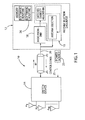
- a receiver system is generally shown at reference identifier 10.
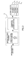
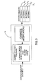
- the receiver system 10 includes a plurality of antenna elements (e.g., A 1 ,A 2 ,A 3 ,A 4,... A N ) configured to receive a transmitted signal, and a receiver device generally indicated at 12 that is in electrical communication with the plurality of antenna elements.
- the receiver system 10 is described herein as the plurality of antenna elements including a first antenna element A 1 , a second antenna element A 2 , a third antenna element A 3 , and a fourth antenna element A 4 .
- the plurality of antenna elements can include two or more antenna elements or effective antennas created by combining or by altering/tapping one or more antenna elements, and the description herein should not be limited to the exemplary embodiment of the first, second, third, and fourth antenna elements A 1 ,A 2 ,A 3 , and A 4 .
- the receiver device 12 is configured to emit an output based upon the received signal, and communicate a control signal that corresponds to a determined signal quality of the received signal.
- the receiver system 10 further includes a switch device 14 adapted to switch among the plurality of antenna elements A 1 ,A 2 ,A 3 ,A 4 to electrically connect a selected antenna element of the plurality of antenna elements A 1 ,A 2 ,A 3 ,A 4 to the receiver device 12.
- the receiver system 10 includes a controller generally indicated at 16, which is shown as part of and in communication with the receiver device 12, such that the controller 16 receives the control signal, wherein the controller 16 commands the switch device 14 to directly switch to any of the plurality of antenna elements A 1 ,A 2 ,A 3 ,A 4 to electrically connect one of the plurality of antenna elements A 1 ,A 2 ,A 3 ,A 4 (e.g., the selected antenna element) to the receiver device 12 based upon the control signal, as described in greater detail herein.
- a controller generally indicated at 16 which is shown as part of and in communication with the receiver device 12, such that the controller 16 receives the control signal, wherein the controller 16 commands the switch device 14 to directly switch to any of the plurality of antenna elements A 1 ,A 2 ,A 3 ,A 4 to electrically connect one of the plurality of antenna elements A 1 ,A 2 ,A 3 ,A 4 (e.g., the selected antenna element) to the receiver device 12 based upon the control signal, as described in greater detail
- the switch device 14 directly switching to any of the plurality of antenna elements A 1 ,A 2 ,A 3 ,A 4 can be a sequential switch (e.g., the switch device 14 switches from the first antenna element A 1 to the second antenna element A 2 ) or a non-sequential switch (e.g., the switch device 14 switches from the first antenna A 1 to the third antenna element A 3 ).
- the control signal corresponds to the determined signal qualities, such that the control signal includes a command for directly switching to any of the plurality of antenna elements A 1 ,A 2 ,A 3 ,A 4 from the selected antenna element when the determined signal quality of the selected antenna element is below a threshold value.
- the controller 16 can assume, based upon the signal communicated therefrom, what antenna element A 1 ,A 2 ,A 3 ,A 4 is currently selected. This differs from a receiver device that is only capable of sequentially switching among antenna elements (e.g., the command signal is the same signal for each switch command), wherein a switch device may not switch among the antenna elements as commanded (e.g., the switch device does not receive or process the command signal), and a controller can incorrectly assume which antenna element is electrically connected to the receiver device.
- a receiver device that is only capable of sequentially switching among antenna elements (e.g., the command signal is the same signal for each switch command), wherein a switch device may not switch among the antenna elements as commanded (e.g., the switch device does not receive or process the command signal), and a controller can incorrectly assume which antenna element is electrically connected to the receiver device.
- a controller may not know which antenna element is currently selected, whereas the controller 16 is more robust, in that the direct control (e.g., the control signal corresponding to one of the plurality of antenna elements A 1 ,A 2 ,A 3 ,A 4 ) allows the controller 16 to know which antenna element A 1 ,A 2 ,A 3 ,A 4 is currently selected with higher confidence or probability.
- the direct control e.g., the control signal corresponding to one of the plurality of antenna elements A 1 ,A 2 ,A 3 ,A 4
- the controller 16 allows the controller 16 to know which antenna element A 1 ,A 2 ,A 3 ,A 4 is currently selected with higher confidence or probability.
- the signal quality is determined by a switched diversity algorithm.
- the switched diversity algorithm implemented to determine the signal quality is calculating and analyzing a signal-to-noise (SNR) ratio, such that the determined SNR is compared to a threshold value.
- SNR signal-to-noise
- One exemplary system and method of switched diversity is U.S. Patent Application Publication No. 2007/0249312 A1 , entitled “RF RECEIVER SYSTEM HAVING SWITCHED ANTENNA DIVERSITY MODULE,” which is hereby incorporated herein by reference in its entirety.
- the determined signal quality can be other measurable forms of measuring a signal quality of a received signal.
- the receiver device 12 includes radio front-end circuitry 18 that receives the signal communicated from the plurality of antenna elements A 1 ,A 2 ,A 3 ,A 4 and transmits a signal to the controller 16.
- the radio front-end circuitry 18 can include, but is not limited to, one or more filters, one or more low-noise amplifiers (LNAs), a down conversion mixer, the like, or a combination thereof.
- LNAs low-noise amplifiers
- the controller 16 can be hardware and/or software, such as, but not limited to, a processor that executes one or more software routines stored in memory 26 for determining the signal quality of the received signal and determining which antenna element of the plurality of antenna elements A 1 ,A 2 ,A 3 ,A 4 the switch device 14 should directly switch to or select.
- Other controller circuitry such as application-specific integrated circuitry (ASIC), may be employed, according to other embodiments.
- a single electrically conductive element 20 electrically connects the receiver device 12 and the switch device 14, according to one embodiment.
- the signal received by the selected antenna element and the control signal are both communicated between the receiver device 12 and the switch device 14 with the single electrically conductive element 20.
- the electrically conductive element 20 can be, but are not limited to, a coaxial cable, electrically conductive wire, optical communicative wire, such as fiber optics, the like, or a combination thereof.
- an electrical power can be supplied to the switch device 14 from a power source 23 along the first electrically conductive element 20.
- the power source 23 can be, but is not limited to, a direct current (DC) power source.
- the electrical power supplied from the power source 23 to the switch device 14 is supplied along a second electrically conductive element 25.
- the controller 16 can command the switch device 14 to switch among the plurality of antenna elements A 1 ,A 2 ,A 3 ,A 4 sequentially based upon the received control signal, according to one embodiment.
- the direct switching from an antenna element to another antenna element of the plurality of antenna elements A 1 ,A 2 ,A 3 ,A 4 can be a sequential switching (e.g., switch from the first antenna element A 1 to a second antenna element A 2 ) or a non-sequential switching (e.g., switch from the first antenna element A 1 to the second antenna element A 3 ).
- the control signal includes a command for the switch device 14 to switch to a particular antenna element of the plurality of antenna elements A 1 ,A 2 ,A 3 ,A 4 , and thus, the antenna element the switch device 14 is switching to can be in sequential order to the currently selected antenna element (e.g., the switch device 14 switching from the first antenna element A 1 to the second antenna element A 2 ).
- the control signal can command the switch device 14 to switch to the next sequential antenna element from the currently selected antenna element without regard to the designated indicator of the plurality of antenna elements A 1 ,A 2 ,A 3 ,A 4 , such that the control signal does not directly correspond to one of the plurality of antenna elements A 1 ,A 2 ,A 3 ,A 4 , but instead includes a command to switch to the next antenna element in sequential order from the currently selected antenna element.
- the control signal can be a universal control signal so that the same command signal is being used for all the switching commands, since the antenna elements do not need to be identified in the control signal.
- the switch device 14 is configured to receive a control signal that identifies a specific antenna element to be switched to, and a universal control signal, so that the switch device 14 switches to the next sequential antenna element from the currently selected antenna element.
- each of the plurality of antenna elements A 1 ,A 2 ,A 3 ,A 4 have a designated voltage potential, such that the control signal includes an electrical power supplied at a voltage potential so that the controller 16 commands the switch device 14 to switch to one of the plurality of antenna elements A 1 ,A 2 ,A 3 ,A 4 , which has the designated voltage potential value that corresponds to the voltage potential of the control signal.
- the first antenna element A 1 can have a designated voltage potential value of zero (0) Volts
- the second antenna element A 2 can have a designated voltage potential value of one-third (1/3) Volts
- the third antenna element A 3 can have a designated voltage potential of two-thirds (2/3) Volts
- the fourth antenna element A 4 can have a designated voltage potential of one (1) Volt, in an exemplary embodiment.
- the switch device 14 can directly switch to the antenna element that has the corresponding designated voltage potential, which can provide for a selective switching among antenna elements (e.g., the switch device 14 switching from the first antenna element A 1 to the third antenna element A 3 ).
- each of the plurality of antenna elements A 1 ,A 2 ,A 3 ,A 4 can have a designated electrical current value, such that the control signal includes an electrical power with an electrical current supplied to the switch device 14 so that the controller 16 commands the switch device 14 to switch to one of the plurality of antenna elements A 1 ,A 2 ,A 3 ,A 4 , which has a designated electrical current value that corresponds to the electrical current of the control signal.
- the designated electrical current value of the first antenna element A 1 is zero Amperes (0A or Amps)
- the designated electrical current value of the second antenna element A 2 is one-third Amps (1/3A)
- the designated electrical current value of the third antenna element A 3 is two-thirds Amps (2/3A)
- the designated electrical current value of the fourth antenna element A 4 is one Amp (1A), in an exemplary embodiment.
- the switch device 14 can directly switch to the antenna element that has the corresponding designated electrical current value, which can provide for a selected switching among antenna elements (e.g., the switch device 14 switching from the first antenna element A 1 to the third antenna element A 3 ).
- each of the plurality of antenna elements A 1 ,A 2 ,A 3 ,A 4 has a designated value and the control signal is modulated, such that the controller 16 commands the switch device 14 to switch to one of the plurality of antenna elements A 1 ,A 2 ,A 3 ,A 4 , which has a designated value that corresponds to the modulated control signal.
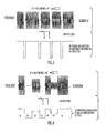
- the control signal can be modulated, such that the amplitude of the signal is varied, the duty cycle of the signal is varied (e.g., pulse width modulation (PWM)), binary data is included in the control signal, multi-level data is included in the control signal, the like, or a combination thereof.
- PWM pulse width modulation
- the control signal is modulated to create pulses of equal value, such that the controller 16 is commanding the switch device 14 to switch among the plurality of antenna elements A 1 ,A 2 ,A 3 ,A 4 sequentially.
- the modulated signal is illustrated having different pulses, wherein each different modulated pulse corresponds to one of the plurality of antenna elements A 1 ,A 2 ,A 3 ,A 4 , which the controller 16 is commanding the switch device 14 to directly switch to the corresponding antenna element.
- the amplitude of the pulse can correspond to a value designated to one of the plurality of antenna elements A 1 ,A 2 ,A 3 ,A 4 .
- the receiver system 10 can be integrated with a vehicle 24 ( Fig. 7 ), according to one embodiment.
- the receiver system 10 can be mobile by being a mobile device (e.g., handheld), or integrate with other mobile devices or apparatuses.
- at least one transmitter 28 transmits a radio frequency (RF) signal, which is received by the receiver device 12.
- RF radio frequency
- the signal can be transmitted at other suitable frequencies, such as, but not limited to, a communication satellite.
- the vehicle 24 can be mobile, such that the controller 16 can command the switch device 14 to switch to a desired antenna element A 1 ,A 2 ,A 3 ,A 4 if the currently selected antenna element is receiving the signal at an undesirable signal quality (e.g., below the threshold value). Additionally, by switching among the plurality of antenna elements A 1 ,A 2 ,A 3 ,A 4 in any order, the controller 16 does not have to switch between a series of antenna elements to electrically connect the desired antenna element to the receiver device 12.
- the controller 16 commands the switch device 14 to switch to the third antenna element A 3 , then the control signal communicated to the switch device 14 can command the switch device 14 to switch directly from the first antenna element A 1 to the third antenna element A 3 without switching to the second antenna element A 2 . Therefore, the output emitted by the receiver device 12 is not affected by an undesirable connection to the second antenna element A 2 , as it would be if the switch device 14 sequentially switched among the antenna elements A 1 ,A 2 ,A 3 ,A 4 .
- the receiver device 12 can include memory 26, such that the memory 26 is configured to store a history of the determined signal quality for at least a portion of the plurality of antenna elements A 1 ,A 2 ,A 3 ,A 4 over a period of time, such that the control signal is based upon the signal quality of the selected antenna element and the stored history of the determined signal qualities, according to one embodiment.
- the stored history can be a recent history, such that the recent stored history represents the signals received by the plurality of antenna elements A 1 ,A 2 ,A 3 ,A 4 , since the vehicle 24 had lost power or turned off.
- the controller 16 can command the switch device 14 to directly switch to any of the other of the plurality of antenna elements A 1 ,A 3 ,A 4 , and skip the second antenna element A 2 in order to prevent an undesirable output from the signal received by the second antenna element A 2 .
- the switch device 14 were to sequentially switch among the plurality of antenna elements A 1 ,A 2 ,A 3 ,A 4 , the receiver device 12 would emit the output based upon the signal received by the second antenna element A 2 to determine the signal reception is insufficient, that another antenna element should be used, and the switch device 14 should switch to the third antenna element A 3 .
- the controller 16 can command the switch device 14 to directly switch to any of the plurality of antenna elements A 1 ,A 2 ,A 3 ,A 4 by implementing a switching algorithm (e.g., executing one or more software routines) that can result in sequential or non-sequential switches.
- a switching algorithm e.g., executing one or more software routines
- the controller 16 can command the switch device 14 to switch to the second antenna element A 2 (i.e., a sequential switch), and if the signal quality of the second antenna element A 2 is worse than the signal quality of the first antenna element A 1 , then the controller 16 can command the switch device 14 to switch back to the first antenna element A 1 .
- the controller 16 can command the switch device 14 to switch to the third antenna element (i.e., a non-sequential switch).
- the switch device 14 can command the switch device 14 to switch to the third antenna element (i.e., a non-sequential switch).
- the third antenna element i.e., a non-sequential switch.
- other adequate switching algorithms can be used that include a direct switch among antenna elements that results in a sequential switching, a non-sequential switching, or a combination thereof.
- a method of switching between a plurality of antenna elements A 1 ,A 2 ,A 3 ,A 4 is generally shown in Fig. 8 at reference identifier 100.
- the method 100 starts at step 102, and proceeds to step 104, wherein a signal is received by a currently selected antenna element A 1 ,A 2 ,A 3 ,A 4 .
- the switch device 14 electrically connects the selected antenna element to the receiver device 12, such that the receiver device 12 is emitting an output based upon the signal received by the selected antenna element.
- the method 100 then proceeds to step 106, wherein the signal quality of the received signal is determined.
- the signal quality of the received signal is determined by using a switched diversity.
- step 108 it is determined if the signal quality is above a threshold value. If it is determined at decision step 108 that the signal quality is above the threshold value, then the method 100 proceeds to step 109, wherein the control signal is communicated to maintain the currently selected antenna element. The method 100 can then return to step 104, wherein the signal is continued to be received by the currently selected antenna element.
- step 110 the control signal is communicated.
- the control signal is communicated from the controller 16, which determines the signal quality of the currently received signal, and the control signal is communicated to the switch device 14.
- the switch device 14 switches among the plurality of antenna elements A 1 ,A 2 ,A 3 ,A 4 based upon the control signal.
- the method 100 can then return to step 104, wherein the signal is received by a currently selected antenna element.
- the switch device 14 directly switches among the plurality of antenna elements A 1 ,A 2 ,A 3 ,A 4 to any of the other antenna elements of the plurality of antenna elements A 1 ,A 2 ,A 3 ,A 4 .
- the receiver system 10 and method 100 can directly switch to any of the plurality of antenna elements A 1 ,A 2 ,A 3 ,A 4 based upon at least the signal quality of the currently received signal.
- the history of signal qualities can be stored for each antenna element A 1 ,A 2 ,A 3 ,A 4 , such that the antenna elements A 1 ,A 2 ,A 3 ,A 4 are switched among based upon the determined signal quality and the stored history of signal qualities for each antenna element. Therefore, if it is anticipated that the signal quality of one of the antenna elements is going to be undesirable, the switch device 14 can switch directly from the currently selected antenna element to another one of the plurality of antenna elements A 1 ,A 2 ,A 3 ,A 4 .
- a single electrically conductive element e.g., electrically conductive element 20
- electrically conductive element 20 can be used to communicate the control signal and the received signal between the receiver device 12 and the switch device 14. It should be appreciated by those skilled in the art that additional or alternative advantages can result from the receiver system 10 and method 100. It should further be appreciated by those skilled in the art that the above elements described in the receiver system 10 and method 100 can be combined in alternative ways.
Landscapes
- Engineering & Computer Science (AREA)
- Computer Networks & Wireless Communication (AREA)
- Signal Processing (AREA)
- Radio Transmission System (AREA)
- Variable-Direction Aerials And Aerial Arrays (AREA)
- Circuits Of Receivers In General (AREA)
Applications Claiming Priority (1)
| Application Number | Priority Date | Filing Date | Title |
|---|---|---|---|
| US12/150,414 US8107915B2 (en) | 2008-04-28 | 2008-04-28 | Receiver system and method for receiving signals |
Publications (2)
| Publication Number | Publication Date |
|---|---|
| EP2114022A2 true EP2114022A2 (de) | 2009-11-04 |
| EP2114022A3 EP2114022A3 (de) | 2011-11-09 |
Family
ID=40908443
Family Applications (1)
| Application Number | Title | Priority Date | Filing Date |
|---|---|---|---|
| EP09158075A Withdrawn EP2114022A3 (de) | 2008-04-28 | 2009-04-16 | Empfängersystem und Verfahren zum Empfangen von Signalen |
Country Status (2)
| Country | Link |
|---|---|
| US (1) | US8107915B2 (de) |
| EP (1) | EP2114022A3 (de) |
Cited By (1)
| Publication number | Priority date | Publication date | Assignee | Title |
|---|---|---|---|---|
| TWI646790B (zh) * | 2017-01-27 | 2019-01-01 | 日商日本電信電話股份有限公司 | Wireless base station and control method thereof |
Families Citing this family (8)
| Publication number | Priority date | Publication date | Assignee | Title |
|---|---|---|---|---|
| CA2731034A1 (en) * | 2008-06-30 | 2010-01-14 | Sirius Xm Radio Inc. | Interface between a switched diversity antenna system and a digital radio receiver |
| US9042323B1 (en) * | 2013-01-18 | 2015-05-26 | Sprint Spectrum L.P. | Method and system of activating a global beam in a coverage area |
| US9191991B2 (en) * | 2013-02-27 | 2015-11-17 | Blackberry Limited | Methods and apparatus for reducing the impact of RF interference based on estimation of colored noise |
| JP5803983B2 (ja) * | 2013-06-07 | 2015-11-04 | 株式会社デンソー | 通信装置 |
| WO2015022594A1 (en) | 2013-08-15 | 2015-02-19 | Koninklijke Philips N.V. | Patient monitoring involving receiving multiple asynchronous data streams with antenna diversity |
| JP2015104054A (ja) * | 2013-11-27 | 2015-06-04 | 株式会社日立国際電気 | 受信装置 |
| KR101589214B1 (ko) * | 2014-09-23 | 2016-01-27 | 현대자동차주식회사 | 차량에서의 안테나 제어 방법 및 장치 |
| EP3422609A1 (de) * | 2017-06-30 | 2019-01-02 | Thomson Licensing | Verfahren zur erfassung einer externen, mit einer kommunikationsvorrichtung verbundenen antenne |
Citations (6)
| Publication number | Priority date | Publication date | Assignee | Title |
|---|---|---|---|---|
| WO1997044978A1 (en) * | 1996-05-22 | 1997-11-27 | Nokia Telecommunications Oy | Method and system for selecting an antenna beam of a base station of a radio system |
| CA2505712A1 (en) * | 2001-11-02 | 2003-05-08 | Soma Networks, Inc. | System and method for mitigating fading of a signal at a radio receiver |
| US20030171099A1 (en) * | 2002-03-08 | 2003-09-11 | Interdigital Technology Corporation | Method and system for implementing smart antennas and diversity techniques |
| FR2842373A1 (fr) | 2002-07-09 | 2004-01-16 | Imra Europe Sa | Procede de selection de signaux d'antennes dans un systeme de diversite d'antennes |
| DE102006006266A1 (de) | 2005-02-13 | 2006-08-24 | Lindenmeier, Heinz, Prof. Dr. Ing. | Anlage zum Empfang von digital modulierten Funksignalen zu einem Fahrzeug unter Verwendung von Antennendiversity |
| EP1848118A2 (de) | 2006-04-20 | 2007-10-24 | Delphi Technologies, Inc. | HF-Empfängersystem mit schaltbarem Antennendiversitätsmodul |
Family Cites Families (9)
| Publication number | Priority date | Publication date | Assignee | Title |
|---|---|---|---|---|
| DE3006627A1 (de) * | 1980-02-22 | 1981-08-27 | Robert Bosch Gmbh, 7000 Stuttgart | Verfahren zum stoerungsfreien empfangen von ukw-signalen in fahrzeugen |
| US5095535A (en) * | 1988-07-28 | 1992-03-10 | Motorola, Inc. | High bit rate communication system for overcoming multipath |
| DE4441761A1 (de) | 1994-11-23 | 1996-05-30 | Lindenmeier Heinz | Mehrantennen-Scanning-Diversitysystem für Fahrzeuge |
| EP1182800B1 (de) | 2000-08-24 | 2009-04-15 | Continental Automotive GmbH | Empfangssystem mit Antennendiversität |
| US7180444B2 (en) | 2005-06-16 | 2007-02-20 | Delphi Technologies, Inc. | System and method for determining a velocity and a direction of travel of a vehicle on a roadway |
| US7324043B2 (en) | 2005-09-02 | 2008-01-29 | Delphi Technologies, Inc. | Phase shifters deposited en masse for an electronically scanned antenna |
| US7558555B2 (en) * | 2005-11-17 | 2009-07-07 | Delphi Technologies, Inc. | Self-structuring subsystems for glass antenna |
| US7609203B2 (en) | 2005-12-14 | 2009-10-27 | Delphi Technologies, Inc. | Method for ephemeris assisted global positioning |
| US7230569B1 (en) | 2005-12-23 | 2007-06-12 | Delphi Technologies, Inc. | Search algorithm for phased array antenna |
-
2008
- 2008-04-28 US US12/150,414 patent/US8107915B2/en active Active
-
2009
- 2009-04-16 EP EP09158075A patent/EP2114022A3/de not_active Withdrawn
Patent Citations (6)
| Publication number | Priority date | Publication date | Assignee | Title |
|---|---|---|---|---|
| WO1997044978A1 (en) * | 1996-05-22 | 1997-11-27 | Nokia Telecommunications Oy | Method and system for selecting an antenna beam of a base station of a radio system |
| CA2505712A1 (en) * | 2001-11-02 | 2003-05-08 | Soma Networks, Inc. | System and method for mitigating fading of a signal at a radio receiver |
| US20030171099A1 (en) * | 2002-03-08 | 2003-09-11 | Interdigital Technology Corporation | Method and system for implementing smart antennas and diversity techniques |
| FR2842373A1 (fr) | 2002-07-09 | 2004-01-16 | Imra Europe Sa | Procede de selection de signaux d'antennes dans un systeme de diversite d'antennes |
| DE102006006266A1 (de) | 2005-02-13 | 2006-08-24 | Lindenmeier, Heinz, Prof. Dr. Ing. | Anlage zum Empfang von digital modulierten Funksignalen zu einem Fahrzeug unter Verwendung von Antennendiversity |
| EP1848118A2 (de) | 2006-04-20 | 2007-10-24 | Delphi Technologies, Inc. | HF-Empfängersystem mit schaltbarem Antennendiversitätsmodul |
Cited By (1)
| Publication number | Priority date | Publication date | Assignee | Title |
|---|---|---|---|---|
| TWI646790B (zh) * | 2017-01-27 | 2019-01-01 | 日商日本電信電話股份有限公司 | Wireless base station and control method thereof |
Also Published As
| Publication number | Publication date |
|---|---|
| US20090270059A1 (en) | 2009-10-29 |
| EP2114022A3 (de) | 2011-11-09 |
| US8107915B2 (en) | 2012-01-31 |
Similar Documents
| Publication | Publication Date | Title |
|---|---|---|
| US8107915B2 (en) | Receiver system and method for receiving signals | |
| EP2107640A1 (de) | Empfängersystem zum Empfang von analogen und digitalen Signalen | |
| AU739043B2 (en) | Selective diversity combining | |
| EP1848118B1 (de) | Hf-empfängersystem mit schaltbarem antennendiversitätsmodul | |
| US7697913B2 (en) | Dual tuner diversity for background processing and to reduce multipath distortion | |
| US8385868B2 (en) | Diversity antenna system and method utilizing a threshold value | |
| EP2541799B1 (de) | Diversität mit Identifizierung spezifischer Antenneneigenschaften und deren Bewertung | |
| MXPA02002320A (es) | Sistema en diversidad para recibir senales de radio terrestres y/o satelital, digitales, para vehiculos automotores. | |
| JP2003283405A (ja) | 車載デジタル通信受信装置およびアンテナ | |
| US8483339B2 (en) | Communication apparatus and communication process method | |
| US8660511B2 (en) | Antenna diversity scheme employing band pass sampling and fast semiconductor switching | |
| US7349720B2 (en) | Power efficient signal acquisition with multiple receive antennas | |
| US20070037538A1 (en) | Technique for reducing multipath interference in an FM receiver | |
| US8170161B2 (en) | Hybrid switched-phased diversity system and method | |
| EP1753156B1 (de) | Gewichtsberechnungsverfahren zur Diversity-Kombination in einem FM-Empfänger | |
| JP3103043U (ja) | デジタルテレビジョン信号のダイバーシチ受信回路 | |
| WO2013182496A1 (en) | Mimo signal transmission and reception device and system comprising at least one such device | |
| US20090060106A1 (en) | Diversity device | |
| EP1965524B1 (de) | System und Verfahren eines Stereoempfangssystems | |
| JP3142595U (ja) | 自動車用のデジタル地上及び/又は衛星無線信号を受信するためのダイバーシチ受信装置 | |
| JP2009147557A (ja) | 車載用地上デジタルテレビの受信システム及び指向性可変アンテナの指向性ピーク方向の設計方法 | |
| EP2009814A1 (de) | System und Verfahren zum Empfangen und Kombinieren von mehreren Antennensignalen | |
| JPH08146117A (ja) | ダイバーシチ受信装置 | |
| JPH09148973A (ja) | ダイバーシティ受信装置 | |
| JPH07170220A (ja) | ダイバーシティ受信装置 |
Legal Events
| Date | Code | Title | Description |
|---|---|---|---|
| PUAI | Public reference made under article 153(3) epc to a published international application that has entered the european phase |
Free format text: ORIGINAL CODE: 0009012 |
|
| AK | Designated contracting states |
Kind code of ref document: A2 Designated state(s): AT BE BG CH CY CZ DE DK EE ES FI FR GB GR HR HU IE IS IT LI LT LU LV MC MK MT NL NO PL PT RO SE SI SK TR |
|
| PUAL | Search report despatched |
Free format text: ORIGINAL CODE: 0009013 |
|
| AK | Designated contracting states |
Kind code of ref document: A3 Designated state(s): AT BE BG CH CY CZ DE DK EE ES FI FR GB GR HR HU IE IS IT LI LT LU LV MC MK MT NL NO PL PT RO SE SI SK TR |
|
| RIC1 | Information provided on ipc code assigned before grant |
Ipc: H04B 7/08 20060101AFI20111004BHEP |
|
| 17P | Request for examination filed |
Effective date: 20120509 |
|
| 17Q | First examination report despatched |
Effective date: 20160630 |
|
| STAA | Information on the status of an ep patent application or granted ep patent |
Free format text: STATUS: THE APPLICATION IS DEEMED TO BE WITHDRAWN |
|
| 18D | Application deemed to be withdrawn |
Effective date: 20161111 |