EP2114272B1 - Wirbelsäulen-versteifungsvorrichtung und relevantes verfahren - Google Patents
Wirbelsäulen-versteifungsvorrichtung und relevantes verfahren Download PDFInfo
- Publication number
- EP2114272B1 EP2114272B1 EP07853993.9A EP07853993A EP2114272B1 EP 2114272 B1 EP2114272 B1 EP 2114272B1 EP 07853993 A EP07853993 A EP 07853993A EP 2114272 B1 EP2114272 B1 EP 2114272B1
- Authority
- EP
- European Patent Office
- Prior art keywords
- brace
- hub
- central member
- connecting element
- saddle
- Prior art date
- Legal status (The legal status is an assumption and is not a legal conclusion. Google has not performed a legal analysis and makes no representation as to the accuracy of the status listed.)
- Not-in-force
Links
- 238000000034 method Methods 0.000 title description 15
- 230000006641 stabilisation Effects 0.000 claims description 25
- 238000011105 stabilization Methods 0.000 claims description 25
- 230000004927 fusion Effects 0.000 description 17
- 239000000463 material Substances 0.000 description 12
- 238000009434 installation Methods 0.000 description 5
- 238000001356 surgical procedure Methods 0.000 description 5
- 238000005452 bending Methods 0.000 description 4
- 230000007850 degeneration Effects 0.000 description 4
- 210000000988 bone and bone Anatomy 0.000 description 3
- 229920001971 elastomer Polymers 0.000 description 3
- 239000000806 elastomer Substances 0.000 description 3
- 208000014674 injury Diseases 0.000 description 3
- 229920000049 Carbon (fiber) Polymers 0.000 description 2
- 239000004606 Fillers/Extenders Substances 0.000 description 2
- RTAQQCXQSZGOHL-UHFFFAOYSA-N Titanium Chemical compound [Ti] RTAQQCXQSZGOHL-UHFFFAOYSA-N 0.000 description 2
- 208000027418 Wounds and injury Diseases 0.000 description 2
- 239000004917 carbon fiber Substances 0.000 description 2
- 238000002788 crimping Methods 0.000 description 2
- 230000006378 damage Effects 0.000 description 2
- 238000002347 injection Methods 0.000 description 2
- 239000007924 injection Substances 0.000 description 2
- 230000002427 irreversible effect Effects 0.000 description 2
- VNWKTOKETHGBQD-UHFFFAOYSA-N methane Chemical compound C VNWKTOKETHGBQD-UHFFFAOYSA-N 0.000 description 2
- 230000000399 orthopedic effect Effects 0.000 description 2
- 229920000642 polymer Polymers 0.000 description 2
- 239000002861 polymer material Substances 0.000 description 2
- 125000006850 spacer group Chemical group 0.000 description 2
- 230000000087 stabilizing effect Effects 0.000 description 2
- 229910052719 titanium Inorganic materials 0.000 description 2
- 239000010936 titanium Substances 0.000 description 2
- 208000032170 Congenital Abnormalities Diseases 0.000 description 1
- 244000043261 Hevea brasiliensis Species 0.000 description 1
- 206010028980 Neoplasm Diseases 0.000 description 1
- 239000004696 Poly ether ether ketone Substances 0.000 description 1
- 229910000831 Steel Inorganic materials 0.000 description 1
- 230000032683 aging Effects 0.000 description 1
- 210000003484 anatomy Anatomy 0.000 description 1
- 230000000295 complement effect Effects 0.000 description 1
- 230000001934 delay Effects 0.000 description 1
- 201000010099 disease Diseases 0.000 description 1
- 208000037265 diseases, disorders, signs and symptoms Diseases 0.000 description 1
- 230000000694 effects Effects 0.000 description 1
- 230000035876 healing Effects 0.000 description 1
- 239000007943 implant Substances 0.000 description 1
- 238000002513 implantation Methods 0.000 description 1
- 230000006872 improvement Effects 0.000 description 1
- 238000003780 insertion Methods 0.000 description 1
- 230000037431 insertion Effects 0.000 description 1
- 230000003993 interaction Effects 0.000 description 1
- 238000002684 laminectomy Methods 0.000 description 1
- 210000003041 ligament Anatomy 0.000 description 1
- 229910052751 metal Inorganic materials 0.000 description 1
- 239000002184 metal Substances 0.000 description 1
- 238000012978 minimally invasive surgical procedure Methods 0.000 description 1
- 229920003052 natural elastomer Polymers 0.000 description 1
- 229920001194 natural rubber Polymers 0.000 description 1
- 229910001000 nickel titanium Inorganic materials 0.000 description 1
- 229920001692 polycarbonate urethane Polymers 0.000 description 1
- 229920002530 polyetherether ketone Polymers 0.000 description 1
- 230000008569 process Effects 0.000 description 1
- 230000001737 promoting effect Effects 0.000 description 1
- 238000011084 recovery Methods 0.000 description 1
- 230000004044 response Effects 0.000 description 1
- 230000035939 shock Effects 0.000 description 1
- 238000004513 sizing Methods 0.000 description 1
- 239000007787 solid Substances 0.000 description 1
- 239000010935 stainless steel Substances 0.000 description 1
- 229910001220 stainless steel Inorganic materials 0.000 description 1
- 239000010959 steel Substances 0.000 description 1
- 230000035882 stress Effects 0.000 description 1
- 229920003051 synthetic elastomer Polymers 0.000 description 1
- 230000001225 therapeutic effect Effects 0.000 description 1
- 210000001519 tissue Anatomy 0.000 description 1
- 230000008733 trauma Effects 0.000 description 1
Images




Classifications
-
- A—HUMAN NECESSITIES
- A61—MEDICAL OR VETERINARY SCIENCE; HYGIENE
- A61B—DIAGNOSIS; SURGERY; IDENTIFICATION
- A61B17/00—Surgical instruments, devices or methods
- A61B17/56—Surgical instruments or methods for treatment of bones or joints; Devices specially adapted therefor
- A61B17/58—Surgical instruments or methods for treatment of bones or joints; Devices specially adapted therefor for osteosynthesis, e.g. bone plates, screws or setting implements
- A61B17/68—Internal fixation devices, including fasteners and spinal fixators, even if a part thereof projects from the skin
- A61B17/70—Spinal positioners or stabilisers, e.g. stabilisers comprising fluid filler in an implant
- A61B17/7001—Screws or hooks combined with longitudinal elements which do not contact vertebrae
- A61B17/7002—Longitudinal elements, e.g. rods
- A61B17/7019—Longitudinal elements having flexible parts, or parts connected together, such that after implantation the elements can move relative to each other
- A61B17/7031—Longitudinal elements having flexible parts, or parts connected together, such that after implantation the elements can move relative to each other made wholly or partly of flexible material
-
- A—HUMAN NECESSITIES
- A61—MEDICAL OR VETERINARY SCIENCE; HYGIENE
- A61B—DIAGNOSIS; SURGERY; IDENTIFICATION
- A61B17/00—Surgical instruments, devices or methods
- A61B17/56—Surgical instruments or methods for treatment of bones or joints; Devices specially adapted therefor
- A61B17/58—Surgical instruments or methods for treatment of bones or joints; Devices specially adapted therefor for osteosynthesis, e.g. bone plates, screws or setting implements
- A61B17/68—Internal fixation devices, including fasteners and spinal fixators, even if a part thereof projects from the skin
- A61B17/70—Spinal positioners or stabilisers, e.g. stabilisers comprising fluid filler in an implant
- A61B17/7058—Plates mounted on top of bone anchor heads or shoulders
Definitions
- This invention relates generally to therapeutic and corrective devices and methods for the spine and more specifically relates to devices and methods for stiffening the spine.
- the spine includes a series of joints routinely called motion segment units, which is the smallest component of the spine that exhibits kinematic behavior characteristic of the entire spine.
- the motion segment unit is capable of flexion, extension, lateral bending and translation.
- the components of each motion segment unit include two adjacent vertebrae and their apophyseal joints, the intervertebral disc, and the connecting ligamentous tissue. Each component of the motion segment unit contributes to the mechanical stability of the joint.
- Treatment may include fusion, discectomy, or laminectomy.
- fusion or rigid stabilization is the immobilization of a motion segment unit.
- fusion or rigid stabilization of one or more motion segment units may be an important element of a surgical procedure in I certain cases (i.e., injuries, deformities, tumors, etc.). In other cases it is a complementary element (i.e., fusion performed due to degeneration).
- One current spinal surgical technique typically involves fusing one or more unstable motion segment units and possibly, the removal of ligaments, bone, disc, or combinations thereof included in the unstable motion segment unit or units prior to fusing.
- fusion often involves several disadvantages.
- the fusing process results in a permanent or rigid internal fixation of all or part of the intervertebral joints and usually involves metallic rods, plates, and the like for stabilization.
- Such systems are intended to rigidly immobilize the motion segment unit to promote fusion within that motion segment unit resulting in a loss of mobility.
- Fusion also causes the mobility of the motion segment to be transferred to other motion segments of the spine.
- the added stresses transferred to motion segments neighboring or nearby the fused segment can cause or accelerate degeneration of those segments.
- Another disadvantage of fusion is that it is an irreversible procedure.
- a dynamic stabilization system is provided by the assignee of this invention under the trademark DYNESYS® as generally described in European Patent Application No. 0669109A1 .
- DYNESYS® As generally described in European Patent Application No. 0669109A1 .
- Such a dynamic stabilization system utilizes pedicle screws installed into appropriate locations in adjacent vertebrae. Flexible materials in conjunction with the pedicle screws are used rather than rigid orthopedic rods or bone grafts alone as an adjunct fusion.
- a tubular spacer is positioned between the pedicle screws on adjacent vertebrae with a tensioned cord passing through the central lumen of the spacer. Dynamic stabilization systems of this type bring the lumbar vertebrae into a desired anatomical position while stabilizing the effective segments and without irreversible fusion.
- Fusion procedures can be improved by modifying the load sharing characteristics of the treated spine and one technique is to allow more of a physiologic loading between pedicular fixation and anterior column support. Additionally, a device and associated method that precludes or at least delays the need for fusion for all but the most advanced degeneration of a motion segment, particularly if such a device would allow close to normal motion and pain relief is desirable. Moreover, utilization of minimally invasive surgical procedures and techniques to install such devices is also a highly desirable objective to enhance and promote patient healing and recovery.
- Document WO 2006/074191 A2 discloses a system according to the preamble of claim 1.
- Document US 2002/0035366 A1 discloses a pedicle screw system with a connector comprising a bore receiving an axial lumen.
- the invention includes a spinal stabilization system having a first and a second vertebral anchor each adapted to be coupled to one of a first and a second vertebrae.
- the system also includes a flexible connecting element coupled to each of the first and second vertebral anchors and extending between the vertebral anchors.
- the connecting element has a central member and a brace positioned about the central member and the central member is stiffer than the brace to provide the needed combination of support and stiffness to the construct while offering flexibility.
- a spine stiffening stabilization system 10 includes a connecting element 12 coupled to and extending between a pair of vertebral anchors 14.
- Each vertebral anchor 14 is adapted to couple to either of two vertebras 16 in a patient's spine 18.
- the connecting element 12 With the connecting element 12 secured to the vertebral anchors 14, the connecting element 12 maintains a restored disc space height and/or alignment between the adjacent vertebrae 16. In one form, the connecting element 12 preserves motion between the adjacent vertebrae 16.
- the vertebral anchor 14 is a polyaxial, top loading pedicle screw including a threaded shaft 20 adapted to be inserted into a pedicle area 22 of the vertebrae 16.
- the vertebral anchor includes a head 24 on the threaded shaft 20 and a saddle 26 is coupled to the head 24 and is adapted for polyaxial movement of the saddle 26 relative to the shaft 20.
- the saddle 26 having an exemplary U-shape provides a top loading capability to the vertebral anchor 14 so that the connecting element 12 may be inserted downwardly into the saddle 26 between a pair of polyaxial head receiving arms 28.
- the saddle 26 can be constructed with any desired shape.
- a securing member in the form of a threaded set screw 30 mates with the saddle 26 to secure the connecting element 12 to the vertebral anchor 14.
- Each receiving arm 28 of the U-shaped saddle 26 has threads 32 which mate with the threads 34 on the set screw securing member 30.
- a top loading polyaxial pedicle screw is shown and described herein as one embodiment of the vertebral anchor 14, other types of vertebral anchors can readily be used within the scope of this invention including standard fixed pedicle screws, hooks or other devices intended to couple a connecting element to the vertebrae.
- one example of the connecting element 12 includes a central portion or member 36 and a pair of connecting portions or shanks 38 that include rod portions 39 that can be of any suitable shape to fit within the saddle 26 extending in opposite directions on the connecting element 12.
- Each shank 38 is coupled to one of the vertebral anchors 14.
- the terminal ends of the shanks 38 of the various embodiments of this invention can be trimmed to length after sizing and installation.
- the connecting members 38 can be pre-sized prior to implementation.
- the central member 36 is concentrically surrounded by a flexible portion or brace 40.
- the brace 40 is positioned between spaced flanges 42 and the central member 36 is secured within the brace 40 and between the flanges 42 by crimping tabs 44.
- the connecting element 12 includes a flexible intermediate portion 46.
- the brace 40 and central member 36 can be intended for use in the intermediate portion 46.
- a solid flexible core can be used as the flexible intermediate portion 46.
- the brace 40 is an elastomeric member that allows for flexing of the connecting element 12.
- the brace 40 stabilizes the spine 18 while allowing for flexibility and axial dampening.
- the central member 36 may be tensioned and integral to the intermediate portion 46 of the connecting element 12.
- the central member 36 allows for bending of the shanks 38 and the associated forces on the brace 40.
- the connecting element 12 of this invention allows for flexing of the spinal stabilization system 10 in response to movement of the vertebrae 16.
- connecting element 12 of Figs. 1-3 allows for bending of the connecting element 12 and the shanks 38 connected to the vertebral anchors 14 so that the central member 36 is placed under tension and one side of the brace 40 is compressed depending upon the orientation of the bending motion.
- FIG. 4 a cross-sectional view of an alternative example of the connecting element 12 is shown in which the shanks 38 are connected to a pair of spaced outer flanges 42 between which the flexible brace 40 is positioned.
- the central member 36 is embedded within the brace 40 and includes an additional pair of spaced inner flanges 48 between which a portion of the central member 36 is held by mechanical crimping tabs 44 or similar arrangement.
- Each of the inner flanges 48 is mounted and spaced from an associated outer flange 42 by an extension 50 of the shank 38 extending into the brace 40.
- the central member 36 allows the shanks 38 and flanges 42 when bent to apply both compressive and tensile forces to the brace 40 as well as tension to the central member 36.
- the central member 36 may be made from a DacronTM tape woven cord, a braided stainless steel or titanium cable, carbon fiber, KevlarTM or a variety of other materials providing sufficient strength with low elongation characteristics.
- Other options for the central member 36 include a synthetic or natural rubber woven cord which is stretched between the flanges 42 prior to attachment and mounting therein. The cord would be attached to the flanges 42 and then stretched into a mold cavity where the polymer or elastomer brace material would be injected into the mold so that the central cord would be in constant tension, but below its elastic limit.
- FIG. 5 A further alternative example of the connecting element 12 according to this invention is shown in Fig. 5 in which the central member 36 is surrounded by the brace 40 and oppositely extending shanks 38 mount the connecting element 12 to the respective vertebral anchors 14.
- the central member 36 of Fig. 5 may be en elastic mesh or woven member and the polymer material of the brace 40 would then be injection molded through the mesh and around the corded central member.
- the central member 36 could be steel, titanium, nickel titanium alloy, polymer, carbon fiber or other materials.
- the connecting element 12 is a flexible member that provides a shock absorbing effect in transmitting spinal column loads between the anchors 14 to which it is engaged.
- Intermediate portion 46 between the flanges 42 can also permit relative movement to allow motion of the spinal column segment to which connecting element 12 is engaged.
- intermediate portion 46 provides connecting element 12 with a variable stiffness profile between anchors 14.
- a two-level section system 10 such as the embodiment shown in Fig. 6 could be utilized.
- the construct of Fig. 6 provides two flexible connecting elements 12 wi th a predetermined space between them.
- the length of the shank 38 positioned between the connecting elements 12 of the embodiment of Fig. 6 could be fixed or a variable distance to accommodate different vertebral anatomies.
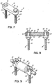
- FIG. 7 A further alternative example of a spinal stabilization stiffening system 10 is shown in perspective view in Fig. 7 and cross-sectional view in Fig. 8 .
- the vertebral anchor 14 of the embodiment of Figs. 7 and 8 is shown as a pedicle screw having a threaded shaft 20 and a head 24.
- the vertebral anchor 14 in one embodiment is a polyaxial pedicle screw similar to a device marketed by Zimmer Spine, Inc. as the ST360TM.
- the vertebral anchor 14 includes an upwardly extending toggle 62.
- the connecting element 12 is mounted to the toggles 62 of the vertebral anchors 14.
- the connecting element 12 in one embodiment includes a central member 36 of an elastomeric or polymeric material providing flexibility to the construct.
- the central member 36 is molded about a pair of rims 64 providing an aperture 66 so that the connecting element 12 may be mounted downwardly onto the toggles 62 and secured in place by a washer 68 and threaded nut 70 combination as shown in Figs. 7 and 8 .
- a further alternative embodiment of the connecting element 12 is shown.
- flanges 38 are provided with outwardly projecting annular hubs 52 and a securing element in the form of a setscrew 54 is seated within a threaded aperture 56 on the hub 52 to secure the flange 42 and hub 52 arrangement to the shank 38 of the connecting element 12 and against the brace 40.
- the connecting element can be assembled pre- or intra-operatively. Once assembled, as shown in Fig. 10A , the connecting element 12 is positioned in the top loading vertebral anchors 14 and secured thereto by the vertebral anchor set screws 30 as shown in Fig. 10B resulting in the arrangement and installation of Fig. 9 .
- the intermediate portion 46 is of a different size than intermediate portion 46 of Fig. 1 and occupies more of the distance between the securing members 30.
- a cross-sectional view of the connecting element 12 and associated vertebral anchors 14 of Figs. 9-10B is shown in Fig. 11 .
- a multi-level construct 10 is provided with a generally H-shaped hub 58 having a duct 60 there through for the central member 36 to extend from one connecting element 12 to an adjacent connecting element 12.
- the flanges 42 can be adapted to engage the flexible brace 40 there between.
- flanges 42 include holes to receive attachment means such as fasteners, sutures, threads, wires, or other devices to engage central member 36 to the respective flange 42.
- the brace 40 is injection molded between flanges 42. The injected material can flow into holes in the central member 36 to form around central member 36 and at least partially around the flanges 42 to provide engagement therewith.
- intermediate portion 46 is molded over flanges 42.
- the connecting element 12 can be provided with or without the central member 36 and with or without the flanges 42.
- anchor 14 is engageable to a first vertebra 16
- a second anchor 14 is engageable to a second vertebra 16
- a third anchor 14 is engageable to a third vertebra 16.
- intermediate portion 46 allows the vertebrae to which the anchors 14 are engaged to move or flex relative to one another, but limits extension and flexion motion to provide a stabilizing effect.
- Connecting element 12 can be guided into position between the anchors 14 using an installation instrument as discussed above.
- the installation instrument may include extenders extending from any one, two or three of the anchors 14.
- Other techniques contemplate insertion with an open surgical technique, or guiding of the connecting element 12 distally along extenders extending proximally from one or more of the anchors 14.
- Connecting element 12 can be employed in fusion procedures or in procedures employing dynamic stabilization without fusion. In fusion procedures, fusion promoting material and/or one or more fusion devices, implants, or bone graft are placed in the disc space between adjacent vertebrae. In such procedures, a single level connecting element 12 may be coupled between the vertebrae if dynamic stabilization is desired. If rigid stabilization is desired, an elongated connecting element 12 can be provided and engaged between the vertebrae to be fused, and one or more adjacent vertebral levels can be dynamically stabilized with the intermediate portion 46 engaged between these or more other vertebral levels.
- the connecting elements 12 are shown as being adapted to extend along one or two vertebral levels, the connecting elements 12 can also extend along three or more vertebral levels.
- one of the shanks 38 can include a length that extends along multiple vertebral levels to be fused to provide rigid stabilization of these levels, while the other of the shanks 38 includes a length adapted to extend along at least one vertebral level to provide a flexible intermediate portion 46 between vertebrae 16 for dynamic stabilization.
- the flexible brace 40 discussed herein can be made from any suitable material allowing at some motion of the vertebral level along which the intermediate portion 46 is engaged.
- the brace portions 40 can be made from elastomers, polycarbonateurethane, polyetheretherketone, or other polymer material.
- the brace 40 can be made from resorbable material.
- the brace 40 include springs, which can be made from metal or other suitable material.
- the connecting element 12 can be provided with a varying stiffness profiles to vary the stiffness properties of the system 10 and control movement of the one or more dynamically stabilized vertebral levels.
- Such varying stiffness profiles can be provided across the cross-section of a single flexible intermediate portion 46 of a particular connecting element 12, or provided between different intermediate portions 46 of a single multi-level connecting element 12, or provided between a number of connecting elements 12 in a kit where the connecting elements 12 includes one or more portions with a stiffness profile that varies relative to one or more of the portions of the other connecting elements 12.
- the hardness characteristics of the material comprising the flexible brace 40 is varied.
- the durometer of an elastomer material comprising the one or more flexible brace portions 40 may vary to allow selection and implantation of a connecting element 12 providing the desired motion characteristics for the vertebral level.
- the connecting element 12 is provided with a central member 36 that couples the first and second flanges 42 to one another through the flexible brace portion 40.
- the diameter of the central member 36 can be varied so that the connecting elements 12 with flexible brace portions 40 extending about a central member 36 with a greater diameter are stiffer than connecting elements 12 with a flexible brace portion 40 extending about a central member 36 of lesser diameter.
- the central member 36 can be pre-tensioned so that the flanges 42 are compressed against the flexible brace portion 40 when engaged thereto.
- the amount of pre-tension can range from zero to the tensile break strength of the central member 36.
- the greater pre-tension loading of the central member 36 results in stiffer flexible brace portion 40 behavior since the preloading compresses the flexible brace portion 40 between the flanges 42.
Landscapes
- Health & Medical Sciences (AREA)
- Orthopedic Medicine & Surgery (AREA)
- Life Sciences & Earth Sciences (AREA)
- Neurology (AREA)
- Surgery (AREA)
- Heart & Thoracic Surgery (AREA)
- Engineering & Computer Science (AREA)
- Biomedical Technology (AREA)
- Nuclear Medicine, Radiotherapy & Molecular Imaging (AREA)
- Medical Informatics (AREA)
- Molecular Biology (AREA)
- Animal Behavior & Ethology (AREA)
- General Health & Medical Sciences (AREA)
- Public Health (AREA)
- Veterinary Medicine (AREA)
- Prostheses (AREA)
- Surgical Instruments (AREA)
Claims (13)
- Mehrstufiges dynamisches Stabilisierungssystem für eine Wirbelsäule, wobei das System umfasst:einen ersten Wirbelanker (14), der einen Gewindeschaftabschnitt (20), einen Kopfabschnitt (24) und einen Sattel (26) aufweist, der mit dem Kopfabschnitt gekoppelt ist, wobei der Sattel eine U-Form aufweist, der eine Fähigkeit zum Einsetzen von oben zwischen einem Paar von Aufnahmearmen (28), die jeweils ein Gewinde (32) aufweisen, bereitstellt;einen zweiten Wirbelanker (14) mit einem Gewindeschaftabschnitt (20) und einem Kopfabschnitt, der einen sich hindurch erstreckenden Sattel (26) aufweist;einen dritten Wirbelanker (14) mit einem Gewindeschaftabschnitt (20) und einem Kopfabschnitt, der einen sich hindurch erstreckenden Sattel (26) aufweist;eine erste Verstrebung (40), die zwischen dem Kopfabschnitt des ersten Wirbelankers und dem Kopfabschnitt des zweiten Wirbelankers positioniert ist,eine zweite Verstrebung (40), die zwischen dem Kopfabschnitt des ersten Wirbelankers und dem Kopfabschnitt des dritten Wirbelankers positioniert ist;ein Zentralelement (36), das sich durch die erste Verstrebung und durch die zweite Verstrebung erstreckt;dadurch gekennzeichnet, dassdas System ferner eine erste Nabe (58) umfasst, die in dem Sattel des ersten Wirbelankers mit einem Gewindestift (30) gesichert ist, wobei das Gewinde von jedem der Aufnahmearme mit dem Gewinde des Gewindestifts zusammenpasst und wobei sich das Zentralelement durch die erste Nabe erstreckt.
- System nach Anspruch 1, wobei die erste Nabe (58) einen ersten Flansch (42) aufweist, der zum Eingriff mit der ersten Verstrebung (40) angepasst ist.
- System nach Anspruch 2, wobei die erste Nabe (58) einen zweiten Flansch (42) aufweist, der zum Eingriff mit der zweiten Verstrebung (40) angepasst ist.
- System nach Anspruch 1, ferner mit einer zweiten Nabe (52), die in dem Sattel (26) des zweiten Wirbelankers (14) angeordnet ist, wobei sich das Zentralelement (36) in die zweite Nabe erstreckt.
- System nach Anspruch 4, wobei die zweite Nabe (52) in dem Sattel (26) des Kopfabschnitts (24) des zweiten Wirbelankers (14) mit einem Gewindestift (30) gesichert ist.
- System nach Anspruch 4, wobei die zweite Nabe (52) einen Flansch (42) aufweist, der zum Eingriff mit der ersten Verstrebung (40) angepasst ist.
- System nach Anspruch 6, wobei das Zentralelement (36) vorgespannt ist, so dass der erste Flansch (42) der erste Nabe (52) und der Flansch (42) der zweiten Nabe (52) bei Eingriff damit gegen die Verstrebung (40) gepresst sind.
- System nach einem der Ansprüche 4, 5, 6 oder 7, ferner mit einer dritten Nabe (52), die in dem Sattel (26) des dritten Wirbelankers (14) angeordnet ist, wobei sich das Zentralelement (36) in die dritte Nabe erstreckt.
- System nach Anspruch 8, wobei die dritte Nabe (52) in dem Sattel (26) des Kopfabschnitts (24) des dritten Wirbelankers (14) mit einem Gewindestift (30) gesichert ist.
- System nach Anspruch 8, wobei die dritte Nabe (52) einen Flansch (42) aufweist, der zum Eingriff mit der zweiten Verstrebung (40) angepasst ist.
- System nach Anspruch 10, wobei das Zentralelement (36) vorgespannt ist, so dass der zweite Flansch (42) der ersten Nabe und der Flansch der dritten Nabe (52) bei Eingriff damit gegen die Verstrebung (40) gepresst sind.
- System nach Anspruch 1, wobei die erste Verstrebung (40) eine sich hindurch erstreckende Bohrung aufweist, wobei sich das Zentralelement durch die Bohrung der ersten Verstrebung erstreckt.
- System nach Anspruch 12, wobei die zweite Verstrebung (40) eine sich hindurch erstreckende Bohrung aufweist, wobei sich das Zentralelement (36) durch die Bohrung der zweiten Verstrebung erstreckt.
Applications Claiming Priority (2)
| Application Number | Priority Date | Filing Date | Title |
|---|---|---|---|
| US11/618,943 US8029544B2 (en) | 2007-01-02 | 2007-01-02 | Spine stiffening device |
| PCT/US2007/081218 WO2008082737A2 (en) | 2007-01-02 | 2007-10-12 | Spine stiffening device and associated method |
Publications (3)
| Publication Number | Publication Date |
|---|---|
| EP2114272A2 EP2114272A2 (de) | 2009-11-11 |
| EP2114272A4 EP2114272A4 (de) | 2013-07-03 |
| EP2114272B1 true EP2114272B1 (de) | 2016-03-30 |
Family
ID=39589159
Family Applications (1)
| Application Number | Title | Priority Date | Filing Date |
|---|---|---|---|
| EP07853993.9A Not-in-force EP2114272B1 (de) | 2007-01-02 | 2007-10-12 | Wirbelsäulen-versteifungsvorrichtung und relevantes verfahren |
Country Status (5)
| Country | Link |
|---|---|
| US (2) | US8029544B2 (de) |
| EP (1) | EP2114272B1 (de) |
| AU (1) | AU2007340272B2 (de) |
| CA (1) | CA2674357A1 (de) |
| WO (1) | WO2008082737A2 (de) |
Families Citing this family (112)
| Publication number | Priority date | Publication date | Assignee | Title |
|---|---|---|---|---|
| FR2812185B1 (fr) * | 2000-07-25 | 2003-02-28 | Spine Next Sa | Piece de liaison semi-rigide pour la stabilisation du rachis |
| FR2812186B1 (fr) * | 2000-07-25 | 2003-02-28 | Spine Next Sa | Piece de liaison souple pour la stabilisation du rachis |
| US7833250B2 (en) | 2004-11-10 | 2010-11-16 | Jackson Roger P | Polyaxial bone screw with helically wound capture connection |
| US8292926B2 (en) | 2005-09-30 | 2012-10-23 | Jackson Roger P | Dynamic stabilization connecting member with elastic core and outer sleeve |
| US10258382B2 (en) | 2007-01-18 | 2019-04-16 | Roger P. Jackson | Rod-cord dynamic connection assemblies with slidable bone anchor attachment members along the cord |
| US10729469B2 (en) | 2006-01-09 | 2020-08-04 | Roger P. Jackson | Flexible spinal stabilization assembly with spacer having off-axis core member |
| US7862587B2 (en) | 2004-02-27 | 2011-01-04 | Jackson Roger P | Dynamic stabilization assemblies, tool set and method |
| US20160242816A9 (en) | 2001-05-09 | 2016-08-25 | Roger P. Jackson | Dynamic spinal stabilization assembly with elastic bumpers and locking limited travel closure mechanisms |
| US8353932B2 (en) | 2005-09-30 | 2013-01-15 | Jackson Roger P | Polyaxial bone anchor assembly with one-piece closure, pressure insert and plastic elongate member |
| US8876868B2 (en) | 2002-09-06 | 2014-11-04 | Roger P. Jackson | Helical guide and advancement flange with radially loaded lip |
| US7621918B2 (en) | 2004-11-23 | 2009-11-24 | Jackson Roger P | Spinal fixation tool set and method |
| US7377923B2 (en) | 2003-05-22 | 2008-05-27 | Alphatec Spine, Inc. | Variable angle spinal screw assembly |
| US8366753B2 (en) | 2003-06-18 | 2013-02-05 | Jackson Roger P | Polyaxial bone screw assembly with fixed retaining structure |
| US8936623B2 (en) | 2003-06-18 | 2015-01-20 | Roger P. Jackson | Polyaxial bone screw assembly |
| US7967850B2 (en) | 2003-06-18 | 2011-06-28 | Jackson Roger P | Polyaxial bone anchor with helical capture connection, insert and dual locking assembly |
| US7766915B2 (en) | 2004-02-27 | 2010-08-03 | Jackson Roger P | Dynamic fixation assemblies with inner core and outer coil-like member |
| US8092500B2 (en) * | 2007-05-01 | 2012-01-10 | Jackson Roger P | Dynamic stabilization connecting member with floating core, compression spacer and over-mold |
| US7776067B2 (en) | 2005-05-27 | 2010-08-17 | Jackson Roger P | Polyaxial bone screw with shank articulation pressure insert and method |
| US11419642B2 (en) | 2003-12-16 | 2022-08-23 | Medos International Sarl | Percutaneous access devices and bone anchor assemblies |
| US7179261B2 (en) | 2003-12-16 | 2007-02-20 | Depuy Spine, Inc. | Percutaneous access devices and bone anchor assemblies |
| US7527638B2 (en) | 2003-12-16 | 2009-05-05 | Depuy Spine, Inc. | Methods and devices for minimally invasive spinal fixation element placement |
| WO2005092218A1 (en) | 2004-02-27 | 2005-10-06 | Jackson Roger P | Orthopedic implant rod reduction tool set and method |
| US8152810B2 (en) | 2004-11-23 | 2012-04-10 | Jackson Roger P | Spinal fixation tool set and method |
| US11241261B2 (en) | 2005-09-30 | 2022-02-08 | Roger P Jackson | Apparatus and method for soft spinal stabilization using a tensionable cord and releasable end structure |
| US7160300B2 (en) | 2004-02-27 | 2007-01-09 | Jackson Roger P | Orthopedic implant rod reduction tool set and method |
| US7651502B2 (en) | 2004-09-24 | 2010-01-26 | Jackson Roger P | Spinal fixation tool set and method for rod reduction and fastener insertion |
| US8926672B2 (en) | 2004-11-10 | 2015-01-06 | Roger P. Jackson | Splay control closure for open bone anchor |
| WO2006057837A1 (en) | 2004-11-23 | 2006-06-01 | Jackson Roger P | Spinal fixation tool attachment structure |
| US8444681B2 (en) | 2009-06-15 | 2013-05-21 | Roger P. Jackson | Polyaxial bone anchor with pop-on shank, friction fit retainer and winged insert |
| US20120029568A1 (en) * | 2006-01-09 | 2012-02-02 | Jackson Roger P | Spinal connecting members with radiused rigid sleeves and tensioned cords |
| US9216041B2 (en) | 2009-06-15 | 2015-12-22 | Roger P. Jackson | Spinal connecting members with tensioned cords and rigid sleeves for engaging compression inserts |
| US9168069B2 (en) | 2009-06-15 | 2015-10-27 | Roger P. Jackson | Polyaxial bone anchor with pop-on shank and winged insert with lower skirt for engaging a friction fit retainer |
| US9980753B2 (en) | 2009-06-15 | 2018-05-29 | Roger P Jackson | pivotal anchor with snap-in-place insert having rotation blocking extensions |
| US7901437B2 (en) | 2007-01-26 | 2011-03-08 | Jackson Roger P | Dynamic stabilization member with molded connection |
| EP1757243B1 (de) * | 2005-08-24 | 2008-05-28 | BIEDERMANN MOTECH GmbH | Stabförmiges Element für die Anwendung in der Wirbelsäulen- oder Unfallchirurgie und Stabilisierungseinrichtung mit einem solchen Element |
| WO2007038429A1 (en) | 2005-09-27 | 2007-04-05 | Endius, Inc. | Methods and apparatuses for stabilizing the spine through an access device |
| US8105368B2 (en) | 2005-09-30 | 2012-01-31 | Jackson Roger P | Dynamic stabilization connecting member with slitted core and outer sleeve |
| US20080140076A1 (en) * | 2005-09-30 | 2008-06-12 | Jackson Roger P | Dynamic stabilization connecting member with slitted segment and surrounding external elastomer |
| US8034078B2 (en) | 2008-05-30 | 2011-10-11 | Globus Medical, Inc. | System and method for replacement of spinal motion segment |
| US20080294198A1 (en) * | 2006-01-09 | 2008-11-27 | Jackson Roger P | Dynamic spinal stabilization assembly with torsion and shear control |
| US7815663B2 (en) * | 2006-01-27 | 2010-10-19 | Warsaw Orthopedic, Inc. | Vertebral rods and methods of use |
| ES2330132T3 (es) * | 2006-02-03 | 2009-12-04 | Spinelab Ag | Implante de columna vertebral. |
| US7947045B2 (en) * | 2006-10-06 | 2011-05-24 | Zimmer Spine, Inc. | Spinal stabilization system with flexible guides |
| EP2088945A4 (de) | 2006-12-08 | 2010-02-17 | Roger P Jackson | Werkzeugsystem für dynamische wirbelsäulenimplantate |
| US8366745B2 (en) | 2007-05-01 | 2013-02-05 | Jackson Roger P | Dynamic stabilization assembly having pre-compressed spacers with differential displacements |
| US8475498B2 (en) * | 2007-01-18 | 2013-07-02 | Roger P. Jackson | Dynamic stabilization connecting member with cord connection |
| US11224463B2 (en) | 2007-01-18 | 2022-01-18 | Roger P. Jackson | Dynamic stabilization connecting member with pre-tensioned flexible core member |
| US8109975B2 (en) * | 2007-01-30 | 2012-02-07 | Warsaw Orthopedic, Inc. | Collar bore configuration for dynamic spinal stabilization assembly |
| US8012177B2 (en) | 2007-02-12 | 2011-09-06 | Jackson Roger P | Dynamic stabilization assembly with frusto-conical connection |
| US8465526B2 (en) * | 2007-04-30 | 2013-06-18 | Globus Medical, Inc. | Flexible spine stabilization system |
| US10383660B2 (en) * | 2007-05-01 | 2019-08-20 | Roger P. Jackson | Soft stabilization assemblies with pretensioned cords |
| US8979904B2 (en) | 2007-05-01 | 2015-03-17 | Roger P Jackson | Connecting member with tensioned cord, low profile rigid sleeve and spacer with torsion control |
| US9439681B2 (en) | 2007-07-20 | 2016-09-13 | DePuy Synthes Products, Inc. | Polyaxial bone fixation element |
| JP2010535593A (ja) * | 2007-08-07 | 2010-11-25 | ジンテス ゲゼルシャフト ミット ベシュレンクテル ハフツング | ダイナミックケーブルシステム |
| US20090082815A1 (en) * | 2007-09-20 | 2009-03-26 | Zimmer Gmbh | Spinal stabilization system with transition member |
| US20090093843A1 (en) * | 2007-10-05 | 2009-04-09 | Lemoine Jeremy J | Dynamic spine stabilization system |
| EP2335624B1 (de) | 2007-10-11 | 2012-08-29 | Biedermann Technologies GmbH & Co. KG | Knochenverankerungsvorrichtung |
| US8911477B2 (en) * | 2007-10-23 | 2014-12-16 | Roger P. Jackson | Dynamic stabilization member with end plate support and cable core extension |
| US20090105764A1 (en) * | 2007-10-23 | 2009-04-23 | Jackson Roger P | Dynamic stabilization member with fin support and solid core extension |
| US9232968B2 (en) * | 2007-12-19 | 2016-01-12 | DePuy Synthes Products, Inc. | Polymeric pedicle rods and methods of manufacturing |
| USD620109S1 (en) | 2008-02-05 | 2010-07-20 | Zimmer Spine, Inc. | Surgical installation tool |
| US20240090924A1 (en) * | 2008-04-18 | 2024-03-21 | Roger P. Jackson | Longitudinal connecting member with sleeved tensioned cords |
| US20090326583A1 (en) * | 2008-06-25 | 2009-12-31 | Missoum Moumene | Posterior Dynamic Stabilization System With Flexible Ligament |
| CA2739997C (en) | 2008-08-01 | 2013-08-13 | Roger P. Jackson | Longitudinal connecting member with sleeved tensioned cords |
| KR20110073438A (ko) | 2008-09-12 | 2011-06-29 | 신세스 게엠바하 | 척추 안정화 및 안내 고정 시스템 |
| WO2010062736A1 (en) | 2008-11-03 | 2010-06-03 | Synthes Usa, Llc | Uni-planar bone fixation assembly |
| US20100114165A1 (en) * | 2008-11-04 | 2010-05-06 | Abbott Spine, Inc. | Posterior dynamic stabilization system with pivoting collars |
| US20100137908A1 (en) * | 2008-12-01 | 2010-06-03 | Zimmer Spine, Inc. | Dynamic Stabilization System Components Including Readily Visualized Polymeric Compositions |
| US9055979B2 (en) * | 2008-12-03 | 2015-06-16 | Zimmer Gmbh | Cord for vertebral fixation having multiple stiffness phases |
| US8137355B2 (en) | 2008-12-12 | 2012-03-20 | Zimmer Spine, Inc. | Spinal stabilization installation instrumentation and methods |
| IT1392200B1 (it) * | 2008-12-17 | 2012-02-22 | N B R New Biotechnology Res | Stabilizzatore vertebrale modulare. |
| US8137356B2 (en) * | 2008-12-29 | 2012-03-20 | Zimmer Spine, Inc. | Flexible guide for insertion of a vertebral stabilization system |
| US8641734B2 (en) * | 2009-02-13 | 2014-02-04 | DePuy Synthes Products, LLC | Dual spring posterior dynamic stabilization device with elongation limiting elastomers |
| US8118840B2 (en) | 2009-02-27 | 2012-02-21 | Warsaw Orthopedic, Inc. | Vertebral rod and related method of manufacture |
| JP2012523927A (ja) | 2009-04-15 | 2012-10-11 | ジンテス ゲゼルシャフト ミット ベシュレンクテル ハフツング | 脊椎構成物のための修正コネクタ |
| US8292927B2 (en) * | 2009-04-24 | 2012-10-23 | Warsaw Orthopedic, Inc. | Flexible articulating spinal rod |
| US9668771B2 (en) | 2009-06-15 | 2017-06-06 | Roger P Jackson | Soft stabilization assemblies with off-set connector |
| US11464549B2 (en) | 2009-06-15 | 2022-10-11 | Roger P. Jackson | Pivotal bone anchor assembly with horizontal tool engagement grooves and insert with upright arms having flared outer portions |
| US11229457B2 (en) | 2009-06-15 | 2022-01-25 | Roger P. Jackson | Pivotal bone anchor assembly with insert tool deployment |
| CN103826560A (zh) | 2009-06-15 | 2014-05-28 | 罗杰.P.杰克逊 | 具有套接杆和带摩擦配合压缩套爪的带翼插件的多轴骨锚 |
| US8998959B2 (en) | 2009-06-15 | 2015-04-07 | Roger P Jackson | Polyaxial bone anchors with pop-on shank, fully constrained friction fit retainer and lock and release insert |
| JP5654584B2 (ja) * | 2009-06-17 | 2015-01-14 | ジンテス ゲゼルシャフト ミット ベシュレンクテル ハフツング | 脊柱構築用の修正コネクタ |
| US9320543B2 (en) * | 2009-06-25 | 2016-04-26 | DePuy Synthes Products, Inc. | Posterior dynamic stabilization device having a mobile anchor |
| US20110009906A1 (en) * | 2009-07-13 | 2011-01-13 | Zimmer Spine, Inc. | Vertebral stabilization transition connector |
| US8105360B1 (en) | 2009-07-16 | 2012-01-31 | Orthonex LLC | Device for dynamic stabilization of the spine |
| US9011494B2 (en) * | 2009-09-24 | 2015-04-21 | Warsaw Orthopedic, Inc. | Composite vertebral rod system and methods of use |
| AU2010303934B2 (en) | 2009-10-05 | 2014-03-27 | Roger P. Jackson | Polyaxial bone anchor with non-pivotable retainer and pop-on shank, some with friction fit |
| US20110098748A1 (en) * | 2009-10-26 | 2011-04-28 | Warsaw Orthopedic, Inc. | Adjustable vertebral rod system and methods of use |
| US20110106162A1 (en) * | 2009-10-30 | 2011-05-05 | Warsaw Orthopedic, Inc. | Composite Connecting Elements for Spinal Stabilization Systems |
| US8328849B2 (en) * | 2009-12-01 | 2012-12-11 | Zimmer Gmbh | Cord for vertebral stabilization system |
| US9445844B2 (en) * | 2010-03-24 | 2016-09-20 | DePuy Synthes Products, Inc. | Composite material posterior dynamic stabilization spring rod |
| US8740945B2 (en) | 2010-04-07 | 2014-06-03 | Zimmer Spine, Inc. | Dynamic stabilization system using polyaxial screws |
| US20110257685A1 (en) * | 2010-04-15 | 2011-10-20 | Hay J Scott | Pre-stressed spinal stabilization system |
| US8382803B2 (en) | 2010-08-30 | 2013-02-26 | Zimmer Gmbh | Vertebral stabilization transition connector |
| JP2013540468A (ja) | 2010-09-08 | 2013-11-07 | ロジャー・ピー・ジャクソン | 弾性部および非弾性部を有する動的固定化部材 |
| EP2635212A4 (de) | 2010-11-02 | 2013-11-20 | Jackson Roger P | Polyaxialer knochenanker mit pop-on-schaft und schwenkbarem fixierelement |
| US8721566B2 (en) | 2010-11-12 | 2014-05-13 | Robert A. Connor | Spinal motion measurement device |
| WO2012128825A1 (en) | 2011-03-24 | 2012-09-27 | Jackson Roger P | Polyaxial bone anchor with compound articulation and pop-on shank |
| US8911479B2 (en) | 2012-01-10 | 2014-12-16 | Roger P. Jackson | Multi-start closures for open implants |
| US8911478B2 (en) | 2012-11-21 | 2014-12-16 | Roger P. Jackson | Splay control closure for open bone anchor |
| US10058354B2 (en) | 2013-01-28 | 2018-08-28 | Roger P. Jackson | Pivotal bone anchor assembly with frictional shank head seating surfaces |
| US8852239B2 (en) | 2013-02-15 | 2014-10-07 | Roger P Jackson | Sagittal angle screw with integral shank and receiver |
| US9566092B2 (en) | 2013-10-29 | 2017-02-14 | Roger P. Jackson | Cervical bone anchor with collet retainer and outer locking sleeve |
| US9717533B2 (en) | 2013-12-12 | 2017-08-01 | Roger P. Jackson | Bone anchor closure pivot-splay control flange form guide and advancement structure |
| US9451993B2 (en) | 2014-01-09 | 2016-09-27 | Roger P. Jackson | Bi-radial pop-on cervical bone anchor |
| US10064658B2 (en) | 2014-06-04 | 2018-09-04 | Roger P. Jackson | Polyaxial bone anchor with insert guides |
| US9597119B2 (en) | 2014-06-04 | 2017-03-21 | Roger P. Jackson | Polyaxial bone anchor with polymer sleeve |
| US10543021B2 (en) | 2014-10-21 | 2020-01-28 | Roger P. Jackson | Pivotal bone anchor assembly having an open ring positioner for a retainer |
| US9924975B2 (en) | 2014-10-21 | 2018-03-27 | Roger P. Jackson | Bone anchor having a snap-fit assembly |
| WO2020132571A1 (en) | 2018-12-21 | 2020-06-25 | Paradigm Spine, Llc | Modular spine stabilization system and associated instruments |
| KR102836394B1 (ko) * | 2023-02-02 | 2025-07-22 | 박경우 | 피로파단 방지를 위한 척추경 고정장치 |
| CN118415733B (zh) * | 2024-04-26 | 2025-01-03 | 中国人民解放军总医院第六医学中心 | 一种脊柱手术用可变刚度固定棒 |
Family Cites Families (107)
| Publication number | Priority date | Publication date | Assignee | Title |
|---|---|---|---|---|
| US2296793A (en) * | 1942-02-02 | 1942-09-22 | Harry M Kirschbaum | Surgical retractor |
| US2676911A (en) * | 1952-06-04 | 1954-04-27 | Olin Mathieson | Production of anhydrous hydrazine by extractive distillation with lower alkyl monoethers of diethylene glycol |
| US2730405A (en) * | 1952-07-14 | 1956-01-10 | Clyne E Stoops | Spraying device |
| US2755844A (en) * | 1955-05-18 | 1956-07-24 | American Seating Co | Chair with pivoted back |
| US2840070A (en) * | 1956-03-09 | 1958-06-24 | Benjamin F Tofflemire | Light-directing surgical retractor instrument |
| US4052980A (en) * | 1976-06-10 | 1977-10-11 | Guenter A. Grams | Triaxial fiberoptic soft tissue retractor |
| US4226228A (en) * | 1978-11-02 | 1980-10-07 | Shin Hee J | Multiple joint retractor with light |
| US4337763A (en) * | 1980-04-21 | 1982-07-06 | The United States Of America As Represented By The Department Of Health, Education And Welfare | Illuminated surgical instrument |
| US4562832A (en) * | 1984-01-21 | 1986-01-07 | Wilder Joseph R | Medical instrument and light pipe illumination assembly |
| US4597030A (en) * | 1985-01-31 | 1986-06-24 | American Hospital Supply Corporation | Surgical illuminator |
| US4784150A (en) * | 1986-11-04 | 1988-11-15 | Research Corporation | Surgical retractor and blood flow monitor |
| DE3736066C1 (de) * | 1987-10-24 | 1988-11-10 | Aesculap Werke Ag | Wundhaken |
| US4945896A (en) * | 1989-01-24 | 1990-08-07 | Gade George F | Surgical retractor assembly having tissue viability sensor embedded therein |
| US5653713A (en) | 1989-04-24 | 1997-08-05 | Michelson; Gary Karlin | Surgical rongeur |
| US5451227A (en) * | 1989-04-24 | 1995-09-19 | Michaelson; Gary K. | Thin foot plate multi bite rongeur |
| US5030220A (en) * | 1990-03-29 | 1991-07-09 | Advanced Spine Fixation Systems Incorporated | Spine fixation system |
| US5159921A (en) * | 1990-11-27 | 1992-11-03 | Hoover Rocklin L | Surgical retractor |
| FR2676911B1 (fr) * | 1991-05-30 | 1998-03-06 | Psi Ste Civile Particuliere | Dispositif de stabilisation intervertebrale a amortisseurs. |
| US5353786A (en) * | 1992-01-24 | 1994-10-11 | Wilk Peter J | Surgical lighting method |
| US5171279A (en) | 1992-03-17 | 1992-12-15 | Danek Medical | Method for subcutaneous suprafascial pedicular internal fixation |
| US5237985A (en) * | 1992-06-22 | 1993-08-24 | Crystal Wind, Inc. | Uterine retractor |
| FR2692952B1 (fr) * | 1992-06-25 | 1996-04-05 | Psi | Amortisseurs perfectionnes a limite de deplacement. |
| GB9217578D0 (en) * | 1992-08-19 | 1992-09-30 | Surgicarft Ltd | Surgical implants,etc |
| US5496318A (en) * | 1993-01-08 | 1996-03-05 | Advanced Spine Fixation Systems, Inc. | Interspinous segmental spine fixation device |
| DE4303770C1 (de) | 1993-02-09 | 1994-05-26 | Plus Endoprothetik Ag Rotkreuz | Vorrichtung zur Versteifung und/oder Korrektur eines Wirbelsäulenabschnitts |
| US5431153A (en) * | 1993-06-11 | 1995-07-11 | Lee; Hans | Surgical apparatus for assisting in the release of the carpal tunnel |
| US5584831A (en) * | 1993-07-09 | 1996-12-17 | September 28, Inc. | Spinal fixation device and method |
| US5520611A (en) * | 1993-12-16 | 1996-05-28 | Rao; Shekar | Illuminated retractor |
| FR2715057B1 (fr) | 1994-01-18 | 1996-03-01 | Francis Henri Breard | Dispositif global de stabilisation du rachis. |
| US5611800A (en) * | 1994-02-15 | 1997-03-18 | Alphatec Manufacturing, Inc. | Spinal fixation system |
| ES2133517T3 (es) | 1994-02-28 | 1999-09-16 | Sulzer Orthopadie Ag | Estabilizador para vertebras adyacentes. |
| FR2730405A1 (fr) | 1995-02-10 | 1996-08-14 | Moreau Patrice | Prothese souple intervertebrale |
| FR2722980B1 (fr) * | 1994-07-26 | 1996-09-27 | Samani Jacques | Implant vertebral inter-epineux |
| US5558622A (en) * | 1994-09-02 | 1996-09-24 | Greenberg Surgical Technologies, Llc | Mandibular border retractor and method for fixating a fractured mandible |
| US5569258A (en) * | 1995-06-22 | 1996-10-29 | Logan Instruments, Inc. | Laminectomy rongeurs |
| US5782753A (en) * | 1995-10-20 | 1998-07-21 | United States Surgical Corporation | Surgical retractor |
| US5755660A (en) * | 1995-10-31 | 1998-05-26 | Tyagi; Narendra S. | Combination surgical retractor, light source, spreader, and suction apparatus |
| FR2751864B1 (fr) * | 1996-08-01 | 1999-04-30 | Graf Henry | Dispositif pour relier et assister mecaniquement des vertebres entre elles |
| FR2755844B1 (fr) | 1996-11-15 | 1999-01-29 | Stryker France Sa | Systeme d'osteosynthese a deformation elastique pour colonne vertebrale |
| US5836948A (en) * | 1997-01-02 | 1998-11-17 | Saint Francis Medical Technologies, Llc | Spine distraction implant and method |
| US6451019B1 (en) * | 1998-10-20 | 2002-09-17 | St. Francis Medical Technologies, Inc. | Supplemental spine fixation device and method |
| US5913818A (en) * | 1997-06-02 | 1999-06-22 | General Surgical Innovations, Inc. | Vascular retractor |
| US6196968B1 (en) * | 1997-06-02 | 2001-03-06 | General Surgical Innovations, Inc. | Direct vision subcutaneous tissue retractor and method for use |
| US6080105A (en) * | 1997-06-26 | 2000-06-27 | Spears; Robert A. | Illuminated dental and surgical retractor and kit including plurality of blades and blades recharging base |
| US6591049B2 (en) | 1997-07-02 | 2003-07-08 | Lumitex, Inc. | Light delivery systems and applications thereof |
| US7306559B2 (en) | 1997-07-02 | 2007-12-11 | Lumitex, Inc. | Illuminated surgical retractor |
| US6290700B1 (en) * | 1997-07-31 | 2001-09-18 | Plus Endoprothetik Ag | Device for stiffening and/or correcting a vertebral column or such like |
| US5928140A (en) * | 1997-09-02 | 1999-07-27 | Hardten; David R. | Illuminated iris retractor probe system |
| CA2307888C (en) * | 1997-10-27 | 2007-09-18 | Saint Francis Medical Technologies, Inc. | Spine distraction implant |
| FR2771280B1 (fr) * | 1997-11-26 | 2001-01-26 | Albert P Alby | Dispositif de liaison vertebrale resilient |
| FR2774581B1 (fr) * | 1998-02-10 | 2000-08-11 | Dimso Sa | Stabilisateur interepineux a fixer a des apophyses epineuses de deux vertebres |
| FR2775583B1 (fr) | 1998-03-04 | 2000-08-11 | Dimso Sa | Systeme pour l'osteosynthese du rachis avec ligament |
| US5967971A (en) * | 1998-04-14 | 1999-10-19 | Bolser; Jeffrey William | Surgical instrument |
| US5928139A (en) * | 1998-04-24 | 1999-07-27 | Koros; Tibor B. | Retractor with adjustable length blades and light pipe guides |
| FR2778084B1 (fr) * | 1998-04-29 | 2000-09-15 | Soprane Sa | Dispositif de liaison pour instrument chirurgical |
| US6228025B1 (en) * | 1998-05-01 | 2001-05-08 | Genzyme Corporation | Illuminated saphenous vein retractor |
| US6139493A (en) * | 1998-07-08 | 2000-10-31 | Koros; Tibor B. | Retractor with adjustable length blades and light pipe guides |
| US6210325B1 (en) * | 1998-10-02 | 2001-04-03 | Minnesota Scientific, Inc. | Cam-activated adjustable arm and illuminated tubular retractor |
| US6042538A (en) * | 1998-11-18 | 2000-03-28 | Emory University | Device for endoscopic vessel harvesting |
| WO2000058766A1 (en) * | 1999-03-29 | 2000-10-05 | Scimed Life Systems, Inc. | Single mode optical fiber coupling systems |
| AU767503B2 (en) * | 1999-03-30 | 2003-11-13 | Howmedica Osteonics Corp. | Apparatus for spinal stabilization |
| US6530929B1 (en) | 1999-10-20 | 2003-03-11 | Sdgi Holdings, Inc. | Instruments for stabilization of bony structures |
| US6461359B1 (en) * | 1999-11-10 | 2002-10-08 | Clifford Tribus | Spine stabilization device |
| US6322499B1 (en) * | 2000-01-20 | 2001-11-27 | Genzyme Corporation | Pivotal and illuminated saphenous vein retractor |
| US6428473B1 (en) * | 2000-02-18 | 2002-08-06 | Genzyme Corporation | Illuminated rectal retractor |
| US6676706B1 (en) | 2000-04-26 | 2004-01-13 | Zimmer Technology, Inc. | Method and apparatus for performing a minimally invasive total hip arthroplasty |
| US6554768B1 (en) | 2000-09-05 | 2003-04-29 | Genzyme Corporation | Illuminated deep pelvic retractor |
| ATE296580T1 (de) * | 2000-09-18 | 2005-06-15 | Zimmer Gmbh | Pedikelschraube für intervertebrale stützelemente |
| US6743257B2 (en) | 2000-12-19 | 2004-06-01 | Cortek, Inc. | Dynamic implanted intervertebral spacer |
| US6582433B2 (en) | 2001-04-09 | 2003-06-24 | St. Francis Medical Technologies, Inc. | Spine fixation device and method |
| US8292926B2 (en) * | 2005-09-30 | 2012-10-23 | Jackson Roger P | Dynamic stabilization connecting member with elastic core and outer sleeve |
| US7862587B2 (en) * | 2004-02-27 | 2011-01-04 | Jackson Roger P | Dynamic stabilization assemblies, tool set and method |
| FR2827498B1 (fr) * | 2001-07-18 | 2004-05-14 | Frederic Fortin | Dispositif de liaison vertebrale souple constitue d'elements palliant une deficience du rachis |
| USD458680S1 (en) * | 2001-08-06 | 2002-06-11 | Alan M. Engler | Illuminated retractor |
| BR0117188A (pt) * | 2001-12-07 | 2004-11-09 | Mathys Medizinaltechnik Ag | Elemento de amortecimento |
| US6805666B2 (en) | 2002-05-23 | 2004-10-19 | Donna D. Holland | Pivotal and illuminated saphenous vein retractor with tapered design |
| US20030220643A1 (en) * | 2002-05-24 | 2003-11-27 | Ferree Bret A. | Devices to prevent spinal extension |
| CN1681443A (zh) | 2002-07-10 | 2005-10-12 | 约瑟夫·艾弗尔松 | 脊骨的支撑联结装置 |
| WO2004012617A2 (en) | 2002-08-02 | 2004-02-12 | Sdgi Holdings, Inc. | Systems and techniques for illuminating a surgical space |
| FR2844180B1 (fr) | 2002-09-11 | 2005-08-05 | Spinevision | Element de liaison pour la stabilisation dynamique d'un systeme de fixation rachidien et systeme de fixation rachidien comportant un tel element |
| US20070016200A1 (en) * | 2003-04-09 | 2007-01-18 | Jackson Roger P | Dynamic stabilization medical implant assemblies and methods |
| US6986771B2 (en) * | 2003-05-23 | 2006-01-17 | Globus Medical, Inc. | Spine stabilization system |
| US7766915B2 (en) * | 2004-02-27 | 2010-08-03 | Jackson Roger P | Dynamic fixation assemblies with inner core and outer coil-like member |
| US20050065516A1 (en) * | 2003-09-24 | 2005-03-24 | Tae-Ahn Jahng | Method and apparatus for flexible fixation of a spine |
| US7763052B2 (en) * | 2003-12-05 | 2010-07-27 | N Spine, Inc. | Method and apparatus for flexible fixation of a spine |
| US20050203513A1 (en) * | 2003-09-24 | 2005-09-15 | Tae-Ahn Jahng | Spinal stabilization device |
| WO2005037150A1 (en) | 2003-10-16 | 2005-04-28 | Osteotech, Inc. | System and method for flexible correction of bony motion segment |
| DE10348329B3 (de) | 2003-10-17 | 2005-02-17 | Biedermann Motech Gmbh | Stabförmiges Element für die Anwendung in der Wirbelsäulen- oder Unfallchirurgie,Stabilisierungseinrichtung mit einem solchen stabförmigen Element und Herstellungsverfahren für das stabförmige Element |
| EP1673048B1 (de) * | 2003-10-17 | 2013-06-19 | Biedermann Technologies GmbH & Co. KG | Flexibles implantat |
| US8632570B2 (en) * | 2003-11-07 | 2014-01-21 | Biedermann Technologies Gmbh & Co. Kg | Stabilization device for bones comprising a spring element and manufacturing method for said spring element |
| US20050143737A1 (en) * | 2003-12-31 | 2005-06-30 | John Pafford | Dynamic spinal stabilization system |
| US7815664B2 (en) * | 2005-01-04 | 2010-10-19 | Warsaw Orthopedic, Inc. | Systems and methods for spinal stabilization with flexible elements |
| US7597694B2 (en) | 2004-01-30 | 2009-10-06 | Warsaw Orthopedic, Inc. | Instruments and methods for minimally invasive spinal stabilization |
| FR2867057B1 (fr) * | 2004-03-02 | 2007-06-01 | Spinevision | Element de liaison dynamique pour un systeme de fixation rachidien et systeme de fixation comprenant un tel element de liaison |
| US8858599B2 (en) * | 2004-06-09 | 2014-10-14 | Warsaw Orthopedic, Inc. | Systems and methods for flexible spinal stabilization |
| US7857834B2 (en) * | 2004-06-14 | 2010-12-28 | Zimmer Spine, Inc. | Spinal implant fixation assembly |
| US8162985B2 (en) * | 2004-10-20 | 2012-04-24 | The Board Of Trustees Of The Leland Stanford Junior University | Systems and methods for posterior dynamic stabilization of the spine |
| EP1719468A1 (de) | 2004-12-17 | 2006-11-08 | Zimmer GmbH | Intervertebrales Stabilisierungssystem |
| US20060212033A1 (en) * | 2005-03-03 | 2006-09-21 | Accin Corporation | Vertebral stabilization using flexible rods |
| US7828825B2 (en) * | 2005-06-20 | 2010-11-09 | Warsaw Orthopedic, Inc. | Multi-level multi-functional spinal stabilization systems and methods |
| US8105368B2 (en) * | 2005-09-30 | 2012-01-31 | Jackson Roger P | Dynamic stabilization connecting member with slitted core and outer sleeve |
| US20080140076A1 (en) * | 2005-09-30 | 2008-06-12 | Jackson Roger P | Dynamic stabilization connecting member with slitted segment and surrounding external elastomer |
| US20070270660A1 (en) * | 2006-03-29 | 2007-11-22 | Caylor Edward J Iii | System and method for determining a location of an orthopaedic medical device |
| US7942905B2 (en) * | 2006-04-20 | 2011-05-17 | Warsaw Orthopedic, Inc. | Vertebral stabilizer |
| US7927356B2 (en) | 2006-07-07 | 2011-04-19 | Warsaw Orthopedic, Inc. | Dynamic constructs for spinal stabilization |
| US20080147122A1 (en) * | 2006-10-12 | 2008-06-19 | Jackson Roger P | Dynamic stabilization connecting member with molded inner segment and surrounding external elastomer |
| EP2088945A4 (de) * | 2006-12-08 | 2010-02-17 | Roger P Jackson | Werkzeugsystem für dynamische wirbelsäulenimplantate |
-
2007
- 2007-01-02 US US11/618,943 patent/US8029544B2/en not_active Expired - Fee Related
- 2007-10-12 AU AU2007340272A patent/AU2007340272B2/en not_active Expired - Fee Related
- 2007-10-12 EP EP07853993.9A patent/EP2114272B1/de not_active Not-in-force
- 2007-10-12 CA CA002674357A patent/CA2674357A1/en not_active Abandoned
- 2007-10-12 WO PCT/US2007/081218 patent/WO2008082737A2/en not_active Ceased
-
2008
- 2008-10-08 US US12/247,612 patent/US8206422B2/en not_active Expired - Fee Related
Also Published As
| Publication number | Publication date |
|---|---|
| WO2008082737A3 (en) | 2008-08-21 |
| US8206422B2 (en) | 2012-06-26 |
| EP2114272A2 (de) | 2009-11-11 |
| CA2674357A1 (en) | 2008-07-10 |
| AU2007340272A1 (en) | 2008-07-10 |
| AU2007340272B2 (en) | 2013-07-18 |
| US8029544B2 (en) | 2011-10-04 |
| US20090012562A1 (en) | 2009-01-08 |
| EP2114272A4 (de) | 2013-07-03 |
| WO2008082737B1 (en) | 2008-10-16 |
| US20090030464A1 (en) | 2009-01-29 |
| WO2008082737A2 (en) | 2008-07-10 |
Similar Documents
| Publication | Publication Date | Title |
|---|---|---|
| US8029544B2 (en) | Spine stiffening device | |
| US9220538B2 (en) | Flexible element for spine stabilization system | |
| US20090326583A1 (en) | Posterior Dynamic Stabilization System With Flexible Ligament | |
| US7695496B2 (en) | Posterior dynamic stabilization Y-device | |
| AU2009281847B2 (en) | Vertebral rod system and methods of use | |
| US20060084976A1 (en) | Posterior stabilization systems and methods | |
| EP1970031A2 (de) | Dynamische Wirbelsäulenstabilisierungssysteme und Verwendungsverfahren dafür | |
| WO2008103376A1 (en) | Dynamic stabilization connecting member with molded inner segment and surrounding external elastomer | |
| US20200289164A1 (en) | Flexible spine stabilization system |
Legal Events
| Date | Code | Title | Description |
|---|---|---|---|
| PUAI | Public reference made under article 153(3) epc to a published international application that has entered the european phase |
Free format text: ORIGINAL CODE: 0009012 |
|
| 17P | Request for examination filed |
Effective date: 20090721 |
|
| AK | Designated contracting states |
Kind code of ref document: A2 Designated state(s): AT BE BG CH CY CZ DE DK EE ES FI FR GB GR HU IE IS IT LI LT LU LV MC MT NL PL PT RO SE SI SK TR |
|
| DAX | Request for extension of the european patent (deleted) | ||
| A4 | Supplementary search report drawn up and despatched |
Effective date: 20130531 |
|
| RIC1 | Information provided on ipc code assigned before grant |
Ipc: A61B 17/56 20060101AFI20130524BHEP |
|
| GRAP | Despatch of communication of intention to grant a patent |
Free format text: ORIGINAL CODE: EPIDOSNIGR1 |
|
| INTG | Intention to grant announced |
Effective date: 20150923 |
|
| GRAS | Grant fee paid |
Free format text: ORIGINAL CODE: EPIDOSNIGR3 |
|
| GRAA | (expected) grant |
Free format text: ORIGINAL CODE: 0009210 |
|
| AK | Designated contracting states |
Kind code of ref document: B1 Designated state(s): AT BE BG CH CY CZ DE DK EE ES FI FR GB GR HU IE IS IT LI LT LU LV MC MT NL PL PT RO SE SI SK TR |
|
| REG | Reference to a national code |
Ref country code: GB Ref legal event code: FG4D |
|
| REG | Reference to a national code |
Ref country code: CH Ref legal event code: EP |
|
| REG | Reference to a national code |
Ref country code: AT Ref legal event code: REF Ref document number: 784448 Country of ref document: AT Kind code of ref document: T Effective date: 20160415 |
|
| REG | Reference to a national code |
Ref country code: IE Ref legal event code: FG4D |
|
| REG | Reference to a national code |
Ref country code: CH Ref legal event code: NV Representative=s name: DR. GRAF AND PARTNER AG INTELLECTUAL PROPERTY, CH |
|
| REG | Reference to a national code |
Ref country code: DE Ref legal event code: R096 Ref document number: 602007045585 Country of ref document: DE |
|
| REG | Reference to a national code |
Ref country code: LT Ref legal event code: MG4D |
|
| PG25 | Lapsed in a contracting state [announced via postgrant information from national office to epo] |
Ref country code: GR Free format text: LAPSE BECAUSE OF FAILURE TO SUBMIT A TRANSLATION OF THE DESCRIPTION OR TO PAY THE FEE WITHIN THE PRESCRIBED TIME-LIMIT Effective date: 20160701 Ref country code: FI Free format text: LAPSE BECAUSE OF FAILURE TO SUBMIT A TRANSLATION OF THE DESCRIPTION OR TO PAY THE FEE WITHIN THE PRESCRIBED TIME-LIMIT Effective date: 20160330 |
|
| REG | Reference to a national code |
Ref country code: NL Ref legal event code: MP Effective date: 20160330 |
|
| REG | Reference to a national code |
Ref country code: AT Ref legal event code: MK05 Ref document number: 784448 Country of ref document: AT Kind code of ref document: T Effective date: 20160330 |
|
| PG25 | Lapsed in a contracting state [announced via postgrant information from national office to epo] |
Ref country code: SE Free format text: LAPSE BECAUSE OF FAILURE TO SUBMIT A TRANSLATION OF THE DESCRIPTION OR TO PAY THE FEE WITHIN THE PRESCRIBED TIME-LIMIT Effective date: 20160330 Ref country code: LT Free format text: LAPSE BECAUSE OF FAILURE TO SUBMIT A TRANSLATION OF THE DESCRIPTION OR TO PAY THE FEE WITHIN THE PRESCRIBED TIME-LIMIT Effective date: 20160330 Ref country code: LV Free format text: LAPSE BECAUSE OF FAILURE TO SUBMIT A TRANSLATION OF THE DESCRIPTION OR TO PAY THE FEE WITHIN THE PRESCRIBED TIME-LIMIT Effective date: 20160330 |
|
| REG | Reference to a national code |
Ref country code: FR Ref legal event code: PLFP Year of fee payment: 10 |
|
| PG25 | Lapsed in a contracting state [announced via postgrant information from national office to epo] |
Ref country code: NL Free format text: LAPSE BECAUSE OF FAILURE TO SUBMIT A TRANSLATION OF THE DESCRIPTION OR TO PAY THE FEE WITHIN THE PRESCRIBED TIME-LIMIT Effective date: 20160330 |
|
| PG25 | Lapsed in a contracting state [announced via postgrant information from national office to epo] |
Ref country code: EE Free format text: LAPSE BECAUSE OF FAILURE TO SUBMIT A TRANSLATION OF THE DESCRIPTION OR TO PAY THE FEE WITHIN THE PRESCRIBED TIME-LIMIT Effective date: 20160330 Ref country code: IS Free format text: LAPSE BECAUSE OF FAILURE TO SUBMIT A TRANSLATION OF THE DESCRIPTION OR TO PAY THE FEE WITHIN THE PRESCRIBED TIME-LIMIT Effective date: 20160730 Ref country code: PL Free format text: LAPSE BECAUSE OF FAILURE TO SUBMIT A TRANSLATION OF THE DESCRIPTION OR TO PAY THE FEE WITHIN THE PRESCRIBED TIME-LIMIT Effective date: 20160330 |
|
| PG25 | Lapsed in a contracting state [announced via postgrant information from national office to epo] |
Ref country code: SK Free format text: LAPSE BECAUSE OF FAILURE TO SUBMIT A TRANSLATION OF THE DESCRIPTION OR TO PAY THE FEE WITHIN THE PRESCRIBED TIME-LIMIT Effective date: 20160330 Ref country code: RO Free format text: LAPSE BECAUSE OF FAILURE TO SUBMIT A TRANSLATION OF THE DESCRIPTION OR TO PAY THE FEE WITHIN THE PRESCRIBED TIME-LIMIT Effective date: 20160330 Ref country code: ES Free format text: LAPSE BECAUSE OF FAILURE TO SUBMIT A TRANSLATION OF THE DESCRIPTION OR TO PAY THE FEE WITHIN THE PRESCRIBED TIME-LIMIT Effective date: 20160330 Ref country code: AT Free format text: LAPSE BECAUSE OF FAILURE TO SUBMIT A TRANSLATION OF THE DESCRIPTION OR TO PAY THE FEE WITHIN THE PRESCRIBED TIME-LIMIT Effective date: 20160330 Ref country code: CZ Free format text: LAPSE BECAUSE OF FAILURE TO SUBMIT A TRANSLATION OF THE DESCRIPTION OR TO PAY THE FEE WITHIN THE PRESCRIBED TIME-LIMIT Effective date: 20160330 Ref country code: PT Free format text: LAPSE BECAUSE OF FAILURE TO SUBMIT A TRANSLATION OF THE DESCRIPTION OR TO PAY THE FEE WITHIN THE PRESCRIBED TIME-LIMIT Effective date: 20160801 |
|
| REG | Reference to a national code |
Ref country code: DE Ref legal event code: R097 Ref document number: 602007045585 Country of ref document: DE |
|
| PG25 | Lapsed in a contracting state [announced via postgrant information from national office to epo] |
Ref country code: DK Free format text: LAPSE BECAUSE OF FAILURE TO SUBMIT A TRANSLATION OF THE DESCRIPTION OR TO PAY THE FEE WITHIN THE PRESCRIBED TIME-LIMIT Effective date: 20160330 |
|
| PLBE | No opposition filed within time limit |
Free format text: ORIGINAL CODE: 0009261 |
|
| STAA | Information on the status of an ep patent application or granted ep patent |
Free format text: STATUS: NO OPPOSITION FILED WITHIN TIME LIMIT |
|
| 26N | No opposition filed |
Effective date: 20170103 |
|
| PG25 | Lapsed in a contracting state [announced via postgrant information from national office to epo] |
Ref country code: SI Free format text: LAPSE BECAUSE OF FAILURE TO SUBMIT A TRANSLATION OF THE DESCRIPTION OR TO PAY THE FEE WITHIN THE PRESCRIBED TIME-LIMIT Effective date: 20160330 |
|
| REG | Reference to a national code |
Ref country code: IE Ref legal event code: MM4A |
|
| PG25 | Lapsed in a contracting state [announced via postgrant information from national office to epo] |
Ref country code: LU Free format text: LAPSE BECAUSE OF NON-PAYMENT OF DUE FEES Effective date: 20161012 |
|
| REG | Reference to a national code |
Ref country code: FR Ref legal event code: PLFP Year of fee payment: 11 |
|
| PG25 | Lapsed in a contracting state [announced via postgrant information from national office to epo] |
Ref country code: IE Free format text: LAPSE BECAUSE OF NON-PAYMENT OF DUE FEES Effective date: 20161012 |
|
| PGFP | Annual fee paid to national office [announced via postgrant information from national office to epo] |
Ref country code: BE Payment date: 20170913 Year of fee payment: 11 |
|
| PG25 | Lapsed in a contracting state [announced via postgrant information from national office to epo] |
Ref country code: HU Free format text: LAPSE BECAUSE OF FAILURE TO SUBMIT A TRANSLATION OF THE DESCRIPTION OR TO PAY THE FEE WITHIN THE PRESCRIBED TIME-LIMIT; INVALID AB INITIO Effective date: 20071012 Ref country code: CY Free format text: LAPSE BECAUSE OF FAILURE TO SUBMIT A TRANSLATION OF THE DESCRIPTION OR TO PAY THE FEE WITHIN THE PRESCRIBED TIME-LIMIT Effective date: 20160330 |
|
| PG25 | Lapsed in a contracting state [announced via postgrant information from national office to epo] |
Ref country code: TR Free format text: LAPSE BECAUSE OF FAILURE TO SUBMIT A TRANSLATION OF THE DESCRIPTION OR TO PAY THE FEE WITHIN THE PRESCRIBED TIME-LIMIT Effective date: 20160330 Ref country code: MT Free format text: LAPSE BECAUSE OF NON-PAYMENT OF DUE FEES Effective date: 20161031 Ref country code: MC Free format text: LAPSE BECAUSE OF FAILURE TO SUBMIT A TRANSLATION OF THE DESCRIPTION OR TO PAY THE FEE WITHIN THE PRESCRIBED TIME-LIMIT Effective date: 20160330 |
|
| PG25 | Lapsed in a contracting state [announced via postgrant information from national office to epo] |
Ref country code: BG Free format text: LAPSE BECAUSE OF FAILURE TO SUBMIT A TRANSLATION OF THE DESCRIPTION OR TO PAY THE FEE WITHIN THE PRESCRIBED TIME-LIMIT Effective date: 20160330 |
|
| REG | Reference to a national code |
Ref country code: FR Ref legal event code: PLFP Year of fee payment: 12 |
|
| REG | Reference to a national code |
Ref country code: BE Ref legal event code: FP Effective date: 20160503 Ref country code: BE Ref legal event code: MM Effective date: 20181031 |
|
| PG25 | Lapsed in a contracting state [announced via postgrant information from national office to epo] |
Ref country code: BE Free format text: LAPSE BECAUSE OF NON-PAYMENT OF DUE FEES Effective date: 20181031 |
|
| PGFP | Annual fee paid to national office [announced via postgrant information from national office to epo] |
Ref country code: IT Payment date: 20190924 Year of fee payment: 13 |
|
| PGFP | Annual fee paid to national office [announced via postgrant information from national office to epo] |
Ref country code: CH Payment date: 20190919 Year of fee payment: 13 |
|
| PGFP | Annual fee paid to national office [announced via postgrant information from national office to epo] |
Ref country code: GB Payment date: 20200918 Year of fee payment: 14 Ref country code: FR Payment date: 20200921 Year of fee payment: 14 |
|
| REG | Reference to a national code |
Ref country code: CH Ref legal event code: PL |
|
| PG25 | Lapsed in a contracting state [announced via postgrant information from national office to epo] |
Ref country code: LI Free format text: LAPSE BECAUSE OF NON-PAYMENT OF DUE FEES Effective date: 20201031 Ref country code: CH Free format text: LAPSE BECAUSE OF NON-PAYMENT OF DUE FEES Effective date: 20201031 |
|
| PG25 | Lapsed in a contracting state [announced via postgrant information from national office to epo] |
Ref country code: IT Free format text: LAPSE BECAUSE OF NON-PAYMENT OF DUE FEES Effective date: 20201012 |
|
| GBPC | Gb: european patent ceased through non-payment of renewal fee |
Effective date: 20211012 |
|
| PG25 | Lapsed in a contracting state [announced via postgrant information from national office to epo] |
Ref country code: GB Free format text: LAPSE BECAUSE OF NON-PAYMENT OF DUE FEES Effective date: 20211012 |
|
| PG25 | Lapsed in a contracting state [announced via postgrant information from national office to epo] |
Ref country code: FR Free format text: LAPSE BECAUSE OF NON-PAYMENT OF DUE FEES Effective date: 20211031 |
|
| PGFP | Annual fee paid to national office [announced via postgrant information from national office to epo] |
Ref country code: DE Payment date: 20220831 Year of fee payment: 16 |
|
| REG | Reference to a national code |
Ref country code: DE Ref legal event code: R119 Ref document number: 602007045585 Country of ref document: DE |
|
| PG25 | Lapsed in a contracting state [announced via postgrant information from national office to epo] |
Ref country code: DE Free format text: LAPSE BECAUSE OF NON-PAYMENT OF DUE FEES Effective date: 20240501 |