EP2114548B1 - Beutelfilter und verfahren für seine herstellung - Google Patents
Beutelfilter und verfahren für seine herstellung Download PDFInfo
- Publication number
- EP2114548B1 EP2114548B1 EP08835672A EP08835672A EP2114548B1 EP 2114548 B1 EP2114548 B1 EP 2114548B1 EP 08835672 A EP08835672 A EP 08835672A EP 08835672 A EP08835672 A EP 08835672A EP 2114548 B1 EP2114548 B1 EP 2114548B1
- Authority
- EP
- European Patent Office
- Prior art keywords
- functional modules
- bag filter
- freight containers
- partially
- freight
- Prior art date
- Legal status (The legal status is an assumption and is not a legal conclusion. Google has not performed a legal analysis and makes no representation as to the accuracy of the status listed.)
- Not-in-force
Links
- 238000000034 method Methods 0.000 title claims abstract description 15
- 238000010276 construction Methods 0.000 title description 10
- 238000001914 filtration Methods 0.000 claims description 34
- 239000000126 substance Substances 0.000 claims description 15
- 239000000428 dust Substances 0.000 claims description 9
- 238000007789 sealing Methods 0.000 claims description 5
- 230000008878 coupling Effects 0.000 claims description 4
- 238000010168 coupling process Methods 0.000 claims description 4
- 238000005859 coupling reaction Methods 0.000 claims description 4
- 230000002787 reinforcement Effects 0.000 claims description 2
- 238000003466 welding Methods 0.000 description 6
- 238000007689 inspection Methods 0.000 description 4
- 238000007664 blowing Methods 0.000 description 2
- 238000004891 communication Methods 0.000 description 2
- 230000001419 dependent effect Effects 0.000 description 2
- 238000000605 extraction Methods 0.000 description 2
- 239000012530 fluid Substances 0.000 description 2
- 238000009434 installation Methods 0.000 description 2
- 230000008569 process Effects 0.000 description 2
- 239000003351 stiffener Substances 0.000 description 2
- 238000004140 cleaning Methods 0.000 description 1
- 238000006073 displacement reaction Methods 0.000 description 1
- 230000002349 favourable effect Effects 0.000 description 1
- 230000004907 flux Effects 0.000 description 1
- 239000011810 insulating material Substances 0.000 description 1
- 238000009413 insulation Methods 0.000 description 1
- 238000012423 maintenance Methods 0.000 description 1
- 239000012528 membrane Substances 0.000 description 1
- 238000012986 modification Methods 0.000 description 1
- 230000004048 modification Effects 0.000 description 1
- 238000000746 purification Methods 0.000 description 1
- 230000003014 reinforcing effect Effects 0.000 description 1
- 230000000717 retained effect Effects 0.000 description 1
Images

Classifications
-
- B—PERFORMING OPERATIONS; TRANSPORTING
- B01—PHYSICAL OR CHEMICAL PROCESSES OR APPARATUS IN GENERAL
- B01D—SEPARATION
- B01D46/00—Filters or filtering processes specially modified for separating dispersed particles from gases or vapours
- B01D46/0002—Casings; Housings; Frame constructions
- B01D46/0013—Modules
-
- B—PERFORMING OPERATIONS; TRANSPORTING
- B01—PHYSICAL OR CHEMICAL PROCESSES OR APPARATUS IN GENERAL
- B01D—SEPARATION
- B01D46/00—Filters or filtering processes specially modified for separating dispersed particles from gases or vapours
- B01D46/02—Particle separators, e.g. dust precipitators, having hollow filters made of flexible material
-
- B—PERFORMING OPERATIONS; TRANSPORTING
- B01—PHYSICAL OR CHEMICAL PROCESSES OR APPARATUS IN GENERAL
- B01D—SEPARATION
- B01D46/00—Filters or filtering processes specially modified for separating dispersed particles from gases or vapours
- B01D46/56—Filters or filtering processes specially modified for separating dispersed particles from gases or vapours with multiple filtering elements, characterised by their mutual disposition
- B01D46/58—Filters or filtering processes specially modified for separating dispersed particles from gases or vapours with multiple filtering elements, characterised by their mutual disposition connected in parallel
- B01D46/60—Filters or filtering processes specially modified for separating dispersed particles from gases or vapours with multiple filtering elements, characterised by their mutual disposition connected in parallel arranged concentrically or coaxially
-
- B—PERFORMING OPERATIONS; TRANSPORTING
- B01—PHYSICAL OR CHEMICAL PROCESSES OR APPARATUS IN GENERAL
- B01D—SEPARATION
- B01D46/00—Filters or filtering processes specially modified for separating dispersed particles from gases or vapours
- B01D46/88—Replacing filter elements
-
- Y—GENERAL TAGGING OF NEW TECHNOLOGICAL DEVELOPMENTS; GENERAL TAGGING OF CROSS-SECTIONAL TECHNOLOGIES SPANNING OVER SEVERAL SECTIONS OF THE IPC; TECHNICAL SUBJECTS COVERED BY FORMER USPC CROSS-REFERENCE ART COLLECTIONS [XRACs] AND DIGESTS
- Y10—TECHNICAL SUBJECTS COVERED BY FORMER USPC
- Y10T—TECHNICAL SUBJECTS COVERED BY FORMER US CLASSIFICATION
- Y10T29/00—Metal working
- Y10T29/49—Method of mechanical manufacture
- Y10T29/49826—Assembling or joining
Definitions
- the present invention refers to a bag filter and a method for its construction.
- Bag filters are devices adapted to carry out the purification of a gaseous substance from dust suspended therein by means of passage through porous membranes, generally cylindrical in shape and arranged in parallel with each other with respect to the gaseous substance flow, commonly known as "bags".
- the functions carried out in a bag filter comprise: the collection of the gaseous substance to be filtered and its distribution on the bags, the filtration of the gaseous substance by means of its passage through the bags, the collection and evacuation of the extracted dusts, the collection and conveyance of the purified gaseous substance towards an exit section.
- the known bag filters comprise one or more enclosures connected with each other, which contain a plurality of components related to the aforementioned functions.
- a bag filter normally comprises one or more hoppers for collecting the extracted dust, one or more chambers containing the filtration bags, possibly subdivided in several compartments which may be taken on or off line selectively depending on the operational needs, a volume for collecting the filtered gaseous substance, also known as "plenum", and a bag plate or perforated plate, used both as a support for the filtering bags and to separate the volumes of filtered and unfiltered gaseous substance.
- plenum a volume for collecting the filtered gaseous substance
- bag plate or perforated plate used both as a support for the filtering bags and to separate the volumes of filtered and unfiltered gaseous substance.
- Auxiliary components may also be provided such as support and/or access structures for the different components, lighting devices and a variety of instrumentation.
- the known bag filters such as known from US-A-4 264 345 , on which the preamble of the main claims is based, are structurally built out of panels, either self-supporting or supported by frames, which are assembled by mechanical fastening, sealing and/or welding. This process takes place, either partially or entirely, in the workshop or at the installation site. Construction may be realised in a single unit or at least partially in a modular way, by assembling previously provided modules adapted to carry out, either individually or in groups, one or more of the aforementioned functions.
- WO 03/028852 A and EP 0 847 788 A1 disclose other types of filters inserted into freight containers.
- the technical problem underlying the present invention is to provide a bag filter of modular conception that can be constructed in a simple, rapid and economical way.
- the term "freight container” is used to indicate an enclosure with a volume of at least 1 m 3 , adapted to the transport of goods, conceived for repeated use and designed to facilitate all the steps of goods displacement, in particular within the framework of intermodal freight transport.
- the provision of the functional modules of the bag filter of the invention is considerably simplified and sped up. This in turn affects in a favourable way the whole construction process of the bag filter, in terms of both simplicity and speed, and facilitates all the auxiliary steps of transport, assembly and, when required, disassembly of the bag filter. Furthermore, since decommissioned but structurally functional freight container are readily and economically available, the construction costs can be significantly reduced.
- the method allows the construction of bag filters in a simple, rapid and economical manner.
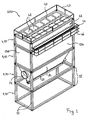
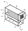
- a bag filter according to invention is globally indicated with reference numeral 100.
- the bag filter 100 comprises a plurality of functional modules 1-4 associated with each other and adapted to perform respective functions within the bag filter.
- the bag filter 100 comprises a support module 1, a dust collection module 2, a filtration module 3 and a collection module for the filtered gaseous substance or plenum 4, the features of which shall be better illustrated in the remainder.
- the functional modules 1-4 have a respective structure at least partially obtained from one or more freight containers, generically indicated with the reference numeral 10.
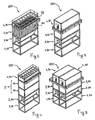
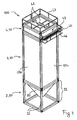
- FIGS 1-3, 5 , 7 , and 9 show embodiments of the bag filter 100 in which each functional module 1-4 has a respective structure entirely obtained from a respective freight container 10.
- each functional module 1-4 has a respective structure obtained from two or more freight containers 10, as in the case of the filtration module 3 of the embodiment shown in figure 4 , which is obtained from two freight containers 10.
- one or more functional modules 1-4 have a respective structure obtained from a same freight container 10.
- the freight containers 10 have a parallelepiped or cubic shape, comprising a plurality of frame members 11 assembled with each other by means of corner fittings 12, in such a way as to define a framework of the freight container, and a plurality of enclosure walls 13 arranged between the frame members 11 and forming an enclosure of the freight container.
- the enclosure walls 13 it is possible to functionally distinguish a base 13a, a roof 13b, a pair of opposing side walls 13c a front wall 13d, normally provided with an access to the freight container, and a rear wall 13e, opposed to the front wall 13d.
- the freight containers 10 are freight containers conforming to the ISO (International Organisation for Standardization) 1496 standard, i.e. freight containers having a framework with 12 frame members assembled with each other by means of corner fittings, which in turns conform to the ISO 1161 standard, and having characteristic dimensions (usually height and/or length) within predetermined ranges.
- ISO International Organisation for Standardization
- the freight containers 10 can be freight containers assimilable to the ISO 1496 standard, i.e. freight containers having a framework with 12 frame members assembled with each other by means of corner fittings, which in turn conform to the ISO 1161 standard, but having characteristic dimensions that do not conform to the ISO 1496 standard.
- the structures of the functional modules 1-4 comprise at least the frame members 11 and the corner fittings 12 of the freight container or containers 10 from which they are obtained.
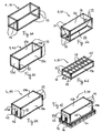
- Figures 6a-6f and 8a-8c show preferred embodiments of the functional modules 1-4 obtained from freight containers 10.
- the freight containers 10 employed to obtain the functional modules 1-4 in these examples conform to the ISO 1496-I-standard dimensional type 1C.
- figure 6a shows a support module 1a, the structure of which preferably consist of the framework a freight container 10, i.e. of only the frame members 11 and the corner fittings 12.
- a support module 1a the structure of which preferably consist of the framework a freight container 10, i.e. of only the frame members 11 and the corner fittings 12.
- one or more of the original enclosure walls 13 can be retained and/or reinforcing elements, such as, for example, bracing, stiffeners or ribs, can be added to increase the rigidity of the module.
- the support module 1 is usually employed at the base of the bag filter 100 ( figures 1-5 ), but can also be omitted ( figure 7 ), for example when pillars provided at the installation site are used.
- Figure 6b shows a dust collection module 2 with a collection hopper 20.
- the structure of this module is also based on the framework of a freight container 10.
- the collection hopper 20 has respective walls directly attached, by means of welding or mechanical fastening, to the frame members 11 defining the perimeter of a face of the freight container 10.
- a flange 21 is formed for connecting a inlet tubing of the gaseous substance (not shown).
- the collection hopper 20 is also preferably provided with extraction means 22 for the collected dust, in this case of the screw type.
- extraction means 22 can be used, all known to a man skilled in the art, such as for example drag conveyors, sluices valves of the single or double flap type or of the rotary type, fluidized conveyors, dust scrapers.
- FIG. 8c Another dust collection module 2, different in morphology but conceptually analogous to that of figure 6b , is shown in figure 8c .
- Figure 6c shows a filtration module 3 adapted to house a plurality of filtering bags 30, which are visible in detail in the views with partially removed parts of figure 2 and figure 9 .
- the structure of this module is obtained from a freight container 10 preferably by removing two enclosure walls 13 in order to provide a fluid communication to the functional modules 2 and 4 and, at the same time, to define a lateral enclosure for the filtering bags 30.
- the choice of the enclosure walls 13 to be removed is determined by the assembly mode of the functional modules 1-4 and/or by the arrangement of the filtering bags 30 inside the filtration module 3.
- the functional modules 1-4 are to be superimposed in a horizontal position (direction of superposition of the modules parallel to a transverse axis of the freight containers 10), and if the filtering bags 30 are arranged vertically in the filtration module 3 (longitudinal axes of the filtering bags parallel to the direction of superposition of the modules), as in the embodiments of the bag filter 100 shown in figures 1-5 , the base 13a and the roof 13b of the freight container 10 are removed ( figure 6c ).
- the functional modules 1-4 are to be superimposed in a vertical position (direction of superposition of the modules parallel to a longitudinal axis of the freight containers 10) and the filtering bags 30 are again arranged vertically in the filtration module 3, as in the embodiment of the bag filter 100 shown in figure 7 , the front wall 13d and the back wall 13e of the freight container 10 are removed ( figure 8a ).
- the functional modules 1-4 are to be superimposed in either horizontal or vertical position, but the filtration bags 30 are arranged horizontally inside the filtration module 3 (longitudinal axes of the filtering bags perpendicular to the direction of superposition of the modules), as in the embodiment of the bag filter 100 shown in figure 9 , two generic adjacent enclosure walls 13 of the freight container 10 are removed.
- the filtering bags 30 are normally connected to a suitable bag plate 31. If the bag plate 31 is associated with the filtration module 3, this is preferably directly attached, by means of mechanical fastening or welding, to the frame members 11 defining the perimeter of one of the faces of the freight container 10, after removal of the corresponding enclosure wall 13.
- Figures 6d-6f and 8a show different embodiments of a plenum 4.
- the structure of this module is obtained from a freight container 10 preferably by removing one or two opposing enclosure walls 13, in order to provide a fluid communication to the filtration module 3 and, if necessary, a suitable equipped wall for the inspection of or the access to the plenum 4. Also in this case, the choice of the enclosure walls 13 to be removed is determined by the assembly mode of the functional modules 1-4.
- figures 6d and 8a show a first embodiment of the plenum 4, in which the base 13a (not visible in the views of these figures) and the roof 13b of the freight container 10 are removed.
- an upper wall 40 is provided, equipped with one or more hatches 41 for the inspection of the plenum 4 and of the filtering bags 30, as well as for mounting or extracting the same.
- Figures 6e and 6f show another embodiment of the plenum 4, having dimensions suitable for allowing access of personnel inside it. Access takes place by means of an access door 42, either already existing in the freight container 10 or purposely created in one of the enclosure walls 13 of the same. In this case, only one of the enclosure walls 13, normally the base 13a, is removed, while other walls may be structurally modified for specific purposes.
- the bag plate 31 can be associated with this module, rather than with the filtration module 3. Also in this case, the bag plate 31 is preferably directly attached, by means of mechanical fastening or welding, to the frame members 11 defining the perimeter of one of the faces of the freight container 10 from which the corresponding enclosure wall 13 has been removed ( figures 6e and 6f ).
- the plenum 4 includes a compressed air distribution system 43, used for cleaning the filtering bags 30.
- the compressed air distribution system 43 typically comprises a collector to which a plurality of blowing pipes are connected and can be partially or wholly housed in the freight container 10 from which the plenum 4 is obtained.
- figure 6f shows an embodiment of the plenum 4 in which the compressed air distribution system 43 comprises a collector 44 external to the freight container 10, and internal blowing pipes 44 (not shown).
- the plenum 4 is preferably further provided with external gangways 46 and/or handrails 47, providing the necessary access thereto in conditions of safety ( figures 1-5 , 6f , 7 ). These components are preferably directly attached to the frame members 11 of the freight container 10 from which the plenum 4 is obtained.
- At one or more of the walls of the plenum 4 flanges are further provided for connecting discharge tubings of the filtered gaseous substance (again, not shown).
- the structure of the plenum 4 can be as well obtained from two or more freight containers 10.
- a covering module (not shown) can be optionally provided, adapted to define an at least partially closed environment at the upper wall of the bag filter 100, for allowing inspection and maintenance operations to be carried out whilst sheltered from the elements.
- Such module can be equipped with hoists for lifting loads.
- the structure of this additional functional module can be as well obtained at least partially from a freight container 10, in ways similar to those explained above with reference to the functional modules 1-4.
- Figure 5 shows an embodiment of the bag filter 100 in which two units, assembled with functional modules 1-4 described above, are arranged in parallel so as to treat a greater flux of gaseous substance.
- the method essentially comprises a first step of providing the functional modules 1-4 and a second step of suitably assembling these modules to obtain the bag filter 100.
- the provision of the modules can take place either in the workshop or at the site where the filter is to be installed.
- the assembly of the modules preferably takes place at the site where the filter is to be installed.
- the step of providing the functional modules 1-4 comprises a step of structurally modifying at least partially one or more freight containers 10 in such a way as to obtain the structure of one or more of such functional modules 1-4.
- the step of structurally modifying the freight containers 10 preferably comprises removing partially or totally, replacing or modifying at least one of the enclosure walls 13 thereof.
- the step of structurally modifying the freight containers 10 may comprise applying structural reinforcement elements, such as for example bracing, stiffeners or ribs, and/or coupling elements, such as for example coupling flanges, possibly provided with sealing elements, for the subsequent assembly in the bag filter 100.
- structural reinforcement elements such as for example bracing, stiffeners or ribs
- coupling elements such as for example coupling flanges, possibly provided with sealing elements
- the step of structurally modifying the freight containers 10 may further comprise the provision, internally and/or externally to the freight container 10, of auxiliary devices of the bag filter 100, such as, for example, compressed air distribution systems, ladders, gangways and/or hatches for access and inspection, handrails, lighting devices, control devices. Whenever possible, this auxiliary devices are preferably attached to frame members 11 of the freight containers 10.
- one or more functional modules 1-4 can be provided with thermal insulation, by applying pre-insulated walls in addition to or as a replacement for enclosure walls 13 of the respective freight containers 10, or by applying insulating material internally or externally thereto.
- the step of assembling with each other the functional modules 1-4 preferably comprises arranging these functional modules in series and/or in parallel with each other with respect to the direction of a filtration flow in the bag filter.
- the functional modules 1-4 are juxtaposed so that the corner fittings 12 of the respective freight containers 10 are in contact with each other.
- the step of assembling with each other the functional modules 1-4 comprises structurally securing the functional modules 1-4 to each other and airtight sealing joint portions between the functional modules 1-4.
- the structural securing is preferably obtained by means of mechanical fastening or welding at facing corner fittings 12.
- the airtight sealing is preferably obtained by welding at facing frame members 11 or by providing welded joint coverings and/or coupling flanges, welded or mechanically fastened, which may comprise gaskets.
Landscapes
- Chemical & Material Sciences (AREA)
- Chemical Kinetics & Catalysis (AREA)
- Filtering Of Dispersed Particles In Gases (AREA)
- Filtering Materials (AREA)
- Packages (AREA)
Claims (15)
- Beutelfilter (100), mit einer Vielzahl von Funktionseinheiten (1-4), die einander zugeordnet und dazu geeignet sind, jeweils Funktionen im Beutelfilter (100) auszuführen, dadurch gekennzeichnet, dass eine oder mehrere Funktionseinheiten (1-4) der Vielzahl von Funktionseinheiten jeweils eine Struktur aufweisen, die zumindest teilweise von einem oder mehreren Frachtcontainern (10) erhalten wird, wobei ein oder mehrere Frachtcontainer (10) eine quaderförmige oder kubische Struktur mit mehreren Rahmenelementen (11) aufweisen, die mit Eckbeschlägen (12) so zusammengebaut sind, dass sie einen Rahmen des Frachtcontainers definieren, und mit Umhüllungswänden (13), die so zwischen den Rahmenelementen angeordnet sind, dass sie eine Umhüllung des Frachtcontainers bilden, und wobei mindestens eine der mindestens einen Funktionseinheit (1-4) eine Filtereinheit (3) oder eine Auffangeinheit (4) für die gefilterte gasförmige Substanz ist, die eine Beutelplatte (31) zum Anschließen von Filterbeuteln aufweist, wobei die Beutelplatte (31) an den Rahmenelementen befestigt ist, die den Umfang einer Fläche eines Frachtcontainers des mindestens einen Frachtcontainers (10) definieren.
- Beutelfilter (100) nach Anspruch 1, bei dem die Umhüllungswand (13) der Fläche eines Frachtcontainers des mindestens einen Frachtcontainers (10) entfernt wurde.
- Beutelfilter (100) nach Anspruch 1 oder 2, bei dem jede Funktionseinheit der mindestens einen Funktionseinheit (1-4) jeweils eine Struktur aufweist, die zumindest teilweise von einem jeweiligen Frachtcontainer (10) erhalten wird.
- Beutelfilter (100) nach Anspruch 1, bei dem mindestens eine der einen oder mehreren Funktionseinheiten (1-4) jeweils eine Struktur aufweist, die zumindest teilweise von mindestens zwei Frachtcontainern (10) erhalten wird.
- Beutelfilter (100) nach Anspruch 1 oder 4, bei dem mindestens zwei der einen oder mehreren Funktionseinheiten (1-4) jeweils eine Struktur aufweisen, die zumindest teilweise von ein und demselben Frachtcontainer (10) erhalten wird.
- Beutelfilter (100) nach einem der vorhergehenden Ansprüche, bei dem ein oder mehrere Frachtcontainer (10) Frachtcontainer sind, die dem ISO 1496-Standard entsprechen oder damit vereinbar sind.
- Beutelfilter (100) nach einem der vorhergehenden Ansprüche, bei dem die jeweiligen Strukturen der einen oder mehreren Funktionseinheiten (1-4) die Rahmenelemente (11) und die Eckbeschläge (12) und optional mindestens eine der Umhüllungswände (13) aufweisen.
- Beutelfilter (100) nach einem der vorhergehenden Ansprüche, bei dem die Funktionseinheiten der Vielzahl von Funktionseinheiten (1-4) aus der Gruppe ausgewählt sind, die folgendes umfasst: Stützeinheiten (1), Staubauffangeinheiten (2), Filtereinheiten (3), Auffangeinheiten (4) für die gefilterte gasförmige Substanz.
- Beutelfilter (100) nach einem der vorhergehenden Ansprüche, bei dem mindestens eine der einen oder mehreren Funktionseinheiten (1-4) eine Staubauffangeinheit (2) mit einem Staubtrichter (20) ist und der Staubtrichter Wände aufweist, die jeweils an Rahmenelemente (11) befestigt sind, die den Umfang einer Fläche eines Frachtcontainers des mindestens einen Frachtcontainers (10) definieren.
- Beutelfilter (100) nach einem der vorhergehenden Ansprüche, bei dem mindestens eine der einen oder mehreren Funktionseinheiten (1-4) eine Auffangeinheit (4) für die gefilterte gasförmige Substanz mit einem Druckluftverteilungssystem (43) ist, wobei das Druckluftverteilungssystem (43) teilweise oder vollständig in einem Frachtcontainer des mindestens einen Frachtcontainers (10) untergebracht oder extern diesem zugeordnet ist.
- Verfahren zum Herstellen eines Beutelfilters (100), mit einer Vielzahl von Funktionseinheiten (1-4), die einander zugeordnet und dazu geeignet sind, jeweils Funktionen im Beutelfilter (100) auszuführen, wobei das Verfahren folgende Schritte umfasst:- Bereitstellen der Vielzahl von Funktionseinheiten (1-4) des Beutelfilters und- Zusammenbauen der bereitgestellten Funktionseinheiten (1-4),dadurch gekennzeichnet, dass der Schritt des Bereitstellens der Vielzahl von Funktionseinheiten (1-4) einen Schritt umfasst, bei dem:- ein oder mehrere Frachtcontainer (10) zumindest teilweise strukturell so verändert werden, dass die Struktur einer oder mehrerer Funktionseinheiten der Vielzahl von Funktionseinheiten (1-4) erhalten wird,wobei der oder die mehreren Frachtcontainer (10) eine im Wesentlichen quaderförmige Struktur mit mehreren Rahmenelementen (11) aufweisen, die mit Eckbeschlägen (12) so zusammengebaut sind, dass sie den Rahmen des Frachtcontainers definieren, und mit Umhüllungswänden (13), die so zwischen den Rahmenelementen angeordnet sind, dass sie eine Umhüllung des Frachtcontainers bilden, und wobei mindestens eine der mindestens einen Funktionseinheiten (1-4) eine Filtereinheit (3) oder eine Auffangeinheit (4) für die gefilterte gasförmige Substanz ist, die eine Beutelplatte (31) zum Anschließen von Filterbeutein aufweist, wobei der Schritt, bei dem einer oder mehrere der Frachtcontainer (10) zumindest teilweise strukturell verändert werden, das teilweise oder vollständige Entfernen, das Ersetzen oder Verändern mindestens einer der Umhüllungswände (13) und das Befestigen der Beutelplatte (31) an den Rahmenelementen umfasst, die den Umfang einer Fläche eines Frachtcontainers des mindestens einen Frachtcontainers (10) definieren.
- Verfahren nach Anspruch 11, bei dem der Schritt, bei dem einer oder mehrere der Frachtcontainer (10) zumindest teilweise strukturell verändert werden, ferner das Entfernen der Umhüllungswand (13) der Fläche eines Frachtcontainers des mindestens einen Frachtcontainers (10) umfasst, bevor die Beutelplatte (31) an den Rahmenelementen befestigt wird.
- Verfahren nach Anspruch 11 oder 12, bei dem der Schritt, bei dem einer oder mehrere der Frachtcontainer (10) zumindest teilweise strukturell verändert werden, das teilweise oder vollständige Entfernen, das Ersetzen oder Verändern mindestens einer der Umhüllungswände (13) und optional das Aufbringen von strukturellen Verstärkungselementen und/oder Verbindungselementen umfasst.
- Verfahren nach einem der Ansprüche 11 bis 13, bei dem der Schritt des Zusammenbauens der bereitgestellten Funktionseinheiten (1-4) den Schritt umfasst, bei dem:- die Funktionseinheiten (1-4) bezüglich der Richtung eines Filtrationsstroms im Beutelfilter in Reihe und/oder parallel zueinander geschaltet werden.
- Verfahren nach Anspruch 14, bei dem der Schritt des Zusammenbauens der bereitgestellten Funktionseinheiten (1-4) ferner den Schritt umfasst, bei dem:- die Funktionseinheiten (1-4) strukturell aneinander befestigt werden und- Verbindungsabschnitte zwischen den Funktionseinheiten (1-4) luftdicht versiegelt werden.
Applications Claiming Priority (2)
| Application Number | Priority Date | Filing Date | Title |
|---|---|---|---|
| IT001880A ITMI20071880A1 (it) | 2007-10-02 | 2007-10-02 | Filtro a maniche per la depurazione di aeriformi realizzato con struttura modulare basata sulla composizione di elementi derivati da container da carico o ad essi assimilabili |
| PCT/IB2008/002609 WO2009044265A2 (en) | 2007-10-02 | 2008-10-02 | Bag filter and method for its construction |
Publications (2)
| Publication Number | Publication Date |
|---|---|
| EP2114548A2 EP2114548A2 (de) | 2009-11-11 |
| EP2114548B1 true EP2114548B1 (de) | 2011-02-09 |
Family
ID=40313754
Family Applications (1)
| Application Number | Title | Priority Date | Filing Date |
|---|---|---|---|
| EP08835672A Not-in-force EP2114548B1 (de) | 2007-10-02 | 2008-10-02 | Beutelfilter und verfahren für seine herstellung |
Country Status (7)
| Country | Link |
|---|---|
| US (1) | US20100218469A1 (de) |
| EP (1) | EP2114548B1 (de) |
| AT (1) | ATE497822T1 (de) |
| DE (1) | DE602008004886D1 (de) |
| ES (1) | ES2363687T3 (de) |
| IT (1) | ITMI20071880A1 (de) |
| WO (1) | WO2009044265A2 (de) |
Families Citing this family (18)
| Publication number | Priority date | Publication date | Assignee | Title |
|---|---|---|---|---|
| US20130255359A1 (en) * | 2012-03-29 | 2013-10-03 | General Electric Company | Containerized mobile gas turbine filter test facility |
| FI123834B (en) | 2012-06-26 | 2013-11-15 | Outotec Oyj | Method of making a trough and trough |
| FI124674B (en) | 2012-06-26 | 2014-11-28 | Outotec Oyj | Solvent extraction method and solvent extraction basin |
| FI123803B (en) * | 2012-06-26 | 2013-10-31 | Outotec Oyj | A method for preparing a solvent extraction basin and a solvent extraction basin |
| FI123835B (en) | 2012-06-26 | 2013-11-15 | Outotec Oyj | Arrangement for a pool for solvent extraction |
| FI124030B (en) | 2012-06-26 | 2014-02-14 | Outotec Oyj | Method for making a fence and a fence |
| FI123831B (en) | 2012-06-26 | 2013-11-15 | Outotec Oyj | Solvent extraction clarifier tank arrangement |
| US8986411B2 (en) * | 2013-01-24 | 2015-03-24 | Clyde Bergemann Power Group Americas Inc. | Modular pulse jet fabric filter |
| GB201307265D0 (en) * | 2013-04-23 | 2013-05-29 | Scaife Martin | Modular compact hi-performance singular sku filtration device with common "Plug & Play" interface architecture capable of docking with fan, material handling |
| WO2014185901A1 (en) * | 2013-05-15 | 2014-11-20 | M-I L.L.C. | Modular waste processing system |
| US10850220B2 (en) * | 2015-08-24 | 2020-12-01 | Ingersoll-Rand Industrial U.S., Inc. | Modular inlet filter for a compressor system |
| CN105423437A (zh) * | 2015-12-15 | 2016-03-23 | 桐城市神墩环卫保洁有限公司 | 一种环保用空气净化装置 |
| CN105423436A (zh) * | 2015-12-15 | 2016-03-23 | 桐城市神墩环卫保洁有限公司 | 一种环卫保洁用空气净化器 |
| CN105546634A (zh) * | 2015-12-15 | 2016-05-04 | 桐城市神墩环卫保洁有限公司 | 一种环卫保洁用空气过滤箱 |
| CN106039857A (zh) * | 2016-08-01 | 2016-10-26 | 安双志 | 一种建筑工地用高效的除尘装置 |
| CN115253410A (zh) * | 2017-02-22 | 2022-11-01 | 过滤技术公司 | 矩形过滤器、组件及其过滤方法 |
| AU2019229103B2 (en) | 2018-03-02 | 2023-12-07 | Modular Plant Solutions Llc | Modular process plant structural system |
| CN109316850A (zh) * | 2018-10-26 | 2019-02-12 | 浙江鸿盛环保科技集团有限公司 | 模块化除尘器系统及其控制方法 |
Family Cites Families (19)
| Publication number | Priority date | Publication date | Assignee | Title |
|---|---|---|---|---|
| US3870489A (en) * | 1972-10-13 | 1975-03-11 | Myers Sherman Co | Air filter systems for debris collecting apparatus |
| US4227893A (en) * | 1978-09-01 | 1980-10-14 | Peabody-Myers Corporation | Mobile vacuum loader |
| US4264345A (en) * | 1979-09-12 | 1981-04-28 | American Air Filter Company, Inc. | Filter housing |
| US4383840A (en) * | 1981-10-28 | 1983-05-17 | Jones Donald W | Dust collector with tubular bag and cage filters and beater rods |
| US4578840A (en) * | 1984-06-04 | 1986-04-01 | General Resource Corp. | Mobile vacuum machine |
| US4822430A (en) * | 1985-08-22 | 1989-04-18 | Carberry Victor V | Method and apparatus for cleaning boiler burners |
| US5030259B1 (en) * | 1989-12-18 | 1994-04-05 | Guzzler Mgf Inc | Portable vacuum cleaning system |
| US5588985A (en) * | 1990-11-14 | 1996-12-31 | Abatement Technologies, Inc. | Methods of using a portable filtration unit |
| US5069691B2 (en) * | 1990-11-14 | 1996-11-05 | Abatement Technologies | Portable filtration unit |
| US5433763A (en) * | 1990-11-14 | 1995-07-18 | Abatement Technologies | Portable filtration unit |
| US5593470A (en) * | 1990-11-14 | 1997-01-14 | Abatement Technologies, Inc. | Portable filtration unit |
| US5438729A (en) * | 1992-12-28 | 1995-08-08 | Powell; Samuel O. | Apparatus for cleaning air ducts |
| US5762664A (en) * | 1996-12-18 | 1998-06-09 | National Tool And Equipment, Inc. | Mobile vessel for removal of noxious fumes |
| GB9919965D0 (en) * | 1999-08-23 | 1999-10-27 | Boc Group Plc | Adsorption apparatus |
| DE10146954A1 (de) * | 2001-09-24 | 2003-05-15 | Rotring Engineering Gmbh | Luftfiltersystem |
| GB0224760D0 (en) * | 2002-10-25 | 2002-12-04 | Jowett E C | Waste water treatment station in shipping container |
| US20050274094A1 (en) * | 2003-03-17 | 2005-12-15 | Demarco Thomas M | Vacuum loader |
| US7479170B1 (en) * | 2004-09-01 | 2009-01-20 | Collette Jerry R | Modular up-draft pressure pulse bag house |
| US7806948B2 (en) * | 2006-11-14 | 2010-10-05 | Johnson Crushers International | Filter system for internal combustion engines operated in a contaminated atmosphere |
-
2007
- 2007-10-02 IT IT001880A patent/ITMI20071880A1/it unknown
-
2008
- 2008-10-02 DE DE602008004886T patent/DE602008004886D1/de active Active
- 2008-10-02 AT AT08835672T patent/ATE497822T1/de not_active IP Right Cessation
- 2008-10-02 ES ES08835672T patent/ES2363687T3/es active Active
- 2008-10-02 EP EP08835672A patent/EP2114548B1/de not_active Not-in-force
- 2008-10-02 WO PCT/IB2008/002609 patent/WO2009044265A2/en not_active Ceased
- 2008-10-02 US US12/681,099 patent/US20100218469A1/en not_active Abandoned
Also Published As
| Publication number | Publication date |
|---|---|
| WO2009044265A2 (en) | 2009-04-09 |
| ITMI20071880A1 (it) | 2009-04-03 |
| WO2009044265A3 (en) | 2009-08-06 |
| US20100218469A1 (en) | 2010-09-02 |
| ES2363687T3 (es) | 2011-08-11 |
| ATE497822T1 (de) | 2011-02-15 |
| EP2114548A2 (de) | 2009-11-11 |
| DE602008004886D1 (de) | 2011-03-24 |
Similar Documents
| Publication | Publication Date | Title |
|---|---|---|
| US20100218469A1 (en) | Bag filter and method for its construction | |
| EP3302757B1 (de) | Modulares reinigungssystem für staub in der luft | |
| CA1175755A (en) | Compact dust filter assembly | |
| US9901858B2 (en) | Modular cleaner for airborne dust with detachable bin | |
| US3876402A (en) | Apparatus for separating particulate matter from a gas stream | |
| RU2479338C1 (ru) | Фильтр рукавно-картриджный для очистки воздуха от механических примесей | |
| EP2408535B1 (de) | Filtervorrichtung zur reinigung eines mit partikeln beladenen luftstroms | |
| CN210045556U (zh) | 一种振动筛 | |
| US11946269B2 (en) | Modular integrated system modules | |
| CN104180506A (zh) | 高效节能空调机组模块式快装过滤器 | |
| JPH0322146B2 (de) | ||
| CN220257504U (zh) | 一种四合一过滤器 | |
| US20250052054A1 (en) | Modular, integrated system modules | |
| CN1009334B (zh) | 空气净化器 | |
| US12029378B2 (en) | Vacuum collection vehicle | |
| CN203577519U (zh) | 滤筒除尘器 | |
| JP3728649B2 (ja) | 吸着剤モジュールのシール装置 | |
| CN2661654Y (zh) | 环保型粉尘物料收集器 | |
| CN103055616A (zh) | 模块组合袋式除尘器及其装运方法 | |
| CN209081451U (zh) | 一种水处理设备智能气源储存分配应用装置 | |
| CN217662189U (zh) | 雾状液体回收结构及系统 | |
| CN210495581U (zh) | 一种拼装式布袋除尘器 | |
| CN221309880U (zh) | 一种布袋除尘器 | |
| CN220736834U (zh) | 一种粉尘过滤装置 | |
| CN219333502U (zh) | 袋式集尘设备 |
Legal Events
| Date | Code | Title | Description |
|---|---|---|---|
| PUAI | Public reference made under article 153(3) epc to a published international application that has entered the european phase |
Free format text: ORIGINAL CODE: 0009012 |
|
| 17P | Request for examination filed |
Effective date: 20090825 |
|
| AK | Designated contracting states |
Kind code of ref document: A2 Designated state(s): AT BE BG CH CY CZ DE DK EE ES FI FR GB GR HR HU IE IS IT LI LT LU LV MC MT NL NO PL PT RO SE SI SK TR |
|
| 17Q | First examination report despatched |
Effective date: 20091119 |
|
| GRAP | Despatch of communication of intention to grant a patent |
Free format text: ORIGINAL CODE: EPIDOSNIGR1 |
|
| GRAS | Grant fee paid |
Free format text: ORIGINAL CODE: EPIDOSNIGR3 |
|
| GRAA | (expected) grant |
Free format text: ORIGINAL CODE: 0009210 |
|
| AK | Designated contracting states |
Kind code of ref document: B1 Designated state(s): AT BE BG CH CY CZ DE DK EE ES FI FR GB GR HR HU IE IS IT LI LT LU LV MC MT NL NO PL PT RO SE SI SK TR |
|
| REG | Reference to a national code |
Ref country code: GB Ref legal event code: FG4D |
|
| REG | Reference to a national code |
Ref country code: CH Ref legal event code: EP |
|
| REG | Reference to a national code |
Ref country code: IE Ref legal event code: FG4D |
|
| REF | Corresponds to: |
Ref document number: 602008004886 Country of ref document: DE Date of ref document: 20110324 Kind code of ref document: P |
|
| REG | Reference to a national code |
Ref country code: DE Ref legal event code: R096 Ref document number: 602008004886 Country of ref document: DE Effective date: 20110324 |
|
| REG | Reference to a national code |
Ref country code: NL Ref legal event code: VDEP Effective date: 20110209 |
|
| LTIE | Lt: invalidation of european patent or patent extension |
Effective date: 20110209 |
|
| PG25 | Lapsed in a contracting state [announced via postgrant information from national office to epo] |
Ref country code: SE Free format text: LAPSE BECAUSE OF FAILURE TO SUBMIT A TRANSLATION OF THE DESCRIPTION OR TO PAY THE FEE WITHIN THE PRESCRIBED TIME-LIMIT Effective date: 20110209 Ref country code: PT Free format text: LAPSE BECAUSE OF FAILURE TO SUBMIT A TRANSLATION OF THE DESCRIPTION OR TO PAY THE FEE WITHIN THE PRESCRIBED TIME-LIMIT Effective date: 20110609 Ref country code: GR Free format text: LAPSE BECAUSE OF FAILURE TO SUBMIT A TRANSLATION OF THE DESCRIPTION OR TO PAY THE FEE WITHIN THE PRESCRIBED TIME-LIMIT Effective date: 20110510 Ref country code: HR Free format text: LAPSE BECAUSE OF FAILURE TO SUBMIT A TRANSLATION OF THE DESCRIPTION OR TO PAY THE FEE WITHIN THE PRESCRIBED TIME-LIMIT Effective date: 20110209 Ref country code: LT Free format text: LAPSE BECAUSE OF FAILURE TO SUBMIT A TRANSLATION OF THE DESCRIPTION OR TO PAY THE FEE WITHIN THE PRESCRIBED TIME-LIMIT Effective date: 20110209 Ref country code: LV Free format text: LAPSE BECAUSE OF FAILURE TO SUBMIT A TRANSLATION OF THE DESCRIPTION OR TO PAY THE FEE WITHIN THE PRESCRIBED TIME-LIMIT Effective date: 20110209 Ref country code: NO Free format text: LAPSE BECAUSE OF FAILURE TO SUBMIT A TRANSLATION OF THE DESCRIPTION OR TO PAY THE FEE WITHIN THE PRESCRIBED TIME-LIMIT Effective date: 20110509 |
|
| REG | Reference to a national code |
Ref country code: ES Ref legal event code: FG2A Ref document number: 2363687 Country of ref document: ES Kind code of ref document: T3 Effective date: 20110811 |
|
| PG25 | Lapsed in a contracting state [announced via postgrant information from national office to epo] |
Ref country code: FI Free format text: LAPSE BECAUSE OF FAILURE TO SUBMIT A TRANSLATION OF THE DESCRIPTION OR TO PAY THE FEE WITHIN THE PRESCRIBED TIME-LIMIT Effective date: 20110209 Ref country code: BG Free format text: LAPSE BECAUSE OF FAILURE TO SUBMIT A TRANSLATION OF THE DESCRIPTION OR TO PAY THE FEE WITHIN THE PRESCRIBED TIME-LIMIT Effective date: 20110509 Ref country code: CY Free format text: LAPSE BECAUSE OF FAILURE TO SUBMIT A TRANSLATION OF THE DESCRIPTION OR TO PAY THE FEE WITHIN THE PRESCRIBED TIME-LIMIT Effective date: 20110209 Ref country code: AT Free format text: LAPSE BECAUSE OF FAILURE TO SUBMIT A TRANSLATION OF THE DESCRIPTION OR TO PAY THE FEE WITHIN THE PRESCRIBED TIME-LIMIT Effective date: 20110209 Ref country code: PL Free format text: LAPSE BECAUSE OF FAILURE TO SUBMIT A TRANSLATION OF THE DESCRIPTION OR TO PAY THE FEE WITHIN THE PRESCRIBED TIME-LIMIT Effective date: 20110209 Ref country code: BE Free format text: LAPSE BECAUSE OF FAILURE TO SUBMIT A TRANSLATION OF THE DESCRIPTION OR TO PAY THE FEE WITHIN THE PRESCRIBED TIME-LIMIT Effective date: 20110209 Ref country code: NL Free format text: LAPSE BECAUSE OF FAILURE TO SUBMIT A TRANSLATION OF THE DESCRIPTION OR TO PAY THE FEE WITHIN THE PRESCRIBED TIME-LIMIT Effective date: 20110209 Ref country code: SI Free format text: LAPSE BECAUSE OF FAILURE TO SUBMIT A TRANSLATION OF THE DESCRIPTION OR TO PAY THE FEE WITHIN THE PRESCRIBED TIME-LIMIT Effective date: 20110209 |
|
| PG25 | Lapsed in a contracting state [announced via postgrant information from national office to epo] |
Ref country code: EE Free format text: LAPSE BECAUSE OF FAILURE TO SUBMIT A TRANSLATION OF THE DESCRIPTION OR TO PAY THE FEE WITHIN THE PRESCRIBED TIME-LIMIT Effective date: 20110209 Ref country code: DK Free format text: LAPSE BECAUSE OF FAILURE TO SUBMIT A TRANSLATION OF THE DESCRIPTION OR TO PAY THE FEE WITHIN THE PRESCRIBED TIME-LIMIT Effective date: 20110209 |
|
| PG25 | Lapsed in a contracting state [announced via postgrant information from national office to epo] |
Ref country code: SK Free format text: LAPSE BECAUSE OF FAILURE TO SUBMIT A TRANSLATION OF THE DESCRIPTION OR TO PAY THE FEE WITHIN THE PRESCRIBED TIME-LIMIT Effective date: 20110209 Ref country code: RO Free format text: LAPSE BECAUSE OF FAILURE TO SUBMIT A TRANSLATION OF THE DESCRIPTION OR TO PAY THE FEE WITHIN THE PRESCRIBED TIME-LIMIT Effective date: 20110209 Ref country code: CZ Free format text: LAPSE BECAUSE OF FAILURE TO SUBMIT A TRANSLATION OF THE DESCRIPTION OR TO PAY THE FEE WITHIN THE PRESCRIBED TIME-LIMIT Effective date: 20110209 |
|
| PLBE | No opposition filed within time limit |
Free format text: ORIGINAL CODE: 0009261 |
|
| STAA | Information on the status of an ep patent application or granted ep patent |
Free format text: STATUS: NO OPPOSITION FILED WITHIN TIME LIMIT |
|
| 26N | No opposition filed |
Effective date: 20111110 |
|
| REG | Reference to a national code |
Ref country code: DE Ref legal event code: R097 Ref document number: 602008004886 Country of ref document: DE Effective date: 20111110 |
|
| PG25 | Lapsed in a contracting state [announced via postgrant information from national office to epo] |
Ref country code: MC Free format text: LAPSE BECAUSE OF NON-PAYMENT OF DUE FEES Effective date: 20111031 |
|
| REG | Reference to a national code |
Ref country code: IE Ref legal event code: MM4A |
|
| PG25 | Lapsed in a contracting state [announced via postgrant information from national office to epo] |
Ref country code: IE Free format text: LAPSE BECAUSE OF NON-PAYMENT OF DUE FEES Effective date: 20111002 |
|
| PG25 | Lapsed in a contracting state [announced via postgrant information from national office to epo] |
Ref country code: MT Free format text: LAPSE BECAUSE OF FAILURE TO SUBMIT A TRANSLATION OF THE DESCRIPTION OR TO PAY THE FEE WITHIN THE PRESCRIBED TIME-LIMIT Effective date: 20110209 |
|
| PG25 | Lapsed in a contracting state [announced via postgrant information from national office to epo] |
Ref country code: LU Free format text: LAPSE BECAUSE OF NON-PAYMENT OF DUE FEES Effective date: 20111002 |
|
| REG | Reference to a national code |
Ref country code: CH Ref legal event code: PL |
|
| PG25 | Lapsed in a contracting state [announced via postgrant information from national office to epo] |
Ref country code: LI Free format text: LAPSE BECAUSE OF NON-PAYMENT OF DUE FEES Effective date: 20121031 Ref country code: CH Free format text: LAPSE BECAUSE OF NON-PAYMENT OF DUE FEES Effective date: 20121031 Ref country code: IS Free format text: LAPSE BECAUSE OF FAILURE TO SUBMIT A TRANSLATION OF THE DESCRIPTION OR TO PAY THE FEE WITHIN THE PRESCRIBED TIME-LIMIT Effective date: 20110209 |
|
| PG25 | Lapsed in a contracting state [announced via postgrant information from national office to epo] |
Ref country code: TR Free format text: LAPSE BECAUSE OF FAILURE TO SUBMIT A TRANSLATION OF THE DESCRIPTION OR TO PAY THE FEE WITHIN THE PRESCRIBED TIME-LIMIT Effective date: 20110209 |
|
| PG25 | Lapsed in a contracting state [announced via postgrant information from national office to epo] |
Ref country code: HU Free format text: LAPSE BECAUSE OF FAILURE TO SUBMIT A TRANSLATION OF THE DESCRIPTION OR TO PAY THE FEE WITHIN THE PRESCRIBED TIME-LIMIT Effective date: 20110209 |
|
| PGFP | Annual fee paid to national office [announced via postgrant information from national office to epo] |
Ref country code: GB Payment date: 20131028 Year of fee payment: 6 |
|
| PGFP | Annual fee paid to national office [announced via postgrant information from national office to epo] |
Ref country code: DE Payment date: 20141128 Year of fee payment: 7 Ref country code: ES Payment date: 20141126 Year of fee payment: 7 Ref country code: FR Payment date: 20141118 Year of fee payment: 7 |
|
| PGFP | Annual fee paid to national office [announced via postgrant information from national office to epo] |
Ref country code: IT Payment date: 20141031 Year of fee payment: 7 |
|
| GBPC | Gb: european patent ceased through non-payment of renewal fee |
Effective date: 20141002 |
|
| PG25 | Lapsed in a contracting state [announced via postgrant information from national office to epo] |
Ref country code: GB Free format text: LAPSE BECAUSE OF NON-PAYMENT OF DUE FEES Effective date: 20141002 |
|
| REG | Reference to a national code |
Ref country code: DE Ref legal event code: R119 Ref document number: 602008004886 Country of ref document: DE |
|
| PG25 | Lapsed in a contracting state [announced via postgrant information from national office to epo] |
Ref country code: DE Free format text: LAPSE BECAUSE OF NON-PAYMENT OF DUE FEES Effective date: 20160503 Ref country code: IT Free format text: LAPSE BECAUSE OF NON-PAYMENT OF DUE FEES Effective date: 20151002 |
|
| REG | Reference to a national code |
Ref country code: FR Ref legal event code: ST Effective date: 20160630 |
|
| PG25 | Lapsed in a contracting state [announced via postgrant information from national office to epo] |
Ref country code: FR Free format text: LAPSE BECAUSE OF NON-PAYMENT OF DUE FEES Effective date: 20151102 |
|
| REG | Reference to a national code |
Ref country code: ES Ref legal event code: FD2A Effective date: 20161125 |
|
| PG25 | Lapsed in a contracting state [announced via postgrant information from national office to epo] |
Ref country code: ES Free format text: LAPSE BECAUSE OF NON-PAYMENT OF DUE FEES Effective date: 20151003 |