EP2114659B1 - Füllkörper - Google Patents
Füllkörper Download PDFInfo
- Publication number
- EP2114659B1 EP2114659B1 EP07847045A EP07847045A EP2114659B1 EP 2114659 B1 EP2114659 B1 EP 2114659B1 EP 07847045 A EP07847045 A EP 07847045A EP 07847045 A EP07847045 A EP 07847045A EP 2114659 B1 EP2114659 B1 EP 2114659B1
- Authority
- EP
- European Patent Office
- Prior art keywords
- plastic sheets
- plastic
- contact body
- connection elements
- pairs
- Prior art date
- Legal status (The legal status is an assumption and is not a legal conclusion. Google has not performed a legal analysis and makes no representation as to the accuracy of the status listed.)
- Not-in-force
Links
Images




Classifications
-
- F—MECHANICAL ENGINEERING; LIGHTING; HEATING; WEAPONS; BLASTING
- F28—HEAT EXCHANGE IN GENERAL
- F28F—DETAILS OF HEAT-EXCHANGE AND HEAT-TRANSFER APPARATUS, OF GENERAL APPLICATION
- F28F25/00—Component parts of trickle coolers
- F28F25/02—Component parts of trickle coolers for distributing, circulating, and accumulating liquid
- F28F25/08—Splashing boards or grids, e.g. for converting liquid sprays into liquid films; Elements or beds for increasing the area of the contact surface
- F28F25/087—Vertical or inclined sheets; Supports or spacers
-
- B—PERFORMING OPERATIONS; TRANSPORTING
- B01—PHYSICAL OR CHEMICAL PROCESSES OR APPARATUS IN GENERAL
- B01J—CHEMICAL OR PHYSICAL PROCESSES, e.g. CATALYSIS OR COLLOID CHEMISTRY; THEIR RELEVANT APPARATUS
- B01J19/00—Chemical, physical or physico-chemical processes in general; Their relevant apparatus
- B01J19/32—Packing elements in the form of grids or built-up elements for forming a unit or module inside the apparatus for mass or heat transfer
-
- B—PERFORMING OPERATIONS; TRANSPORTING
- B29—WORKING OF PLASTICS; WORKING OF SUBSTANCES IN A PLASTIC STATE IN GENERAL
- B29C—SHAPING OR JOINING OF PLASTICS; SHAPING OF MATERIAL IN A PLASTIC STATE, NOT OTHERWISE PROVIDED FOR; AFTER-TREATMENT OF THE SHAPED PRODUCTS, e.g. REPAIRING
- B29C65/00—Joining or sealing of preformed parts, e.g. welding of plastics materials; Apparatus therefor
- B29C65/56—Joining or sealing of preformed parts, e.g. welding of plastics materials; Apparatus therefor using mechanical means or mechanical connections, e.g. form-fits
-
- B—PERFORMING OPERATIONS; TRANSPORTING
- B29—WORKING OF PLASTICS; WORKING OF SUBSTANCES IN A PLASTIC STATE IN GENERAL
- B29C—SHAPING OR JOINING OF PLASTICS; SHAPING OF MATERIAL IN A PLASTIC STATE, NOT OTHERWISE PROVIDED FOR; AFTER-TREATMENT OF THE SHAPED PRODUCTS, e.g. REPAIRING
- B29C65/00—Joining or sealing of preformed parts, e.g. welding of plastics materials; Apparatus therefor
- B29C65/56—Joining or sealing of preformed parts, e.g. welding of plastics materials; Apparatus therefor using mechanical means or mechanical connections, e.g. form-fits
- B29C65/60—Riveting or staking
- B29C65/606—Riveting or staking the rivets being integral with one of the parts to be joined, i.e. staking
- B29C65/607—Riveting or staking the rivets being integral with one of the parts to be joined, i.e. staking the integral rivets being hollow
-
- B—PERFORMING OPERATIONS; TRANSPORTING
- B29—WORKING OF PLASTICS; WORKING OF SUBSTANCES IN A PLASTIC STATE IN GENERAL
- B29C—SHAPING OR JOINING OF PLASTICS; SHAPING OF MATERIAL IN A PLASTIC STATE, NOT OTHERWISE PROVIDED FOR; AFTER-TREATMENT OF THE SHAPED PRODUCTS, e.g. REPAIRING
- B29C66/00—General aspects of processes or apparatus for joining preformed parts
- B29C66/01—General aspects dealing with the joint area or with the area to be joined
- B29C66/05—Particular design of joint configurations
- B29C66/10—Particular design of joint configurations particular design of the joint cross-sections
- B29C66/11—Joint cross-sections comprising a single joint-segment, i.e. one of the parts to be joined comprising a single joint-segment in the joint cross-section
- B29C66/112—Single lapped joints
- B29C66/1122—Single lap to lap joints, i.e. overlap joints
-
- B—PERFORMING OPERATIONS; TRANSPORTING
- B29—WORKING OF PLASTICS; WORKING OF SUBSTANCES IN A PLASTIC STATE IN GENERAL
- B29C—SHAPING OR JOINING OF PLASTICS; SHAPING OF MATERIAL IN A PLASTIC STATE, NOT OTHERWISE PROVIDED FOR; AFTER-TREATMENT OF THE SHAPED PRODUCTS, e.g. REPAIRING
- B29C66/00—General aspects of processes or apparatus for joining preformed parts
- B29C66/01—General aspects dealing with the joint area or with the area to be joined
- B29C66/05—Particular design of joint configurations
- B29C66/10—Particular design of joint configurations particular design of the joint cross-sections
- B29C66/13—Single flanged joints; Fin-type joints; Single hem joints; Edge joints; Interpenetrating fingered joints; Other specific particular designs of joint cross-sections not provided for in groups B29C66/11 - B29C66/12
- B29C66/131—Single flanged joints, i.e. one of the parts to be joined being rigid and flanged in the joint area
- B29C66/1312—Single flange to flange joints, the parts to be joined being rigid
-
- B—PERFORMING OPERATIONS; TRANSPORTING
- B29—WORKING OF PLASTICS; WORKING OF SUBSTANCES IN A PLASTIC STATE IN GENERAL
- B29C—SHAPING OR JOINING OF PLASTICS; SHAPING OF MATERIAL IN A PLASTIC STATE, NOT OTHERWISE PROVIDED FOR; AFTER-TREATMENT OF THE SHAPED PRODUCTS, e.g. REPAIRING
- B29C66/00—General aspects of processes or apparatus for joining preformed parts
- B29C66/01—General aspects dealing with the joint area or with the area to be joined
- B29C66/05—Particular design of joint configurations
- B29C66/20—Particular design of joint configurations particular design of the joint lines, e.g. of the weld lines
- B29C66/21—Particular design of joint configurations particular design of the joint lines, e.g. of the weld lines said joint lines being formed by a single dot or dash or by several dots or dashes, i.e. spot joining or spot welding
-
- B—PERFORMING OPERATIONS; TRANSPORTING
- B29—WORKING OF PLASTICS; WORKING OF SUBSTANCES IN A PLASTIC STATE IN GENERAL
- B29C—SHAPING OR JOINING OF PLASTICS; SHAPING OF MATERIAL IN A PLASTIC STATE, NOT OTHERWISE PROVIDED FOR; AFTER-TREATMENT OF THE SHAPED PRODUCTS, e.g. REPAIRING
- B29C66/00—General aspects of processes or apparatus for joining preformed parts
- B29C66/40—General aspects of joining substantially flat articles, e.g. plates, sheets or web-like materials; Making flat seams in tubular or hollow articles; Joining single elements to substantially flat surfaces
- B29C66/41—Joining substantially flat articles ; Making flat seams in tubular or hollow articles
- B29C66/43—Joining a relatively small portion of the surface of said articles
-
- B—PERFORMING OPERATIONS; TRANSPORTING
- B29—WORKING OF PLASTICS; WORKING OF SUBSTANCES IN A PLASTIC STATE IN GENERAL
- B29C—SHAPING OR JOINING OF PLASTICS; SHAPING OF MATERIAL IN A PLASTIC STATE, NOT OTHERWISE PROVIDED FOR; AFTER-TREATMENT OF THE SHAPED PRODUCTS, e.g. REPAIRING
- B29C66/00—General aspects of processes or apparatus for joining preformed parts
- B29C66/40—General aspects of joining substantially flat articles, e.g. plates, sheets or web-like materials; Making flat seams in tubular or hollow articles; Joining single elements to substantially flat surfaces
- B29C66/41—Joining substantially flat articles ; Making flat seams in tubular or hollow articles
- B29C66/43—Joining a relatively small portion of the surface of said articles
- B29C66/438—Joining sheets for making hollow-walled, channelled structures or multi-tubular articles
-
- B—PERFORMING OPERATIONS; TRANSPORTING
- B29—WORKING OF PLASTICS; WORKING OF SUBSTANCES IN A PLASTIC STATE IN GENERAL
- B29C—SHAPING OR JOINING OF PLASTICS; SHAPING OF MATERIAL IN A PLASTIC STATE, NOT OTHERWISE PROVIDED FOR; AFTER-TREATMENT OF THE SHAPED PRODUCTS, e.g. REPAIRING
- B29C66/00—General aspects of processes or apparatus for joining preformed parts
- B29C66/40—General aspects of joining substantially flat articles, e.g. plates, sheets or web-like materials; Making flat seams in tubular or hollow articles; Joining single elements to substantially flat surfaces
- B29C66/41—Joining substantially flat articles ; Making flat seams in tubular or hollow articles
- B29C66/45—Joining of substantially the whole surface of the articles
-
- B—PERFORMING OPERATIONS; TRANSPORTING
- B29—WORKING OF PLASTICS; WORKING OF SUBSTANCES IN A PLASTIC STATE IN GENERAL
- B29C—SHAPING OR JOINING OF PLASTICS; SHAPING OF MATERIAL IN A PLASTIC STATE, NOT OTHERWISE PROVIDED FOR; AFTER-TREATMENT OF THE SHAPED PRODUCTS, e.g. REPAIRING
- B29C66/00—General aspects of processes or apparatus for joining preformed parts
- B29C66/80—General aspects of machine operations or constructions and parts thereof
- B29C66/81—General aspects of the pressing elements, i.e. the elements applying pressure on the parts to be joined in the area to be joined, e.g. the welding jaws or clamps
- B29C66/814—General aspects of the pressing elements, i.e. the elements applying pressure on the parts to be joined in the area to be joined, e.g. the welding jaws or clamps characterised by the design of the pressing elements, e.g. of the welding jaws or clamps
- B29C66/8141—General aspects of the pressing elements, i.e. the elements applying pressure on the parts to be joined in the area to be joined, e.g. the welding jaws or clamps characterised by the design of the pressing elements, e.g. of the welding jaws or clamps characterised by the surface geometry of the part of the pressing elements, e.g. welding jaws or clamps, coming into contact with the parts to be joined
- B29C66/81427—General aspects of the pressing elements, i.e. the elements applying pressure on the parts to be joined in the area to be joined, e.g. the welding jaws or clamps characterised by the design of the pressing elements, e.g. of the welding jaws or clamps characterised by the surface geometry of the part of the pressing elements, e.g. welding jaws or clamps, coming into contact with the parts to be joined comprising a single ridge, e.g. for making a weakening line; comprising a single tooth
- B29C66/81429—General aspects of the pressing elements, i.e. the elements applying pressure on the parts to be joined in the area to be joined, e.g. the welding jaws or clamps characterised by the design of the pressing elements, e.g. of the welding jaws or clamps characterised by the surface geometry of the part of the pressing elements, e.g. welding jaws or clamps, coming into contact with the parts to be joined comprising a single ridge, e.g. for making a weakening line; comprising a single tooth comprising a single tooth
-
- B—PERFORMING OPERATIONS; TRANSPORTING
- B29—WORKING OF PLASTICS; WORKING OF SUBSTANCES IN A PLASTIC STATE IN GENERAL
- B29C—SHAPING OR JOINING OF PLASTICS; SHAPING OF MATERIAL IN A PLASTIC STATE, NOT OTHERWISE PROVIDED FOR; AFTER-TREATMENT OF THE SHAPED PRODUCTS, e.g. REPAIRING
- B29C66/00—General aspects of processes or apparatus for joining preformed parts
- B29C66/80—General aspects of machine operations or constructions and parts thereof
- B29C66/83—General aspects of machine operations or constructions and parts thereof characterised by the movement of the joining or pressing tools
- B29C66/832—Reciprocating joining or pressing tools
- B29C66/8322—Joining or pressing tools reciprocating along one axis
-
- B—PERFORMING OPERATIONS; TRANSPORTING
- B29—WORKING OF PLASTICS; WORKING OF SUBSTANCES IN A PLASTIC STATE IN GENERAL
- B29C—SHAPING OR JOINING OF PLASTICS; SHAPING OF MATERIAL IN A PLASTIC STATE, NOT OTHERWISE PROVIDED FOR; AFTER-TREATMENT OF THE SHAPED PRODUCTS, e.g. REPAIRING
- B29C67/00—Shaping techniques not covered by groups B29C39/00 - B29C65/00, B29C70/00 or B29C73/00
- B29C67/0029—Cold deforming of thermoplastics material
-
- B—PERFORMING OPERATIONS; TRANSPORTING
- B01—PHYSICAL OR CHEMICAL PROCESSES OR APPARATUS IN GENERAL
- B01J—CHEMICAL OR PHYSICAL PROCESSES, e.g. CATALYSIS OR COLLOID CHEMISTRY; THEIR RELEVANT APPARATUS
- B01J2219/00—Chemical, physical or physico-chemical processes in general; Their relevant apparatus
- B01J2219/32—Details relating to packing elements in the form of grids or built-up elements for forming a unit of module inside the apparatus for mass or heat transfer
- B01J2219/322—Basic shape of the elements
- B01J2219/32203—Sheets
- B01J2219/3221—Corrugated sheets
-
- B—PERFORMING OPERATIONS; TRANSPORTING
- B01—PHYSICAL OR CHEMICAL PROCESSES OR APPARATUS IN GENERAL
- B01J—CHEMICAL OR PHYSICAL PROCESSES, e.g. CATALYSIS OR COLLOID CHEMISTRY; THEIR RELEVANT APPARATUS
- B01J2219/00—Chemical, physical or physico-chemical processes in general; Their relevant apparatus
- B01J2219/32—Details relating to packing elements in the form of grids or built-up elements for forming a unit of module inside the apparatus for mass or heat transfer
- B01J2219/322—Basic shape of the elements
- B01J2219/32203—Sheets
- B01J2219/32213—Plurality of essentially parallel sheets
-
- B—PERFORMING OPERATIONS; TRANSPORTING
- B01—PHYSICAL OR CHEMICAL PROCESSES OR APPARATUS IN GENERAL
- B01J—CHEMICAL OR PHYSICAL PROCESSES, e.g. CATALYSIS OR COLLOID CHEMISTRY; THEIR RELEVANT APPARATUS
- B01J2219/00—Chemical, physical or physico-chemical processes in general; Their relevant apparatus
- B01J2219/32—Details relating to packing elements in the form of grids or built-up elements for forming a unit of module inside the apparatus for mass or heat transfer
- B01J2219/322—Basic shape of the elements
- B01J2219/32203—Sheets
- B01J2219/32237—Sheets comprising apertures or perforations
-
- B—PERFORMING OPERATIONS; TRANSPORTING
- B01—PHYSICAL OR CHEMICAL PROCESSES OR APPARATUS IN GENERAL
- B01J—CHEMICAL OR PHYSICAL PROCESSES, e.g. CATALYSIS OR COLLOID CHEMISTRY; THEIR RELEVANT APPARATUS
- B01J2219/00—Chemical, physical or physico-chemical processes in general; Their relevant apparatus
- B01J2219/32—Details relating to packing elements in the form of grids or built-up elements for forming a unit of module inside the apparatus for mass or heat transfer
- B01J2219/322—Basic shape of the elements
- B01J2219/32203—Sheets
- B01J2219/32248—Sheets comprising areas that are raised or sunken from the plane of the sheet
- B01J2219/32251—Dimples, bossages, protrusions
-
- B—PERFORMING OPERATIONS; TRANSPORTING
- B01—PHYSICAL OR CHEMICAL PROCESSES OR APPARATUS IN GENERAL
- B01J—CHEMICAL OR PHYSICAL PROCESSES, e.g. CATALYSIS OR COLLOID CHEMISTRY; THEIR RELEVANT APPARATUS
- B01J2219/00—Chemical, physical or physico-chemical processes in general; Their relevant apparatus
- B01J2219/32—Details relating to packing elements in the form of grids or built-up elements for forming a unit of module inside the apparatus for mass or heat transfer
- B01J2219/322—Basic shape of the elements
- B01J2219/32203—Sheets
- B01J2219/32275—Mounting or joining of the blocks or sheets within the column or vessel
-
- B—PERFORMING OPERATIONS; TRANSPORTING
- B01—PHYSICAL OR CHEMICAL PROCESSES OR APPARATUS IN GENERAL
- B01J—CHEMICAL OR PHYSICAL PROCESSES, e.g. CATALYSIS OR COLLOID CHEMISTRY; THEIR RELEVANT APPARATUS
- B01J2219/00—Chemical, physical or physico-chemical processes in general; Their relevant apparatus
- B01J2219/32—Details relating to packing elements in the form of grids or built-up elements for forming a unit of module inside the apparatus for mass or heat transfer
- B01J2219/324—Composition or microstructure of the elements
- B01J2219/32483—Plastics
-
- B—PERFORMING OPERATIONS; TRANSPORTING
- B01—PHYSICAL OR CHEMICAL PROCESSES OR APPARATUS IN GENERAL
- B01J—CHEMICAL OR PHYSICAL PROCESSES, e.g. CATALYSIS OR COLLOID CHEMISTRY; THEIR RELEVANT APPARATUS
- B01J2219/00—Chemical, physical or physico-chemical processes in general; Their relevant apparatus
- B01J2219/32—Details relating to packing elements in the form of grids or built-up elements for forming a unit of module inside the apparatus for mass or heat transfer
- B01J2219/328—Manufacturing aspects
- B01J2219/3284—Pressing
-
- B—PERFORMING OPERATIONS; TRANSPORTING
- B01—PHYSICAL OR CHEMICAL PROCESSES OR APPARATUS IN GENERAL
- B01J—CHEMICAL OR PHYSICAL PROCESSES, e.g. CATALYSIS OR COLLOID CHEMISTRY; THEIR RELEVANT APPARATUS
- B01J2219/00—Chemical, physical or physico-chemical processes in general; Their relevant apparatus
- B01J2219/32—Details relating to packing elements in the form of grids or built-up elements for forming a unit of module inside the apparatus for mass or heat transfer
- B01J2219/328—Manufacturing aspects
- B01J2219/3288—Punching
-
- B—PERFORMING OPERATIONS; TRANSPORTING
- B29—WORKING OF PLASTICS; WORKING OF SUBSTANCES IN A PLASTIC STATE IN GENERAL
- B29C—SHAPING OR JOINING OF PLASTICS; SHAPING OF MATERIAL IN A PLASTIC STATE, NOT OTHERWISE PROVIDED FOR; AFTER-TREATMENT OF THE SHAPED PRODUCTS, e.g. REPAIRING
- B29C65/00—Joining or sealing of preformed parts, e.g. welding of plastics materials; Apparatus therefor
- B29C65/56—Joining or sealing of preformed parts, e.g. welding of plastics materials; Apparatus therefor using mechanical means or mechanical connections, e.g. form-fits
- B29C65/60—Riveting or staking
- B29C65/606—Riveting or staking the rivets being integral with one of the parts to be joined, i.e. staking
- B29C65/609—Riveting or staking the rivets being integral with one of the parts to be joined, i.e. staking the integral rivets being plunge-formed
-
- B—PERFORMING OPERATIONS; TRANSPORTING
- B29—WORKING OF PLASTICS; WORKING OF SUBSTANCES IN A PLASTIC STATE IN GENERAL
- B29C—SHAPING OR JOINING OF PLASTICS; SHAPING OF MATERIAL IN A PLASTIC STATE, NOT OTHERWISE PROVIDED FOR; AFTER-TREATMENT OF THE SHAPED PRODUCTS, e.g. REPAIRING
- B29C66/00—General aspects of processes or apparatus for joining preformed parts
- B29C66/70—General aspects of processes or apparatus for joining preformed parts characterised by the composition, physical properties or the structure of the material of the parts to be joined; Joining with non-plastics material
- B29C66/71—General aspects of processes or apparatus for joining preformed parts characterised by the composition, physical properties or the structure of the material of the parts to be joined; Joining with non-plastics material characterised by the composition of the plastics material of the parts to be joined
-
- B—PERFORMING OPERATIONS; TRANSPORTING
- B29—WORKING OF PLASTICS; WORKING OF SUBSTANCES IN A PLASTIC STATE IN GENERAL
- B29K—INDEXING SCHEME ASSOCIATED WITH SUBCLASSES B29B, B29C OR B29D, RELATING TO MOULDING MATERIALS OR TO MATERIALS FOR MOULDS, REINFORCEMENTS, FILLERS OR PREFORMED PARTS, e.g. INSERTS
- B29K2023/00—Use of polyalkenes or derivatives thereof as moulding material
- B29K2023/10—Polymers of propylene
- B29K2023/12—PP, i.e. polypropylene
-
- B—PERFORMING OPERATIONS; TRANSPORTING
- B29—WORKING OF PLASTICS; WORKING OF SUBSTANCES IN A PLASTIC STATE IN GENERAL
- B29K—INDEXING SCHEME ASSOCIATED WITH SUBCLASSES B29B, B29C OR B29D, RELATING TO MOULDING MATERIALS OR TO MATERIALS FOR MOULDS, REINFORCEMENTS, FILLERS OR PREFORMED PARTS, e.g. INSERTS
- B29K2027/00—Use of polyvinylhalogenides or derivatives thereof as moulding material
- B29K2027/06—PVC, i.e. polyvinylchloride
-
- B—PERFORMING OPERATIONS; TRANSPORTING
- B29—WORKING OF PLASTICS; WORKING OF SUBSTANCES IN A PLASTIC STATE IN GENERAL
- B29K—INDEXING SCHEME ASSOCIATED WITH SUBCLASSES B29B, B29C OR B29D, RELATING TO MOULDING MATERIALS OR TO MATERIALS FOR MOULDS, REINFORCEMENTS, FILLERS OR PREFORMED PARTS, e.g. INSERTS
- B29K2027/00—Use of polyvinylhalogenides or derivatives thereof as moulding material
- B29K2027/12—Use of polyvinylhalogenides or derivatives thereof as moulding material containing fluorine
- B29K2027/16—PVDF, i.e. polyvinylidene fluoride
-
- B—PERFORMING OPERATIONS; TRANSPORTING
- B29—WORKING OF PLASTICS; WORKING OF SUBSTANCES IN A PLASTIC STATE IN GENERAL
- B29K—INDEXING SCHEME ASSOCIATED WITH SUBCLASSES B29B, B29C OR B29D, RELATING TO MOULDING MATERIALS OR TO MATERIALS FOR MOULDS, REINFORCEMENTS, FILLERS OR PREFORMED PARTS, e.g. INSERTS
- B29K2101/00—Use of unspecified macromolecular compounds as moulding material
- B29K2101/12—Thermoplastic materials
-
- B—PERFORMING OPERATIONS; TRANSPORTING
- B29—WORKING OF PLASTICS; WORKING OF SUBSTANCES IN A PLASTIC STATE IN GENERAL
- B29K—INDEXING SCHEME ASSOCIATED WITH SUBCLASSES B29B, B29C OR B29D, RELATING TO MOULDING MATERIALS OR TO MATERIALS FOR MOULDS, REINFORCEMENTS, FILLERS OR PREFORMED PARTS, e.g. INSERTS
- B29K2105/00—Condition, form or state of moulded material or of the material to be shaped
- B29K2105/06—Condition, form or state of moulded material or of the material to be shaped containing reinforcements, fillers or inserts
-
- B—PERFORMING OPERATIONS; TRANSPORTING
- B29—WORKING OF PLASTICS; WORKING OF SUBSTANCES IN A PLASTIC STATE IN GENERAL
- B29K—INDEXING SCHEME ASSOCIATED WITH SUBCLASSES B29B, B29C OR B29D, RELATING TO MOULDING MATERIALS OR TO MATERIALS FOR MOULDS, REINFORCEMENTS, FILLERS OR PREFORMED PARTS, e.g. INSERTS
- B29K2105/00—Condition, form or state of moulded material or of the material to be shaped
- B29K2105/06—Condition, form or state of moulded material or of the material to be shaped containing reinforcements, fillers or inserts
- B29K2105/16—Fillers
-
- B—PERFORMING OPERATIONS; TRANSPORTING
- B29—WORKING OF PLASTICS; WORKING OF SUBSTANCES IN A PLASTIC STATE IN GENERAL
- B29L—INDEXING SCHEME ASSOCIATED WITH SUBCLASS B29C, RELATING TO PARTICULAR ARTICLES
- B29L2031/00—Other particular articles
- B29L2031/18—Heat-exchangers or parts thereof
-
- B—PERFORMING OPERATIONS; TRANSPORTING
- B29—WORKING OF PLASTICS; WORKING OF SUBSTANCES IN A PLASTIC STATE IN GENERAL
- B29L—INDEXING SCHEME ASSOCIATED WITH SUBCLASS B29C, RELATING TO PARTICULAR ARTICLES
- B29L2031/00—Other particular articles
- B29L2031/60—Multitubular or multicompartmented articles, e.g. honeycomb
- B29L2031/608—Honeycomb structures
-
- Y—GENERAL TAGGING OF NEW TECHNOLOGICAL DEVELOPMENTS; GENERAL TAGGING OF CROSS-SECTIONAL TECHNOLOGIES SPANNING OVER SEVERAL SECTIONS OF THE IPC; TECHNICAL SUBJECTS COVERED BY FORMER USPC CROSS-REFERENCE ART COLLECTIONS [XRACs] AND DIGESTS
- Y10—TECHNICAL SUBJECTS COVERED BY FORMER USPC
- Y10T—TECHNICAL SUBJECTS COVERED BY FORMER US CLASSIFICATION
- Y10T156/00—Adhesive bonding and miscellaneous chemical manufacture
- Y10T156/10—Methods of surface bonding and/or assembly therefor
-
- Y—GENERAL TAGGING OF NEW TECHNOLOGICAL DEVELOPMENTS; GENERAL TAGGING OF CROSS-SECTIONAL TECHNOLOGIES SPANNING OVER SEVERAL SECTIONS OF THE IPC; TECHNICAL SUBJECTS COVERED BY FORMER USPC CROSS-REFERENCE ART COLLECTIONS [XRACs] AND DIGESTS
- Y10—TECHNICAL SUBJECTS COVERED BY FORMER USPC
- Y10T—TECHNICAL SUBJECTS COVERED BY FORMER US CLASSIFICATION
- Y10T156/00—Adhesive bonding and miscellaneous chemical manufacture
- Y10T156/10—Methods of surface bonding and/or assembly therefor
- Y10T156/1002—Methods of surface bonding and/or assembly therefor with permanent bending or reshaping or surface deformation of self sustaining lamina
-
- Y—GENERAL TAGGING OF NEW TECHNOLOGICAL DEVELOPMENTS; GENERAL TAGGING OF CROSS-SECTIONAL TECHNOLOGIES SPANNING OVER SEVERAL SECTIONS OF THE IPC; TECHNICAL SUBJECTS COVERED BY FORMER USPC CROSS-REFERENCE ART COLLECTIONS [XRACs] AND DIGESTS
- Y10—TECHNICAL SUBJECTS COVERED BY FORMER USPC
- Y10T—TECHNICAL SUBJECTS COVERED BY FORMER US CLASSIFICATION
- Y10T29/00—Metal working
- Y10T29/49—Method of mechanical manufacture
- Y10T29/4935—Heat exchanger or boiler making
- Y10T29/49359—Cooling apparatus making, e.g., air conditioner, refrigerator
-
- Y—GENERAL TAGGING OF NEW TECHNOLOGICAL DEVELOPMENTS; GENERAL TAGGING OF CROSS-SECTIONAL TECHNOLOGIES SPANNING OVER SEVERAL SECTIONS OF THE IPC; TECHNICAL SUBJECTS COVERED BY FORMER USPC CROSS-REFERENCE ART COLLECTIONS [XRACs] AND DIGESTS
- Y10—TECHNICAL SUBJECTS COVERED BY FORMER USPC
- Y10T—TECHNICAL SUBJECTS COVERED BY FORMER US CLASSIFICATION
- Y10T29/00—Metal working
- Y10T29/49—Method of mechanical manufacture
- Y10T29/4935—Heat exchanger or boiler making
- Y10T29/49366—Sheet joined to sheet
-
- Y—GENERAL TAGGING OF NEW TECHNOLOGICAL DEVELOPMENTS; GENERAL TAGGING OF CROSS-SECTIONAL TECHNOLOGIES SPANNING OVER SEVERAL SECTIONS OF THE IPC; TECHNICAL SUBJECTS COVERED BY FORMER USPC CROSS-REFERENCE ART COLLECTIONS [XRACs] AND DIGESTS
- Y10—TECHNICAL SUBJECTS COVERED BY FORMER USPC
- Y10T—TECHNICAL SUBJECTS COVERED BY FORMER US CLASSIFICATION
- Y10T29/00—Metal working
- Y10T29/49—Method of mechanical manufacture
- Y10T29/49826—Assembling or joining
- Y10T29/49908—Joining by deforming
- Y10T29/49936—Surface interlocking
-
- Y—GENERAL TAGGING OF NEW TECHNOLOGICAL DEVELOPMENTS; GENERAL TAGGING OF CROSS-SECTIONAL TECHNOLOGIES SPANNING OVER SEVERAL SECTIONS OF THE IPC; TECHNICAL SUBJECTS COVERED BY FORMER USPC CROSS-REFERENCE ART COLLECTIONS [XRACs] AND DIGESTS
- Y10—TECHNICAL SUBJECTS COVERED BY FORMER USPC
- Y10T—TECHNICAL SUBJECTS COVERED BY FORMER US CLASSIFICATION
- Y10T428/00—Stock material or miscellaneous articles
- Y10T428/24—Structurally defined web or sheet [e.g., overall dimension, etc.]
Definitions
- the present invention relates to the connection of corrugated plastic films to random packings, which are used inter alia for cooling water in cooling towers.
- Packings are used in a variety of applications in which a liquid and a gas are to be brought into contact with each other. It is important that the filler provides the largest possible exchange surface between gas and liquid. Such an exchange surface can be used for example for the heat transfer in wet cooling towers.
- Packings are often made up of many individual layers of corrugated plastic films.
- the corrugation of the plastic films creates channels between two adjacent plastic films, through which the liquid and the gas can be conducted.
- the flow directions of liquid and gas can be directed in the same direction, in opposite directions or at an angle to each other.
- An important performance parameter in such applications is the pressure loss experienced by the gas as it flows through the packing.
- the joining process of the individual films into a filling body can be carried out in very different ways.
- a common method in the art is gluing. This method has the significant disadvantage that another material is brought into the composite, which can lead to potentially negative consequences for the overall properties of the packing, eg. B. its fire properties or its chemical resistance.
- an adhesive usually has a very limited service life before processing and can often only be applied in a specific environment (moisture, temperature).
- thermal spot welding Another previously known method is thermal spot welding. This method has the disadvantage that it is very energy-intensive. In addition, welding processes must be operated with great effort, because the heat must not be applied beyond the spot weld. In such a case, it could lead to significant deformation of the film, which adversely affect the above-mentioned applications of the filler negative.
- the U.S. Patent 6,544,628 proposes another concept for joining two plastic films.
- the foils are connected by a number of form-fitting connections.
- form-fitting connection according to this US patent, two cup-shaped deformations are connected to each other, a positive projection in the upper side of the lower corrugated foil and a complementary negative form on the underside of the upper corrugated foil.
- the resulting Cup-shaped compound is then deformed by the application of forces so that a hooking of the form (positive connection) is formed.
- two films are first connected by such form-fitting connections.
- the resulting pairs of films are then connected together only at the edges, since many compounds are not accessible in the interior between the two pairs of foils for the mechanical connection tools.
- the present invention therefore solves the technical problem of providing a method for joining plastic films, which eliminates the difficulties described.
- Another object of the present invention is to produce form-fitting connections between the plastic films more efficiently and less expensively.
- Fig. 1 schematically shows the structure of a filling body 1 according to the invention, which consists of four corrugated plastic films 10. It is understood that a filler according to the invention may generally consist of substantially more (or even fewer) layers. Likewise, a corrugated plastic film 10 may have much more wave trains, ie successive mountains and valleys, than in Fig. 1 shown.
- corrugated plastic film 10 does not play a major role in the present invention. Accordingly, other forms of corrugation than those in Fig. 1 shown imaginable.
- Fig. 1 are each defined by two adjacent plastic films 10, a number of channels 15 through which the liquid or the gas can be passed, for which the packing is constructed.
- two plastic films 10 can be connected so that their corrugations run in the same direction, resulting in particularly large channels in between. This is desirable in some applications.
- the plastic films 10 may also be twisted in layers against each other, which leads to an irregular channel pattern and thus to particularly turbulent flows, which may also be desirable depending on the application.
- the plastic films 10 may basically consist of any thermoplastic materials. In addition, additives, fillers or reinforcing agents may be added to modify their properties.
- the plastic films may also have been made by various manufacturing processes including, for example, thermoforming, hot pressing and extrusion. Currently particularly preferred plastics are polyvinyl chloride, polyvinylidene fluoride and polypropylene.
- Fig. 2 is shown schematically the cold deformation according to the invention according to an embodiment of the invention.
- projections 20 are produced in the plastic films. From these projections 20 then form-fitting connections between two plastic films are generated in the course (see Fig. 3 and Fig. 4 ).
- the material of the plastic film must have tough cold deformation properties.
- a positive mold 70 is used and on the other side of the plastic material 60 a negative mold 71.
- the negative mold 71 is larger inside than the positive mold 70.
- the first possibility is the cold-forming process on individual plastic films. Thereafter, two plastic films are connected to a plastic film pair. In the second option, the two plastic films are first combined and then the cold-forming process is carried out on both films together. Care must be taken here that the foils remain fixed to one another during the cold-forming process, so that they can not slip. This can be achieved by a frame or by fixing points, which result from shape adaptation of the films.
- a connection of two plastic films is performed according to the present invention by connecting elements.
- An example of connectors are those in Fig. 3 shown protrusions 20, 20 '.
- the connection is hereby accomplished as follows: First, projections 20, 20 'of an upper plastic film 10 and a lower plastic film 10' are interlocked (similar to the nesting of two cups). Such an assembly of the projections 20, 20 'is in each of the two upper parts of Fig. 3 to see.
- This combination of two projections is not yet a very strong connection, since only frictional forces between the two projections act. Rather, a connection is achieved by a deformation (deformation) of the projections, as in both lower parts of Fig. 3 you can see.
- This type of connection is referred to as positive locking connection 40, since the deformed assembly of the two projections offers a high resistance to the release of the two plastic films, to which the projections belong respectively. There are various possibilities of deformation.
- FIG. 4 Another possibility for generating form-fit connections is in Fig. 4 represented, with this embodiment of the invention also two plastic films are to be connected. However, in each case a projection 20 and a hole 30 are used here as connecting elements.
- each one projection is opposite to a hole (see part a of Fig. 4 ).
- the projections 20 are formed in this connection type so that they have a larger base area in the vicinity of the plastic film than at the upper end.
- a specially shaped projection is conical.
- Such a specially shaped projection is called cap in the following.
- a hole 30 has the same shape as the corresponding cap 20 in its projection onto the film surface.
- the hole size is smaller than this projection and larger than a cross section through the top of the cap.
- cap 20 and hole 30 are pushed together, as can be seen on the 4 power arrows F.
- the assembled state of cap 20 and hole 30 is in part b) of Fig. 4 to see. Because of the conditions mentioned above to the shape and dimensions of cap and hole results from the joining of the cap 20 and hole 30, a certain clamping force, which already holds the two plastic films together. This is in part b) of Fig. 4 to see that the edge 31 of the hole 30 is slightly raised. In part c) of Fig. 4 Finally, see the positive connection for the cap-hole unit, which results after the deformation of the cap.
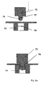
- FIG. 5a Another and particularly practical way to produce form-locking connections is in FIG. 5a to see.
- the positive mold comprises a socket 73 and a pin 75.
- the pin 75 has in this example a cylindrical cross-section and is rounded at the top in the shape of a hemisphere. But there are also other forms for the pen conceivable.
- the positive mold is moved toward the female mold 71.
- the pin 75 is in the opening of the female mold 71.
- the two plastic films have been cold formed by the action of the pin 75 in each case to a protuberance whose shape corresponds to that of the pin 75.
- the diameter 77 of the pin 75 (with a cylindrical cross-section) is not much smaller than the diameter 78 of the circular opening of the female mold 71 (see the upper part of FIG. 5b ). Then that is the result of the cold deformation of the plastic films at the same time a positive connection between them. Because the small distance between the pin 75 and the walls of the opening of the negative mold ensures with appropriate exercise of force with the pin 75 that the generated protuberances deform accordingly. After the strong pressure of the pin in the opening, the films can be solved only with great effort again from each other (positive connection).
- a very stable form-locking connection has been created when there is a gap between the pin 75 and the wall of the female mold 71 in the pressed-in state, which corresponds to the thickness of one to two plastic films. It is understood that pin 75 and the corresponding aperture need not have a circular border; they can also have elliptical or polygonal cross-sectional areas etc. Important is only the size ratio of pin and opening to each other.
- This method of producing positive-fit connections is a one-step process in which cold forming of the plastic films and form-fitting connection are produced together without the need for further tools to deform the cup-shaped connections as described in the previous examples.
- this method is particularly efficient and inexpensive.
- the corrugated foils can be manufactured in the factory without fasteners and brought to the construction site in this state. Only at the construction site, the connecting elements (protuberances) are then generated on the slides and simultaneously connected via a positive connection. This allows a particularly high degree of flexibility, since it is only decided at the construction site of the filling body at which points the foils are connected to one another, so that special conditions of the special filling body can be taken into account.
- Fig. 5 an alternative and particularly advantageous embodiment of the cap-hole connection according to the invention is shown.
- the hole 30 is modified in such a way that the edges of the hole additionally have a curvature 32 (see part a of Fig. 5 ).
- the edges of the hole additionally have a curvature 32 (see part a of Fig. 5 ).
- the resulting positive connection for cap and hole is shown in this embodiment of the invention.
- Fig. 7 is a sheath in the open state to see.
- a foil is placed in one half 80 of the sheath.
- the insides of the two sheath halves 80 have a pre-embossed structure which is adapted to the size and orientation of the wave shape of the plastic films used (see Fig. 1 for the waveform of the plastic films and the two arrows in Fig. 7 for the orientation of the pre-embossed structure in the sheath).
- Fig. 1 for the waveform of the plastic films
- Fig. 7 for the orientation of the pre-embossed structure in the sheath.
- the right half of the sheath has connecting pins 85 at its four corners and holes (not shown) corresponding to the left half of the sheath.
- the two sheath halves 80 are slidably aligned with each other. Since the two plastic films inserted into the sheath are fixedly aligned with respect to the sheath half 80 by the inner walls of the sheath half 80 and by a pre-embossed structure, the two plastic foils are also aligned with respect to one another and prevented from slipping.
- Fig. 7 there is a plurality of holes 81 on the half halves 80, wherein a hole of a half of a half of a hole of the other half of the casing opposite, when the sheath is closed.
- the orientation of the films is particularly important, since in this case the prefabricated connecting elements are missing, which ensure a (low) adhesion between the films to be joined.
- the two films are in the closed case, in places the Holes 81 connections are generated in the manner described above.
- a negative mold is formed on one outer side of the sheath (see element 71 in FIG Fig. 5a ) and a pin on the other outside of the sheath (see item 75 in Fig. 5a ), whereupon the pin is moved into the negative mold and the connection between the foils is effected at this point.
- the liner is well suited for aligning the films.
- care must be taken that the pattern of holes 81 on the sheath, i. the spacing and size of the holes 81 coincide with the spacings and sizes of the prefabricated fasteners on the foils, so that the fasteners are accessible through the holes 81 of the sheath and can be deformed into a form fit connection.
- the sheath prevents the slides from slipping during the joining process.
- the films to be joined can be held or clamped on two opposite sides.
- a pair of plastic film consisting of two bonded plastic sheets may be joined to another pair of plastic sheets by clamping the two pairs of plastic sheets respectively at their side edges into a clamping device so as to engage in the bonding operation can not slip.
- the tools which produce the interlocking connections between the films additionally comprise means which align and hold the films which are joined together.
- two plastic films are connected to form a plastic film pair.
- This form-fit connections can be generated over the entire surface of the plastic films involved.
- two plastic film pairs can then be connected to one another only by form-fit at the edges, since the projections and / or holes in the interior of the two films are no longer accessible to the mechanical tool which performs the form-locking connection.
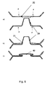
- Fig. 6 the schematic structure of a filling body 1 of four individual plastic films 10 is shown according to an embodiment of the invention, wherein a cross-sectional view is represented by the filling body 1.
- similar films 10 are bonded together, with each film 20 having approximately the same number of caps and holes.
- the two upper plastic films and the two lower plastic films with cap-hole connections are connected according to the invention (see the arrow pairs F on the right side of Fig. 6a ).
- the two resulting plastic film pairs are joined together (see the pair of arrows F of the left side of FIG Fig. 6a ).
- FIG. 6 the schematic structure of a filling body 1 of four individual plastic films is shown according to another embodiment of the invention, wherein again a cross-sectional view through the filling body is shown.
- two different types of plastic films 10, 10 ' are used.
- a plastic film 10 of the first type (see the uppermost film and the third film from above) has only projections (caps) as connecting elements
- a plastic film 10 'second type (see the second film from above and the bottom film) has only holes as connecting elements.
- a respective first type of film 10 with a second type of film 10 ' is produced. connected, since the two types of film are used alternately to the structure of the packing.
- the interlocking connections to cap-hole pairs as with reference to the Fig. 4 and 5 described.
- the density of attached fasteners is twice as high as inside the foils.
- the corrugated foil 10 has on its left edge on a hill a projection and in the subsequent valley again a projection, while inside the film 10 projections are only in valleys (see slide 10 in Fig. 6b ).
- This arrangement according to the invention of the connecting elements on the foils ensures that substantially no unconnected connecting elements remain after the filling body has been constructed from the plastic foils.
Landscapes
- Engineering & Computer Science (AREA)
- Mechanical Engineering (AREA)
- Chemical & Material Sciences (AREA)
- Thermal Sciences (AREA)
- Physics & Mathematics (AREA)
- Organic Chemistry (AREA)
- General Engineering & Computer Science (AREA)
- Chemical Kinetics & Catalysis (AREA)
- Lining Or Joining Of Plastics Or The Like (AREA)
- Buffer Packaging (AREA)
- Packages (AREA)
- Mechanical Treatment Of Semiconductor (AREA)
- Optical Head (AREA)
- Investigating Or Analyzing Materials By The Use Of Ultrasonic Waves (AREA)
Description
- Die vorliegende Erfindung bezieht sich auf die Verbindung von gewellten Kunststofffolien zu Füllkörpern, die unter anderem zur Abkühlung von Wasser in Kühltürmen Verwendung finden.
- Füllkörper werden in vielfältigen Anwendungen eingesetzt, bei denen eine Flüssigkeit und ein Gas miteinander in Kontakt gebracht werden sollen. Dabei ist es wichtig, dass der Füllkörper eine möglichst große Austauschfläche zwischen Gas und Flüssigkeit bereitstellt. Eine solche Austauschfläche kann beispielsweise für den Wärmeübergang in Nasskühltürmen genutzt werden.
-
GB-945110A US 3 798 299 zeigen den nächskommenten Stand der Technik. - Füllkörper werden oft aus vielen Einzellagen von gewellten Kunststofffolien aufgebaut. Durch die Wellung der Kunststofffolien entstehen zwischen zwei nebeneinander liegenden Kunststofffolien Kanäle, durch die die Flüssigkeit und das Gas geleitet werden können. Abhängig von der Ausrichtung der Einzellagen zueinander können die Stromrichtungen von Flüssigkeit und Gas gleichsinnig, gegensinnig oder unter einem Winkel zueinander gerichtet sein. Ein wichtiger Leistungsparameter ist in solchen Anwendungen der Druckverlust, den das Gas beim Durchströmen des Füllkörpers erfährt.
- Es gibt mittlerweile viele unterschiedliche Formen von gewellten Folien, die zum Aufbau eines Füllkörpers eingesetzt werden können. Die Formänderungen betreffen unter anderem Fragestellungen einer hohen spezifischen Oberfläche, eines niedrigen Druckverlustes, einer hohen Turbulenz der flüssigen Phase und eine niedrige Verschmutzungsrate des Füllkörpers.
- Der Fügeprozess der Einzelfolien zu einem Füllkörper kann auf sehr unterschiedliche Weisen durchgeführt werden. Ein im Stand der Technik übliches Verfahren ist das Kleben. Dieses Verfahren hat den bedeutenden Nachteil, dass ein weiterer Werkstoff in den Verbund gebracht wird, was zu möglicherweise negativen Konsequenzen für die Gesamteigenschaften des Füllkörpers führen kann, z. B. seine Brandeigenschaften oder seine chemische Resistenz. Ein Klebstoff hat außerdem in der Regel vor der Verarbeitung eine sehr begrenzte Einsatzdauer und kann oft nur in einem bestimmten Milieu (Feuchtigkeit, Temperatur) aufgebracht werden.
- Ein weiteres vorbekanntes Verfahren ist das thermische Punktschweißen. Dieses Verfahren hat den Nachteil, dass es sehr energieintensiv ist. Außerdem müssen Schweißverfahren mit einem hohen Aufwand betrieben werden, weil die Wärme nicht über den Schweißpunkt hinaus appliziert werden darf. In einem solchen Fall könnte es zu deutlichen Verformungen der Folie kommen, die die oben genannten Anwendungen des Füllkörpers nachhaltig negativ beeinflussen.
- Eine weitere Möglichkeit zum Zusammenfügen der Kunststofffolien besteht in mechanischen Verbindungstechnologien. Eine übliche mechanische Verbindung ist die so genannte Schnappverbindung, für die Hinterschnitte in die Folie eingebracht werden müssen. Derart hinterschnittene Folien haben aber den gravierenden Nachteil, dass sie sich nicht gut stapeln lassen. Da aber die Folien vor der Verbindung platzsparend gelagert bzw. transportiert werden müssen, haben hinterschnittene Folien sich im Stand der Technik nicht durchsetzen können.
- Das
US-Patent 6,544,628 schlägt ein weiteres Konzept zum Verbinden von zwei Kunststofffolien vor. Hier werden die Folien durch eine Anzahl von Formschluss-Verbindungen verbunden. Bei der Formschluss-Verbindung gemäß diesem US-Patent sind zwei becherförmige Verformungen miteinander verbunden, ein positiver Vorsprung in der Oberseite der unteren gewellten Folie und eine komplementäre negative Form an der Unterseite der oberen gewellten Folie. Die so entstandene becherförmige Verbindung wird dann durch das Applizieren von Kräften so verformt, dass ein Verhaken der Form (Formschluss) entsteht. Bei dieser vorbekannten Technik werden zunächst zwei Folien durch solche Formschluss-Verbindungen verbunden. Die entstandenen Folienpaare werden dann ausschließlich an den Rändern miteinander verbunden, da viele Verbindungen im Inneren zwischen den beiden Folienpaaren für die mechanischen Verbindungswerkzeuge nicht zugänglich sind. Bei diesem Verfahren bleibt demnach eine nicht unerhebliche Anzahl von becherartigen Verformungen unverbunden. Solche nicht verformten becherartigen Verbindungen ragen in die entsprechenden Kanäle, die sich zwischen zwei Folien befinden, hinein und erhöhen durch den reduzierten Kanalquerschnitt den Druckverlust des durchströmenden Gases. Außerdem erhöht sich für die Kanäle mit einem verringerten Querschnitt die Verschmutzungsgefahr und damit das Risiko eines vollständigen Zusetzens, was wiederum die Funktion des Füllkörpers zerstört. Außerdem tragen diese unverformten becherartigen Verbindungen praktisch nichts zur Gesamtstabilität des Füllkörpers bei. - Die vorliegende Erfindung löst mithin das technische Problem, ein Verfahren zum Verbinden von Kunststofffolien bereitzustellen, das die geschilderten Schwierigkeiten beseitigt.
- Ein weiteres Ziel der vorliegenden Erfindung ist es, Formschlussverbindungen zwischen den Kunststofffolien effizienter und kostengünstiger zu erzeugen.
- Dieses Problem wird durch ein Verfahren nach Anspruch 1, einen Füllhörper nach Anspruch 4.
- Weitere bevorzugte Ausführungsformen der Erfindung werden in den abhängigen Patentansprüchen beschrieben.
- In den Zeichnungen werden besonders bevorzugte Ausführungsformen der vorliegenden Erfindung dargestellt. Es zeigt:
- Fig. 1:
- eine schematische Darstellung des Aufbaus eines Füllkörpers aus einzelnen gewellten Kunststofffolien.
- Fig. 2:
- eine schematische Darstellung zum Erzeugen von Vorsprüngen in den Kunststofffolien mittels Kaltverformung.
- Fig. 3:
- eine schematische Darstellung der Erzeugung von Formschluss- Verbindungen in einer Ausführungsform der Erfindung.
- Fig. 4:
- eine schematische Darstellung einer Ausführungsform der Kappe- Loch-Verbindung gemäß der Erfindung.
- Fig. 5:
- eine schematische Darstellung zu einer alternativen Ausführungs- form der Kappe-Loch-Verbindung gemäß der Erfindung.
- Fig. 5a:
- eine schematische Darstellung eines Ein-Schritt-Verfahrens zur Erzeugung einer Formschlussverbindung.
- Fig. 6:
- eine schematische Querschnittsdarstellung der Anordnung von Kappen und Löchern an benachbarten Kunststofffolien gemäß ei- ner Ausführungsform der Erfindung.
- Fig. 7:
- zeigt ein geöffnetes Futteral, welches zum Ausrichten von zwei zu verbindenden Folien zueinander dient.
- Im Folgenden werden gegenwärtig bevorzugte Ausführungsbeispiele der vorliegenden Erfindung beschrieben.
-
Fig. 1 zeigt schematisch den Aufbau eines erfindungsgemäßen Füllkörpers 1, welcher aus vier gewellten Kunststofffolien 10 besteht. Es versteht sich, dass ein erfindungsgemäßer Füllkörper im Allgemeinen aus wesentlich mehr (oder auch weniger) Lagen bestehen kann. Gleichfalls kann auch eine gewellte Kunststofffolie 10 wesentlich mehr Wellenzüge, d.h. aufeinanderfolgende Berge und Täler, besitzen als inFig. 1 dargestellt. - Die spezielle Form der gewellten Kunststofffolie 10 spielt für die vorliegende Erfindung keine größere Rolle. Dementsprechend sind auch andere Formen der Wellung als die in
Fig. 1 gezeigte denkbar. - Wie in
Fig. 1 zu sehen ist, werden durch jeweils zwei benachbarte Kunststofffolien 10 eine Anzahl von Kanälen 15 definiert, durch die die Flüssigkeit bzw. das Gas geleitet werden kann, für welche der Füllkörper konstruiert ist. Dabei können zwei Kunststofffolien 10 so verbunden werden, dass ihre Wellungen in der gleichen Richtung verlaufen, was zu besonders großen Kanälen dazwischen führt. Dies ist bei manchen Anwendungen erwünscht. Es können aber die Kunststofffolien 10 auch lagenweise gegeneinander verdreht sein, was zu einem unregelmäßigen Kanalmuster und damit zu besonders turbulenten Strömungen führt, was ebenfalls je nach Anwendung erwünscht sein kann. - Die Kunststofffolien 10 können grundsätzlich aus beliebigen thermoplastischen Kunststoffen bestehen. Es können ihnen darüber hinaus Additive, Füllstoffe oder Verstärkungsstoffe zugegeben sein, um ihre Eigenschaften zu verändern. Die Kunststofffolien können auch durch verschiedene Herstellungsprozesse erstellt worden sein, die beispielweise Thermoformen, Heißpressen und Extrusion einschließen. Gegenwärtig besonders bevorzugte Kunststoffe sind Polyvinylchlorid, Polyvinylidenfluorid und Polypropylen.
- In
Fig. 2 ist schematisch die erfindungsgemäße Kaltverformung gemäß einer Ausführungsform der Erfindung dargestellt. Hierbei werden in den Kunststofffolien Vorsprünge 20 erzeugt. Aus diesen Vorsprüngen 20 werden dann im weiteren Verlauf Formschluss-Verbindungen zwischen zwei Kunststofffolien erzeugt (sieheFig. 3 undFig. 4 ). Damit eine Kaltverformung durchgeführt werden kann, muss das Material der Kunststofffolie zähe Eigenschaften bei der Kaltverformung besitzen. - Bei der Kaltverformung wird gemäß
Fig. 2 auf der einen Seite des Kunststoff-Materials 60 eine Positivform 70 verwendet und auf der anderen Seite des Kunststoff-Materials 60 eine Negativform 71. Die Negativform 71 ist dabei im Innern größer als die Positivform 70. Durch das Aufbringen einer Kraft ohne zusätzliche thermische Energie werden Positivform und Negativform ineinander geschoben und damit das dazwischen liegende Kunststoff-Material 60 entsprechend der Form der Positivform 70 zu einem Vorsprung 20 verformt, wie inFig. 2 zu sehen ist. Es ist natürlich auch denkbar, dass die Negativform 71 die Form des Vorsprungs 20 bestimmt. Das dazwischen liegende Kunststoff-Material 60 kann entweder aus einer Kunststofffolie oder aus zwei Kunststofffolien bestehen, die dann gleichzeitig bearbeitet werden. - Im Teil a) von
Fig. 2 verformt die Positivform 70 das Kunststoff-Material 60 im rechten Winkel zur Oberfläche des Materials. Im Gegensatz dazu werden im Teil b) vonFig. 2 Positivform 70 und Negativform unter einem flacheren Winkel zur Oberfläche des Kunststoff-Materials 60 geführt. Der bei diesem Schema resultierende Vorsprung 20 ist unsymmetrisch geformt, was gegebenenfalls vorteilhaft für die Stabilität einer Verbindung mit einem solchen Vorsprung ist. - Für die Abfolge zwischen dem Kaltverformungsprozesses und dem Verbinden der Kunststofffolien gibt es zwei Möglichkeiten: Bei der ersten Möglichkeit wird der Kaltverformungsprozess an einzelnen Kunststofffolien durchgeführt. Danach werden zwei Kunststofffolien zu einem Kunststofffolien-Paar verbunden. Bei der zweiten Möglichkeit werden die beiden Kunststofffolien zunächst zusammengelegt und danach wird der Kaltverformungsprozess an beiden Folien zusammen durchgeführt. Hierbei muss Sorge getragen werden, dass die Folien während des Kaltverformungsprozess zueinander fixiert bleiben, so dass sie nicht verrutschen können. Dies kann durch einen Rahmen oder durch Fixierpunkte, die durch Formanpassung der Folien entstehen, erreicht werden.
- Eine Verbindung von zwei Kunststofffolien wird gemäß der vorliegenden Erfindung durch Verbindungselemente durchgeführt. Ein Beispiel für Verbindungselemente sind die in
Fig. 3 gezeigten Vorsprünge 20, 20'. Die Verbindung wird hierbei folgendermaßen bewerkstelligt: Zunächst werden Vorsprünge 20, 20' einer oberen Kunststofffolie 10 und einer unteren Kunststofffolie 10' ineinandergefügt (ähnlich dem Ineinanderstapeln von zwei Bechern). Eine solches Zusammenfügen der Vorsprünge 20, 20' ist jeweils in den beiden oberen Teilen vonFig. 3 zu sehen. Diese Zusammenfügung von zwei Vorsprüngen stellt noch keine sehr feste Verbindung dar, da hier nur Reibungskräfte zwischen den beiden Vorsprüngen wirken. Eine Verbindung wird vielmehr durch eine Verformung (Deformierung) der Vorsprünge erreicht, wie sie den in beiden unteren Teilen vonFig. 3 zu sehen ist. Diese Verbindungsart wird als Formschluss-Verbindung 40 bezeichnet, da die deformierte Zusammenfügung der beiden Vorsprünge einen hohen Widerstand gegen das Lösen der beiden Kunststofffolien bietet, zu denen die Vorsprünge jeweils gehören. Dabei gibt es verschiedene Möglichkeiten der Verformung. - Im Teil a) von
Fig. 3 wird die Verformungskraft dezentral gegen die beiden Vorsprünge 20, 20' ausgeübt, wie dem mit F bezeichneten Kraft-Pfeil zu entnehmen ist. Eine solche Verformung führt zu einer deutlich unsymmetrischen Formschluss-Verbindung 40. Dagegen wird im Teil b) vonFig. 3 die Verformungskraft von innen gegen die beiden Vorsprünge 20, 20' ausgeübt (siehe die beiden Kraft-Pfeile F), was zu einer relativ symmetrischen Formschluss-Verbindung 40 führt. Es versteht sich, dass neben diesen beiden Beispielen noch weitere Arten zur Erzeugung von Formschluss-Verbindungen möglich sind. - Eine andere Möglichkeit zur Erzeugung von Formschluss-Verbindungen ist in
Fig. 4 dargestellt, wobei mit dieser Ausführungsform der Erfindung ebenfalls zwei Kunststofffolien verbunden werden sollen. Allerdings werden hier als Verbindungselemente jeweils ein Vorsprung 20 und ein Loch 30 verwendet. - Auf der unteren Kunststofffolie befindet sich ein Vorsprung 20, auf der oberen Kunststofffolie ist ein Loch 30 ausgebildet. Beim Zusammenfügen der Folien ergibt sich, dass jeweils ein Vorsprung einem Loch gegenüberliegt (siehe Teil a von
Fig. 4 ). - Die Vorsprünge 20 sind bei dieser Verbindungsart so geformt, dass sie eine größere Grundfläche in der Nähe der Kunststofffolie haben als am oberen Ende. Im Falle einer runden Querschnitts ist ein solcher speziell geformter Vorsprung konisch. Ein solch speziell geformter Vorsprung wird im Folgenden Kappe genannt.
- Ein Loch 30 hat die gleiche Form wie die entsprechende Kappe 20 in ihrer Projektion auf die Folienoberfläche. Die Lochgröße ist aber kleiner als diese Projektion und größer als ein Querschnitt durch das obere Ende der Kappe.
- Im Teil a) von
Fig. 4 werden Kappe 20 und Loch 30 zusammengeschoben, wie an den 4 Kraftpfeilen F zu sehen ist. Der zusammengefügte Zustand von Kappe 20 und Loch 30 ist im Teil b) vonFig. 4 zu sehen. Wegen der oben erwähnten Bedingungen an die Form und die Abmessungen von Kappe und Loch resultiert aus dem Zusammenfügen von Kappe 20 und Loch 30 eine gewisse Klemmkraft, die die beiden Kunststofffolien bereits zusammenhält. Dies ist im Teil b) vonFig. 4 daran zu sehen, dass der Rand 31 des Lochs 30 leicht angehoben ist. In Teil c) vonFig. 4 ist schließlich die Formschluss-Verbindung für die Kappe-Loch-Einheit zu sehen, die sich nach der Verformung der Kappe ergibt. - Eine weitere und besonders praktische Art, Formschlussverbindungen zu erzeugen, ist in
Figur 5a zu sehen. Im oberen Teil dieser Figur sind - ähnlich wie im linken Teil vonFig. 2 - eine Positivform und eine Negativform 71 zu sehen, zwischen denen sich zwei zusammengelegte Kunststofffolien befinden. Die Positivform umfasst einen Sockel 73 und einen Stift 75. Der Stift 75 ist hat in diesem Beispiel einen zylinderförmigen Querschnitt und ist an der Spitze abgerundet in der Form einer Halbkugel. Es sind aber auch andere Formen für den Stift denkbar. Wie durch den Pfeil angedeutet, wird die Positivform in Richtung auf die Negativform 71 bewegt. Im unteren Teil vonFigur 5a befindet sich der Stift 75 in der Öffnung der Negativform 71. Die beiden Kunststofffolien sind durch die Krafteinwirkung des Stiftes 75 jeweils zu einer Ausstülpung kaltverformt worden, deren Form derjenigen des Stiftes 75 entspricht. - Wichtig ist für dieses Verfahren, dass der Durchmesser 77 des Stiftes 75 (mit zylinderförmigem Querschnitt) nicht viel kleiner als der Durchmesser 78 der kreisförmigen Öffnung der Negativform 71 ist (siehe oberer Teil von
Figur 5b ). Dann nämlich entsteht mit der Kaltverformung der Kunststofffolien gleichzeitig eine Formschlussverbindung zwischen ihnen. Denn der geringe Abstand zwischen dem Stift 75 und den Wänden der Öffnung der Negativform sorgt bei entsprechender Kraftausübung mit dem Stift 75 dafür, dass die erzeugten Ausstülpungen sich entsprechend deformieren. Nach dem kräftigen Eindrücken des Stiftes in die Öffnung lassen sich die Folien nur noch unter hohem Kraftaufwand wieder voneinander lösen lassen (Formschlussverbindung). In Versuchen hat es sich gezeigt, dass für eine stabile Formschlussverbindung zwischen dem Stift 75 und der Wand der Negativform 71 im eingedrückten Zustand ein Abstand besteht, der der Dicke von einer halben bis vier Kunststofffolien entspricht. Somit entspricht im oberen Teil derFig. 5b die Differenz zwischen dem Durchmesser 77 des Stifts 75 und dem Durchmesser 78 der Negativform-Öffnung der Dicke von 1 bis 8 Kunststofffolien. - In bevorzugten Ausführungsformen wurde eine sehr stabile Formschlussverbindung erzeugt, wenn zwischen dem Stift 75 und der Wand der Negativform 71 im eingedrückten Zustand ein Abstand besteht, der der Dicke von ein bis zwei Kunststofffolien entspricht. Es versteht sich, dass Stift 75 und die entsprechende Öffnung nicht eine kreisförmige Umrandung besitzen müssen; sie können auch elliptische oder polygonale Querschnittsflächen etc. haben. Wichtig ist nur das Größenverhältnis von Stift und Öffnung zueinander.
- Dieses Verfahren der Erzeugung von Formschlussverbindungen ist ein Ein-Schritt-Verfahren, bei dem Kaltverformung der Kunststofffolien und Formschlussverbindung zusammen erzeugt werden, ohne dass weiteres Werkzeug benötigt wird, um - wie in den vorherigen Beispielen beschrieben - die becherförmigen Verbindungen zu deformieren. Somit ist dieses Verfahren besonders effizient und kostengünstig. Insbesondere können beim Einsatz dieses Ein-Schritt-Verfahrens die gewellten Folien in der Fabrik ohne Verbindungselemente hergestellt werden und in diesem Zustand zur Baustelle gebracht werden. Erst auf der Baustelle werden dann auf den Folien die Verbindungselemente (Ausstülpungen) erzeugt und gleichzeitig über einen Formschluss verbunden. Dies ermöglicht eine besonders große Flexibilität, da erst auf der Baustelle des Füllkörpers entschieden wird, an welchen Stellen die Folien miteinander verbunden werden, so dass besondere Gegebenheiten des speziellen Füllkörpers berücksichtigt werden können.
- In
Fig. 5 wird eine alternative und besonders vorteilhafte Ausführungsform der erfindungsgemäßen Kappe-Loch-Verbindung gezeigt. Hierbei ist das Loch 30 in der Art modifiziert dass die Ränder des Lochs zusätzlich eine Wölbung 32 aufweisen (siehe Teil a vonFig. 5 ). Im zusammengefügten Zustand von Kappe und Loch, der im Teil b) vonFig. 5 zu sehen ist, bewirkt diese Wölbung des Lochrandes, dass die Basis 21 der Kappe 20 leicht verformt ist. Dies führt zu einer verbesserten Klemmkraft zwischen Kappe 20 und Loch 30. Im Teil c) vonFig. 5 wird schließlich die resultierende Formschluss-Verbindung für Kappe und Loch bei dieser Ausführungsform der Erfindung dargestellt. - Wichtig beim Verbinden von zwei Kunststofffolien ist es, dass die Folien richtig zueinander ausgerichtet sind und beim Verbindungsvorgang nicht gegeneinander verrutschen. In
Fig. 7 ist ein Futteral im geöffneten Zustand zu sehen. Zum Aurichten wird jeweils eine Folie in eine Hälfte 80 des Futterals gelegt. Dazu haben die Innenseiten der beiden Futteral-Hälften 80 eine vorgeprägte Struktur, die an die Größe und Orientierung der Wellenform der verwendeten Kunststofffolien angepasst ist (sieheFig. 1 für die Wellenform der Kunststofffolien und die beiden Pfeile inFig. 7 für die Orientierung der vorgeprägten Stuktur im Futteral). Wie inFig. 7 zu sehen ist, hat die rechte Futteral-Hälfte an ihren vier Ecken Verbindungsstifte 85 und die linke Futteralhälfte entsprechende Löcher (nicht gezeigt). Wenn die Verbindungsstifte 85 in den Löchern platziert werden, sind die beiden Futteral-Hälften 80 rutschfest gegeneinander ausgerichtet. Da die beiden in das Futteral eingelegten Kunststofffolien durch die Innenwände der Futteral-Hälfte 80 sowie durch vorgeprägte Struktur fest gegenüber der Futteral-Hälfte 80 ausgerichtet sind, sind auch die beiden Kunststofffolien zueinander ausgerichtet und gegenüber einem Verrutschen gesichert. Wie gleichfallsFig. 7 zu entnehmen ist, befindet sich eine Vielzahl von Löchern 81 auf den Futteralhälften 80, wobei ein Loch der einen Futteral-Hälfte einem Loch der anderen Futteral-Hälfte gegenüberliegt, wenn das Futteral geschlossen ist. - Beim oben beschriebenen Ein-Schritt-Verfahren zur Erzeugung von Verbindungen ist die Ausrichtung der Folien besonders wichtig, da hierbei die vorgefertigten Verbindungselemente fehlen, welche eine (geringe) Haftung zwischen den zu verbindenden Folien gewährleisten. Wenn beim Ein-Schritt-Verfahren sich die beiden Folien in dem geschlossenen Futteral befinden, können an den Stellen der Löcher 81 Verbindungen in der oben beschriebenen Weise erzeugt werden. Dazu wird an der einen Außenseite des Futterals eine Negativform (siehe Element 71 in
Fig. 5a ) platziert und an der anderen Außenseite des Futterals ein Stift (siehe Element 75 inFig. 5a ), woraufhin der Stift in die Negativform hineinbewegt wird und die Verbindung zwischen den Folien an dieser Stelle bewirkt wird. - Aber auch für die Verfahren zur Verbindung von zwei Folien, bei denen die Folien schon zueinander passende, vorgefertigte Verbindungselemente aufweisen (z.B. Vorspruch/Loch oder zwei becherförmige Vorsprünge), ist das Futteral zur Ausrichtung der Folien gut geeignet. Bei diesen Verfahren ist aber darauf zu achten, dass das Muster der Löcher 81 auf dem Futteral, d.h. die Abstände und Größe der Löcher 81, mit den Abständen und Größen der vorgefertigten Verbindungselemente auf den Folien übereinstimmt, damit die Verbindungselemente durch die Löcher 81 des Futterals zugänglich sind und zu einer Formschlussverbindung verformt werden können. Auch bei diesen Verfahren zur Verbindung von zwei Folien verhindert das Futteral ein Verrutschen der Folien beim Verbindungsvorgang.
- Außer dem beschriebenen Futteral gibt es auch andere Vorrichtungen, die die zu verbindenden Folien gegeneinander auszurichten und ein Verrutschen verhindern können. Beispielsweise können die zu verbindenden Folien an jeweils zwei gegenüberliegenden Seiten festgehalten oder eingespannt werden. Insbesondere kann beim Aufbau eines Füllkörpers ein Kunststofffolien-Paar, das aus zwei verbundenen Kunststofffolien besteht, mit einem anderen Kunststofffolien-Paar verbunden werden, indem die beiden Kunststofffolien-Paare jeweils an ihren Seitenrändern in eine Festklemm-Vorrichtung eingespannt werden, so dass sie beim Verbindungsvorgang nicht verrutschen können. Weiterhin ist es auch denkbar, dass die Werkzeuge, die die Formschlussverbindungen zwischen den Folien erzeugen, zusätzlich Einrichtungen aufweisen, welche die Folien, die miteinander verbunden werden, ausrichten und festhalten.
- In
Fig. 6 sind zwei Beispiele für Verbindungsschemata gemäß einer Ausführungsform vorliegenden Erfindung zu sehen. - Beim Aufbau des Füllkörpers werden zwei Kunststofffolien zu einem Kunststofffolien-Paar verbunden. Hierbei können Formschluss-Verbindungen über die gesamte Fläche der beteiligten Kunststofffolien erzeugt werden. Zwei Kunststofffolien-Paare können dann allerdings nur noch an den Rändern miteinander durch Formschluss verbunden werden, da die Vorsprünge und / oder Löcher im Innern der beiden Folien nicht mehr für das mechanische Werkzeug, welches die Formschluss-Verbindung durchführt, zugänglich sind.
- Im Teil a) von
Fig. 6 wird der schematische Aufbau eines Füllkörpers 1 aus vier einzelnen Kunststofffolien 10 gemäß einer Ausführungsform der Erfindung gezeigt, wobei eine Querschnittsansicht durch den Füllkörper 1 wiedergegeben ist. In diesem Beispiel werden gleichartige Folien 10 miteinander verbunden, wobei jede Folie 20 ungefähr die gleiche Anzahl von Kappen und Löchern besitzt. Zunächst werden die beiden oberen Kunststofffolien und die beiden unteren Kunststofffolien mit Kappe-Loch-Verbindungen gemäß der Erfindung verbunden (siehe die Pfeilpaare F auf der rechten Seite vonFig. 6a ). Danach werden die beiden resultierenden Kunststofffolien-Paare miteinander verbunden (siehe das Pfeilpaar F der der linken Seite vonFig. 6a ). - In Teil b) von
Fig. 6 wird der schematische Aufbau eines Füllkörpers 1 aus vier einzelnen Kunststofffolien gemäß einer anderen Ausführungsform der Erfindung gezeigt, wobei wieder eine Querschnittsansicht durch den Füllkörper gezeigt wird. In dieser Ausführungsform werden zwei verschiedenartige Kunststofffolien 10, 10' verwendet. Eine Kunststofffolie 10 erster Art (siehe die oberste Folie und die dritte Folie von oben) hat nur Vorsprünge (Kappen) als Verbindungselemente, eine Kunststofffolie 10' zweiter Art (siehe die zweite Folie von oben und die unterste Folie) hat nur Löcher als Verbindungselemente. Bei dem gezeigten Verbindungsschema wird jeweils eine Folie erster Art 10 mit einer Folie zweiter Art 10' verbunden, da die beiden Folienarten alternierend zum Aufbau des Füllkörpers verwendet werden. Demnach werden die Formschluss-Verbindungen an Kappe-Loch-Paaren, wie sie mit Bezug auf dieFig. 4 und5 beschrieben wurden, durchgeführt. - Entscheidend ist aber noch ein weiteres Merkmal der Ausführungsform aus
Fig. 6b . An den Rändern der gezeigten vier Folien (hier in der Querschnittsansicht am linken und rechten Rand) ist die Dichte von angebrachten Verbindungselemente doppelt so hoch wie im Innern der Folien. Beispielsweise besitzt die gewellte Folie 10 an ihrem linken Rand auf einem Berg einen Vorsprung und im darauffolgenden Tal wieder einen Vorsprung, während im Inneren der Folie 10 sich Vorsprünge nur in Tälern befinden (siehe Folie 10 inFig. 6b ). Gleiches gilt für die Anordnung der Löcher auf der Folie 10'. Durch diese erfindungsgemäße Anordnung der Verbindungselemente auf den Folien ist gewährleistet, dass im Wesentlichen keine unverbundenen Verbindungselemente zurückbleiben, nachdem der Füllkörper aus den Kunststofffolien aufgebaut worden ist. Bei dem Aufbau gemäßFig. 6b werden zunächst zwei unterschiedliche Kunststofffolien 10, 10' zu einem Kunststofffolien-Paar verbunden, wobei auch bei dieser Anordnung der Verbindungselemente über die gesamte Fläche Formschluss-Verbindungen erzeugt werden können. Für das anschließende Verbinden von Kunststofffolien-Paaren bleiben nur an Rändern noch unverbundene Verbindungselemente übrig, die zur Formschluss-Verbindung der Kunststofffolien-Paare zusammengefügt werden können. Damit können im Wesentlichen alle Verbindungselemente der Kunststofffolien zu Formschluss-Verbindungen verbunden werden. Im Innern der Verbindungsfläche zwischen den beiden Kunststofffolien-Paaren bilden sich statt Formschluss-Verbindungen Stützflächen aus, die aus zwei glatten Flächen gebildet werden, die zu einem der beteiligten Kunststofffolien-Paare gehören (siehe die beiden Flächen 18 inFig. 6b ).
Claims (12)
- Verfahren zum Erzeugen einer Formschlussverbindung zwischen zwei Kunststofffolien, aufweisend die folgenden Schritte:In Kontakt Bringen der beiden Kunststofffolien an einer Kontaktstelle, wobei die Kunststofffolien an der Kontaktstelle im Wesentlichen parallel zueinander verlaufen;Positionieren einer Negativform mit einer Öffnung in der Nähe der Kontaktstelle der beiden Kunststofffolien; undBewegen eines Stiftes von der anderen Seite der sich kontaktierenden Kunststofffolien her in Richtung der Negativform und anschließendes Hineindrücken des Stiftes in die Negativform, so dass die zwischen Negativform und Stift liegenden beiden Kunststofffolien an der Kontaktstelle kaltverformt werden,wobei im eingedrückten Zustand zwischen dem Stift und der Wand der Negativform ein Abstand besteht, der der Dicke von einer halben bis vier Kunststofffolien entspricht, so dass gleichzeitig mit der Kaltverformung der beiden Kunststofffolien auch eine Formschlussverbindung zwischen den beiden Kunststofffolien entsteht.
- Verfahren nach Anspruch 1, wobei im eingedrückten Zustand zwischen dem Stift und der Wand der Negativform ein Abstand besteht, der der Dicke von ein bis drei Kunststofffolien entspricht.
- Verfahren nach Anspruch 1, wobei im eingedrückten Zustand zwischen dem Stift und der Wand der Negativform ein Abstand besteht, der der Dicke von ein bis zwei Kunststofffolien entspricht.
- Füllkörper, umfassend eine Mehrzahl von Kunststofffolien, die jeweils gewellt sind, wobei eine Kunststofffolie jeweils eine Mehrzahl von Verbindungselementen aufweist, durch die eine Kunststofffolie mit anderen Kunststofffolien durch eine Mehrzahl von Formschluss-Verbindungen verbunden werden kann, wobei der Füllkörper so aufgebaut ist, dass jeweils zwei Kunststofffolien zu einem Kunststofffolien-Paar verbunden werden und Kunststofffolien-Paare jeweils mit anderen Kunststofffolien-Paaren verbunden werden, dadurch gekennzeichnet, dass die Verbindungselemente auf den Kunststofffolien so positioniert sind, dass beim Zusammenfügen von zwei Kunststofffolien zu einem Kunststofffolien-Paar die noch unverbundenen Verbindungselemente auf den einander gegenüberliegenden Seiten der beiden Kunststofffolien zu Verbindungselemente-Paaren zusammengefügt werden können, wobei diese Verbindungselemente-Paare über die gesamte Fläche der beiden Folien verteilt sind, und
dass beim Verbinden von zwei Kunststofffolien-Paaren miteinander die noch unverbundenen Verbindungselemente auf den einander gegenüberliegenden Seiten der beiden Kunststofffolien-Paare durch eine Formschlussverbindung zu Verbindungselemente-Paaren zusammengefügt werden können, wobei diese Verbindungselemente-Paare sich ausschließlich in der Nähe der Ränder der beiden Kunststofffolien-Paare befinden,
so dass beim sukzessiven Aufbau des Füllkörpers aus den einzelnen Kunststofffolien im Wesentlichen alle Verbindungselemente, die sich auf den Kunststofffolien befinden, paarweise zu Formschluss-Verbindungen verbunden werden können. - Füllkörper nach Anspruch 4, wobei ein Verbindungselemente-Paar, das beim Aufbau des Füllkörpers verbunden wird, jeweils aus einem Vorsprung und einem Loch besteht.
- Füllkörper nach Anspruch 5, wobei die Löcher auf einer Kunststofffolie von beiden Seiten mit Vorsprüngen von benachbarten Kunststofffolien verbunden werden können.
- Füllkörper nach Anspruch 5 oder 6, wobei die Ränder der Löcher gewölbt sind.
- Füllkörper nach einem der Ansprüche 5 - 7, wobei die Vorsprünge eine größere Querschnittsfläche an dem Ende in der Nähe der Kunststofffolie haben als an ihrem anderen Ende.
- Füllkörper nach einem der Ansprüche 5 - 8, aufweisend zwei Arten von Kunststofffolien, wobei eine Kunststofffolie erster Art deutlich mehr Löcher als Vorsprünge aufweist und wobei eine Kunststofffolie zweiter Art deutlich mehr Vorsprünge als Löcher aufweist.
- Füllkörper nach einem der Ansprüche 4 - 9, wobei eine Formschluss-Verbindung zwischen paarigen Verbindungselementen durch eine Kraftaufbringung realisiert wird, die dezentral gegen ein an der Formschluss-Verbindung beteiligtes Verbindungselement drückt.
- Füllkörper nach einem der Ansprüche 4 - 9, wobei eine Formschluss-Verbindung zwischen paarigen Verbindungselementen durch eine Kraftaufbringung realisiert wird, die von innen gegen ein an der Formschluss-Verbindung beteiligtes Verbindungselement drückt.
- Füllkörper nach einem der Ansprüche 4 - 11, wobei jede der Kunststofffolien aus thermoplastischem Kunststoff besteht.
Applications Claiming Priority (2)
| Application Number | Priority Date | Filing Date | Title |
|---|---|---|---|
| DE102006061043A DE102006061043A1 (de) | 2006-12-22 | 2006-12-22 | Füllkörper |
| PCT/EP2007/010748 WO2008077474A1 (de) | 2006-12-22 | 2007-12-10 | Füllkörper |
Publications (2)
| Publication Number | Publication Date |
|---|---|
| EP2114659A1 EP2114659A1 (de) | 2009-11-11 |
| EP2114659B1 true EP2114659B1 (de) | 2011-02-16 |
Family
ID=39148800
Family Applications (1)
| Application Number | Title | Priority Date | Filing Date |
|---|---|---|---|
| EP07847045A Not-in-force EP2114659B1 (de) | 2006-12-22 | 2007-12-10 | Füllkörper |
Country Status (5)
| Country | Link |
|---|---|
| US (1) | US8844136B2 (de) |
| EP (1) | EP2114659B1 (de) |
| AT (1) | ATE498488T1 (de) |
| DE (2) | DE102006061043A1 (de) |
| WO (1) | WO2008077474A1 (de) |
Cited By (1)
| Publication number | Priority date | Publication date | Assignee | Title |
|---|---|---|---|---|
| DE102014104162A1 (de) * | 2014-03-26 | 2015-10-01 | Gea 2H Water Technologies Gmbh | Einbauelement zur Verwendung in der Kühltechnik, in der Wasseraufbereitung oder im Stoffaustausch und Verfahren zur Herstellung eines solchen Einbauelementes |
Families Citing this family (12)
| Publication number | Priority date | Publication date | Assignee | Title |
|---|---|---|---|---|
| US8771457B2 (en) * | 2008-12-19 | 2014-07-08 | Spx Cooling Technologies, Inc. | Fill pack assembly and method with bonded sheet pairs |
| US9555390B2 (en) * | 2014-05-21 | 2017-01-31 | Brentwood Industries, Inc. | Snap-lock packing element and assembly thereof for a contact assembly |
| US9931825B2 (en) * | 2014-07-09 | 2018-04-03 | The Boeing Company | Septumization of cellular cores |
| US10603846B2 (en) | 2014-08-19 | 2020-03-31 | Evapco, Inc. | Thermal fill bonding method |
| CN106794667B (zh) * | 2014-08-19 | 2020-03-20 | 艾威普科公司 | 填料热结合方法 |
| US10536758B2 (en) * | 2014-10-09 | 2020-01-14 | Thuuz, Inc. | Customized generation of highlight show with narrative component |
| CN107303481B (zh) * | 2016-04-21 | 2021-04-27 | 王宝华 | 一种塑料规整填料 |
| FR3057346B1 (fr) * | 2016-10-11 | 2019-09-13 | Hamon Thermal Europe | Corps d'echange pour tour de refroidissement |
| DE102017223691A1 (de) * | 2017-12-22 | 2019-06-27 | Reinz-Dichtungs-Gmbh | Verfahren und Vorrichtung zum Herstellen eines plattenartigen Fluidbehälters |
| EP3784480A4 (de) | 2018-04-27 | 2021-12-15 | Brentwood Industries, Inc. | Mechanische anordnung zur sicherung von folien und zugehöriges verfahren |
| WO2020068143A1 (en) * | 2018-09-25 | 2020-04-02 | Brentwood Industries, Inc. | Cross corrugated media and related method |
| US11988451B2 (en) * | 2020-04-23 | 2024-05-21 | Brentwood Industries, Inc. | Drift eliminator and method of making |
Family Cites Families (9)
| Publication number | Priority date | Publication date | Assignee | Title |
|---|---|---|---|---|
| US2288308A (en) * | 1941-04-07 | 1942-06-30 | Ivan A Williams | Punch and die |
| NL278257A (de) | 1961-05-10 | 1900-01-01 | ||
| DE2119321C3 (de) * | 1971-04-21 | 1980-05-29 | Hoechst Ag, 6000 Frankfurt | Verfahren und Vorrichtung zum Herstellen von formschlüssigen Verbindungen zwischen profilierter und ebener Folie aus thermoplastischem Kunststoff |
| US4395448A (en) * | 1981-12-22 | 1983-07-26 | Research-Cottrell, Inc. | Filling sheet attaching means for gas and liquid contact apparatus and method of assembly of plural parallel filling sheets |
| US4740334A (en) | 1987-05-29 | 1988-04-26 | Norton Company | Tower packing element with embossed surfaces |
| US5305517A (en) * | 1991-09-23 | 1994-04-26 | Schleicher Louis C | Apparatus for forming clinch joints |
| DE4208642A1 (de) * | 1992-03-18 | 1993-09-23 | Thomae Gmbh Dr K | Werkzeuge zur kaltverformung von kunststoff-folien, speziell von polypropylenfolien unterschiedlicher dicken |
| ATE254751T1 (de) * | 1999-09-15 | 2003-12-15 | Brentwood Ind Inc | Kontaktkörper und verfahren und vorrichtung zur deren herstellung |
| US6684479B2 (en) * | 2001-08-22 | 2004-02-03 | General Motors Corporation | Method and apparatus for clinching metal sheets |
-
2006
- 2006-12-22 DE DE102006061043A patent/DE102006061043A1/de not_active Withdrawn
-
2007
- 2007-12-10 WO PCT/EP2007/010748 patent/WO2008077474A1/de not_active Ceased
- 2007-12-10 EP EP07847045A patent/EP2114659B1/de not_active Not-in-force
- 2007-12-10 AT AT07847045T patent/ATE498488T1/de active
- 2007-12-10 US US12/520,636 patent/US8844136B2/en not_active Expired - Fee Related
- 2007-12-10 DE DE502007006526T patent/DE502007006526D1/de active Active
Cited By (1)
| Publication number | Priority date | Publication date | Assignee | Title |
|---|---|---|---|---|
| DE102014104162A1 (de) * | 2014-03-26 | 2015-10-01 | Gea 2H Water Technologies Gmbh | Einbauelement zur Verwendung in der Kühltechnik, in der Wasseraufbereitung oder im Stoffaustausch und Verfahren zur Herstellung eines solchen Einbauelementes |
Also Published As
| Publication number | Publication date |
|---|---|
| US20100015385A1 (en) | 2010-01-21 |
| US8844136B2 (en) | 2014-09-30 |
| EP2114659A1 (de) | 2009-11-11 |
| WO2008077474A1 (de) | 2008-07-03 |
| ATE498488T1 (de) | 2011-03-15 |
| DE102006061043A1 (de) | 2008-06-26 |
| DE502007006526D1 (de) | 2011-03-31 |
Similar Documents
| Publication | Publication Date | Title |
|---|---|---|
| EP2114659B1 (de) | Füllkörper | |
| EP1448350B1 (de) | Formwerkzeug zur herstellung von partikelschaumformteilen | |
| EP1703243B1 (de) | Wärmetauscher mit Rohren und Rippen sowie Herstellungsverfahren | |
| DE3425382C2 (de) | Verfahren zur Herstellung des Kernes eines Röhrenwärmeaustauschers | |
| WO2007076985A2 (de) | Wärmetauscher mit tiefgezogenen wärmetauscher-platten | |
| DE2353610B2 (de) | Endkappe zur Abdeckung von rohrförmigen Filterelementen | |
| DE3106313A1 (de) | Einrichtung und verfahren zum verbinden von blechen | |
| DE102015107170A1 (de) | Kühlplatte zur anordnung an einem fahrzeug-batteriemodul und herstellungsverfahren | |
| WO1998001315A1 (de) | Kraftstoffbehälter und verfahren zu seiner herstellung | |
| DE19819945C2 (de) | Einbauelement für einen Wärmetauscher, insbesondere in einem Kühlturm und Vorrichtung zur Herstellung eines solchen Einbauelements | |
| EP1389701B1 (de) | Mehrlagige Dichtung und Verfahren zum Verbinden der Lagen einer mehrlagigen Dichtung | |
| DE3316960C2 (de) | Fügestutzen für Unrundrohre in einem Tankboden für Wärmetauscher und Werkzeug zu dessen Herstellung | |
| DE102009051392A1 (de) | Verfahren zum Herstellen eines Verbundkörpers aus mindestens einem vorzufertigenden Metallbauteil und mindesten einem Kunststoffbauteil und formschlüssig gefügter Verbundkörper | |
| DE102014014083A1 (de) | Verfahren zur Herstellung eines mehrschichtigen dreidimensional geformten Bauteils und solches Bauteil | |
| WO2022058181A1 (de) | Vorrichtung zum temperieren eines bauteils und herstellungsverfahren der vorrichtung | |
| EP2651549B1 (de) | Mikrofluidisches bauteil, reaktor aus mehreren solchen bauteilen und verfahren zu deren herstellung | |
| EP1944536A2 (de) | Presshülse für eine Pressverbindung von Rohren | |
| DE4334916A1 (de) | Solarabsorber und Verfahren zu dessen Herstellung | |
| DE102017223691A1 (de) | Verfahren und Vorrichtung zum Herstellen eines plattenartigen Fluidbehälters | |
| DE102006025303B4 (de) | Einbauelement für Rieselkühler, insbesondere für Kühltürme von Kraftwerken | |
| DE10032308A1 (de) | Wellrohr sowie Wellrohranordnung | |
| DE3904250C2 (de) | Flachrohr für Wärmeaustauscher | |
| EP3464850A1 (de) | Wabenkörper für die abgasnachbehandlung | |
| DE102011108942A1 (de) | Verfahren zur Herstellung eines Bauteils aus einem ersten und einem zweiten Material und Bauteil aus einem ersten und einem zweiten Material | |
| DE19924596C2 (de) | Verfahren zur Herstellung eines Mikrostrukturapparates |
Legal Events
| Date | Code | Title | Description |
|---|---|---|---|
| PUAI | Public reference made under article 153(3) epc to a published international application that has entered the european phase |
Free format text: ORIGINAL CODE: 0009012 |
|
| 17P | Request for examination filed |
Effective date: 20090721 |
|
| AK | Designated contracting states |
Kind code of ref document: A1 Designated state(s): AT BE BG CH CY CZ DE DK EE ES FI FR GB GR HU IE IS IT LI LT LU LV MC MT NL PL PT RO SE SI SK TR |
|
| 17Q | First examination report despatched |
Effective date: 20091217 |
|
| DAX | Request for extension of the european patent (deleted) | ||
| GRAP | Despatch of communication of intention to grant a patent |
Free format text: ORIGINAL CODE: EPIDOSNIGR1 |
|
| GRAS | Grant fee paid |
Free format text: ORIGINAL CODE: EPIDOSNIGR3 |
|
| GRAA | (expected) grant |
Free format text: ORIGINAL CODE: 0009210 |
|
| AK | Designated contracting states |
Kind code of ref document: B1 Designated state(s): AT BE BG CH CY CZ DE DK EE ES FI FR GB GR HU IE IS IT LI LT LU LV MC MT NL PL PT RO SE SI SK TR |
|
| REG | Reference to a national code |
Ref country code: GB Ref legal event code: FG4D Free format text: NOT ENGLISH |
|
| REG | Reference to a national code |
Ref country code: CH Ref legal event code: EP |
|
| REG | Reference to a national code |
Ref country code: IE Ref legal event code: FG4D Free format text: LANGUAGE OF EP DOCUMENT: GERMAN |
|
| REF | Corresponds to: |
Ref document number: 502007006526 Country of ref document: DE Date of ref document: 20110331 Kind code of ref document: P |
|
| REG | Reference to a national code |
Ref country code: DE Ref legal event code: R096 Ref document number: 502007006526 Country of ref document: DE Effective date: 20110331 |
|
| REG | Reference to a national code |
Ref country code: NL Ref legal event code: VDEP Effective date: 20110216 |
|
| LTIE | Lt: invalidation of european patent or patent extension |
Effective date: 20110216 |
|
| PG25 | Lapsed in a contracting state [announced via postgrant information from national office to epo] |
Ref country code: LV Free format text: LAPSE BECAUSE OF FAILURE TO SUBMIT A TRANSLATION OF THE DESCRIPTION OR TO PAY THE FEE WITHIN THE PRESCRIBED TIME-LIMIT Effective date: 20110216 Ref country code: ES Free format text: LAPSE BECAUSE OF FAILURE TO SUBMIT A TRANSLATION OF THE DESCRIPTION OR TO PAY THE FEE WITHIN THE PRESCRIBED TIME-LIMIT Effective date: 20110527 Ref country code: GR Free format text: LAPSE BECAUSE OF FAILURE TO SUBMIT A TRANSLATION OF THE DESCRIPTION OR TO PAY THE FEE WITHIN THE PRESCRIBED TIME-LIMIT Effective date: 20110517 Ref country code: PT Free format text: LAPSE BECAUSE OF FAILURE TO SUBMIT A TRANSLATION OF THE DESCRIPTION OR TO PAY THE FEE WITHIN THE PRESCRIBED TIME-LIMIT Effective date: 20110616 Ref country code: SE Free format text: LAPSE BECAUSE OF FAILURE TO SUBMIT A TRANSLATION OF THE DESCRIPTION OR TO PAY THE FEE WITHIN THE PRESCRIBED TIME-LIMIT Effective date: 20110216 Ref country code: LT Free format text: LAPSE BECAUSE OF FAILURE TO SUBMIT A TRANSLATION OF THE DESCRIPTION OR TO PAY THE FEE WITHIN THE PRESCRIBED TIME-LIMIT Effective date: 20110216 |
|
| PG25 | Lapsed in a contracting state [announced via postgrant information from national office to epo] |
Ref country code: SI Free format text: LAPSE BECAUSE OF FAILURE TO SUBMIT A TRANSLATION OF THE DESCRIPTION OR TO PAY THE FEE WITHIN THE PRESCRIBED TIME-LIMIT Effective date: 20110216 Ref country code: BG Free format text: LAPSE BECAUSE OF FAILURE TO SUBMIT A TRANSLATION OF THE DESCRIPTION OR TO PAY THE FEE WITHIN THE PRESCRIBED TIME-LIMIT Effective date: 20110516 Ref country code: CY Free format text: LAPSE BECAUSE OF FAILURE TO SUBMIT A TRANSLATION OF THE DESCRIPTION OR TO PAY THE FEE WITHIN THE PRESCRIBED TIME-LIMIT Effective date: 20110216 Ref country code: PL Free format text: LAPSE BECAUSE OF FAILURE TO SUBMIT A TRANSLATION OF THE DESCRIPTION OR TO PAY THE FEE WITHIN THE PRESCRIBED TIME-LIMIT Effective date: 20110216 Ref country code: FI Free format text: LAPSE BECAUSE OF FAILURE TO SUBMIT A TRANSLATION OF THE DESCRIPTION OR TO PAY THE FEE WITHIN THE PRESCRIBED TIME-LIMIT Effective date: 20110216 Ref country code: NL Free format text: LAPSE BECAUSE OF FAILURE TO SUBMIT A TRANSLATION OF THE DESCRIPTION OR TO PAY THE FEE WITHIN THE PRESCRIBED TIME-LIMIT Effective date: 20110216 |
|
| REG | Reference to a national code |
Ref country code: IE Ref legal event code: FD4D |
|
| PG25 | Lapsed in a contracting state [announced via postgrant information from national office to epo] |
Ref country code: DK Free format text: LAPSE BECAUSE OF FAILURE TO SUBMIT A TRANSLATION OF THE DESCRIPTION OR TO PAY THE FEE WITHIN THE PRESCRIBED TIME-LIMIT Effective date: 20110216 Ref country code: EE Free format text: LAPSE BECAUSE OF FAILURE TO SUBMIT A TRANSLATION OF THE DESCRIPTION OR TO PAY THE FEE WITHIN THE PRESCRIBED TIME-LIMIT Effective date: 20110216 Ref country code: IE Free format text: LAPSE BECAUSE OF FAILURE TO SUBMIT A TRANSLATION OF THE DESCRIPTION OR TO PAY THE FEE WITHIN THE PRESCRIBED TIME-LIMIT Effective date: 20110216 |
|
| PG25 | Lapsed in a contracting state [announced via postgrant information from national office to epo] |
Ref country code: RO Free format text: LAPSE BECAUSE OF FAILURE TO SUBMIT A TRANSLATION OF THE DESCRIPTION OR TO PAY THE FEE WITHIN THE PRESCRIBED TIME-LIMIT Effective date: 20110216 Ref country code: SK Free format text: LAPSE BECAUSE OF FAILURE TO SUBMIT A TRANSLATION OF THE DESCRIPTION OR TO PAY THE FEE WITHIN THE PRESCRIBED TIME-LIMIT Effective date: 20110216 Ref country code: CZ Free format text: LAPSE BECAUSE OF FAILURE TO SUBMIT A TRANSLATION OF THE DESCRIPTION OR TO PAY THE FEE WITHIN THE PRESCRIBED TIME-LIMIT Effective date: 20110216 |
|
| PLBE | No opposition filed within time limit |
Free format text: ORIGINAL CODE: 0009261 |
|
| STAA | Information on the status of an ep patent application or granted ep patent |
Free format text: STATUS: NO OPPOSITION FILED WITHIN TIME LIMIT |
|
| 26N | No opposition filed |
Effective date: 20111117 |
|
| REG | Reference to a national code |
Ref country code: DE Ref legal event code: R097 Ref document number: 502007006526 Country of ref document: DE Effective date: 20111117 |
|
| PG25 | Lapsed in a contracting state [announced via postgrant information from national office to epo] |
Ref country code: IT Free format text: LAPSE BECAUSE OF FAILURE TO SUBMIT A TRANSLATION OF THE DESCRIPTION OR TO PAY THE FEE WITHIN THE PRESCRIBED TIME-LIMIT Effective date: 20110216 |
|
| BERE | Be: lapsed |
Owner name: GEA 2H WATER TECHNOLOGIES G.M.B.H. Effective date: 20111231 |
|
| PG25 | Lapsed in a contracting state [announced via postgrant information from national office to epo] |
Ref country code: MC Free format text: LAPSE BECAUSE OF NON-PAYMENT OF DUE FEES Effective date: 20111231 |
|
| REG | Reference to a national code |
Ref country code: CH Ref legal event code: PL |
|
| GBPC | Gb: european patent ceased through non-payment of renewal fee |
Effective date: 20111210 |
|
| REG | Reference to a national code |
Ref country code: FR Ref legal event code: ST Effective date: 20120831 |
|
| PG25 | Lapsed in a contracting state [announced via postgrant information from national office to epo] |
Ref country code: GB Free format text: LAPSE BECAUSE OF NON-PAYMENT OF DUE FEES Effective date: 20111210 Ref country code: LI Free format text: LAPSE BECAUSE OF NON-PAYMENT OF DUE FEES Effective date: 20111231 Ref country code: BE Free format text: LAPSE BECAUSE OF NON-PAYMENT OF DUE FEES Effective date: 20111231 Ref country code: CH Free format text: LAPSE BECAUSE OF NON-PAYMENT OF DUE FEES Effective date: 20111231 |
|
| PG25 | Lapsed in a contracting state [announced via postgrant information from national office to epo] |
Ref country code: MT Free format text: LAPSE BECAUSE OF FAILURE TO SUBMIT A TRANSLATION OF THE DESCRIPTION OR TO PAY THE FEE WITHIN THE PRESCRIBED TIME-LIMIT Effective date: 20110216 |
|
| PG25 | Lapsed in a contracting state [announced via postgrant information from national office to epo] |
Ref country code: FR Free format text: LAPSE BECAUSE OF NON-PAYMENT OF DUE FEES Effective date: 20120102 |
|
| PG25 | Lapsed in a contracting state [announced via postgrant information from national office to epo] |
Ref country code: LU Free format text: LAPSE BECAUSE OF NON-PAYMENT OF DUE FEES Effective date: 20111210 |
|
| PG25 | Lapsed in a contracting state [announced via postgrant information from national office to epo] |
Ref country code: IS Free format text: LAPSE BECAUSE OF FAILURE TO SUBMIT A TRANSLATION OF THE DESCRIPTION OR TO PAY THE FEE WITHIN THE PRESCRIBED TIME-LIMIT Effective date: 20110216 |
|
| PG25 | Lapsed in a contracting state [announced via postgrant information from national office to epo] |
Ref country code: TR Free format text: LAPSE BECAUSE OF FAILURE TO SUBMIT A TRANSLATION OF THE DESCRIPTION OR TO PAY THE FEE WITHIN THE PRESCRIBED TIME-LIMIT Effective date: 20110216 |
|
| PG25 | Lapsed in a contracting state [announced via postgrant information from national office to epo] |
Ref country code: HU Free format text: LAPSE BECAUSE OF FAILURE TO SUBMIT A TRANSLATION OF THE DESCRIPTION OR TO PAY THE FEE WITHIN THE PRESCRIBED TIME-LIMIT Effective date: 20110216 |
|
| REG | Reference to a national code |
Ref country code: AT Ref legal event code: MM01 Ref document number: 498488 Country of ref document: AT Kind code of ref document: T Effective date: 20121210 |
|
| PG25 | Lapsed in a contracting state [announced via postgrant information from national office to epo] |
Ref country code: AT Free format text: LAPSE BECAUSE OF NON-PAYMENT OF DUE FEES Effective date: 20121210 |
|
| PGFP | Annual fee paid to national office [announced via postgrant information from national office to epo] |
Ref country code: DE Payment date: 20170221 Year of fee payment: 10 |
|
| REG | Reference to a national code |
Ref country code: DE Ref legal event code: R119 Ref document number: 502007006526 Country of ref document: DE |
|
| PG25 | Lapsed in a contracting state [announced via postgrant information from national office to epo] |
Ref country code: DE Free format text: LAPSE BECAUSE OF NON-PAYMENT OF DUE FEES Effective date: 20180703 |