EP2114727B1 - Bedienanordnung für einen Abschnitt eines Kraftfahrzeuginnnenraums, Verfahren zur Herstellung einer Überkopfkonsole und Kraftfahrzeuginnenraum - Google Patents
Bedienanordnung für einen Abschnitt eines Kraftfahrzeuginnnenraums, Verfahren zur Herstellung einer Überkopfkonsole und Kraftfahrzeuginnenraum Download PDFInfo
- Publication number
- EP2114727B1 EP2114727B1 EP08727367A EP08727367A EP2114727B1 EP 2114727 B1 EP2114727 B1 EP 2114727B1 EP 08727367 A EP08727367 A EP 08727367A EP 08727367 A EP08727367 A EP 08727367A EP 2114727 B1 EP2114727 B1 EP 2114727B1
- Authority
- EP
- European Patent Office
- Prior art keywords
- film layer
- film
- functional region
- automobile interior
- functional
- Prior art date
- Legal status (The legal status is an assumption and is not a legal conclusion. Google has not performed a legal analysis and makes no representation as to the accuracy of the status listed.)
- Not-in-force
Links
- 238000004519 manufacturing process Methods 0.000 title claims abstract description 11
- 239000000463 material Substances 0.000 claims description 20
- 239000000758 substrate Substances 0.000 claims description 18
- 238000000034 method Methods 0.000 claims description 9
- 230000003993 interaction Effects 0.000 claims description 4
- 230000001681 protective effect Effects 0.000 abstract description 23
- 230000009467 reduction Effects 0.000 abstract description 4
- 230000007547 defect Effects 0.000 abstract description 2
- 230000008030 elimination Effects 0.000 abstract 2
- 238000003379 elimination reaction Methods 0.000 abstract 2
- 239000000700 radioactive tracer Substances 0.000 description 21
- 239000004033 plastic Substances 0.000 description 11
- 230000000712 assembly Effects 0.000 description 5
- 238000000429 assembly Methods 0.000 description 5
- 229920001971 elastomer Polymers 0.000 description 3
- 238000001746 injection moulding Methods 0.000 description 2
- 229920001296 polysiloxane Polymers 0.000 description 2
- VYZAMTAEIAYCRO-UHFFFAOYSA-N Chromium Chemical compound [Cr] VYZAMTAEIAYCRO-UHFFFAOYSA-N 0.000 description 1
- 238000005266 casting Methods 0.000 description 1
- 230000008859 change Effects 0.000 description 1
- 238000004140 cleaning Methods 0.000 description 1
- 238000005520 cutting process Methods 0.000 description 1
- 230000000994 depressogenic effect Effects 0.000 description 1
- 239000000806 elastomer Substances 0.000 description 1
- 238000005530 etching Methods 0.000 description 1
- 230000010354 integration Effects 0.000 description 1
- 239000010985 leather Substances 0.000 description 1
- 239000007788 liquid Substances 0.000 description 1
- 230000004048 modification Effects 0.000 description 1
- 238000012986 modification Methods 0.000 description 1
- 238000000465 moulding Methods 0.000 description 1
- 239000004417 polycarbonate Substances 0.000 description 1
- 229920000515 polycarbonate Polymers 0.000 description 1
- 230000008569 process Effects 0.000 description 1
- 239000012858 resilient material Substances 0.000 description 1
- 229920003031 santoprene Polymers 0.000 description 1
- 239000000126 substance Substances 0.000 description 1
Images


Classifications
-
- B—PERFORMING OPERATIONS; TRANSPORTING
- B60—VEHICLES IN GENERAL
- B60R—VEHICLES, VEHICLE FITTINGS, OR VEHICLE PARTS, NOT OTHERWISE PROVIDED FOR
- B60R11/00—Arrangements for holding or mounting articles, not otherwise provided for
- B60R11/02—Arrangements for holding or mounting articles, not otherwise provided for for radio sets, television sets, telephones, or the like; Arrangement of controls thereof
- B60R11/0264—Arrangements for holding or mounting articles, not otherwise provided for for radio sets, television sets, telephones, or the like; Arrangement of controls thereof for control means
-
- B—PERFORMING OPERATIONS; TRANSPORTING
- B60—VEHICLES IN GENERAL
- B60K—ARRANGEMENT OR MOUNTING OF PROPULSION UNITS OR OF TRANSMISSIONS IN VEHICLES; ARRANGEMENT OR MOUNTING OF PLURAL DIVERSE PRIME-MOVERS IN VEHICLES; AUXILIARY DRIVES FOR VEHICLES; INSTRUMENTATION OR DASHBOARDS FOR VEHICLES; ARRANGEMENTS IN CONNECTION WITH COOLING, AIR INTAKE, GAS EXHAUST OR FUEL SUPPLY OF PROPULSION UNITS IN VEHICLES
- B60K35/00—Instruments specially adapted for vehicles; Arrangement of instruments in or on vehicles
- B60K35/10—Input arrangements, i.e. from user to vehicle, associated with vehicle functions or specially adapted therefor
-
- B—PERFORMING OPERATIONS; TRANSPORTING
- B60—VEHICLES IN GENERAL
- B60R—VEHICLES, VEHICLE FITTINGS, OR VEHICLE PARTS, NOT OTHERWISE PROVIDED FOR
- B60R11/00—Arrangements for holding or mounting articles, not otherwise provided for
- B60R11/02—Arrangements for holding or mounting articles, not otherwise provided for for radio sets, television sets, telephones, or the like; Arrangement of controls thereof
-
- B—PERFORMING OPERATIONS; TRANSPORTING
- B60—VEHICLES IN GENERAL
- B60R—VEHICLES, VEHICLE FITTINGS, OR VEHICLE PARTS, NOT OTHERWISE PROVIDED FOR
- B60R13/00—Elements for body-finishing, identifying, or decorating; Arrangements or adaptations for advertising purposes
- B60R13/02—Internal Trim mouldings ; Internal Ledges; Wall liners for passenger compartments; Roof liners
-
- B—PERFORMING OPERATIONS; TRANSPORTING
- B60—VEHICLES IN GENERAL
- B60K—ARRANGEMENT OR MOUNTING OF PROPULSION UNITS OR OF TRANSMISSIONS IN VEHICLES; ARRANGEMENT OR MOUNTING OF PLURAL DIVERSE PRIME-MOVERS IN VEHICLES; AUXILIARY DRIVES FOR VEHICLES; INSTRUMENTATION OR DASHBOARDS FOR VEHICLES; ARRANGEMENTS IN CONNECTION WITH COOLING, AIR INTAKE, GAS EXHAUST OR FUEL SUPPLY OF PROPULSION UNITS IN VEHICLES
- B60K2360/00—Indexing scheme associated with groups B60K35/00 or B60K37/00 relating to details of instruments or dashboards
- B60K2360/143—Touch sensitive instrument input devices
-
- B—PERFORMING OPERATIONS; TRANSPORTING
- B60—VEHICLES IN GENERAL
- B60R—VEHICLES, VEHICLE FITTINGS, OR VEHICLE PARTS, NOT OTHERWISE PROVIDED FOR
- B60R11/00—Arrangements for holding or mounting articles, not otherwise provided for
- B60R2011/0001—Arrangements for holding or mounting articles, not otherwise provided for characterised by position
- B60R2011/0003—Arrangements for holding or mounting articles, not otherwise provided for characterised by position inside the vehicle
- B60R2011/0028—Ceiling, e.g. roof rails
-
- B—PERFORMING OPERATIONS; TRANSPORTING
- B60—VEHICLES IN GENERAL
- B60R—VEHICLES, VEHICLE FITTINGS, OR VEHICLE PARTS, NOT OTHERWISE PROVIDED FOR
- B60R13/00—Elements for body-finishing, identifying, or decorating; Arrangements or adaptations for advertising purposes
- B60R13/02—Internal Trim mouldings ; Internal Ledges; Wall liners for passenger compartments; Roof liners
- B60R2013/0287—Internal Trim mouldings ; Internal Ledges; Wall liners for passenger compartments; Roof liners integrating other functions or accessories
-
- H—ELECTRICITY
- H01—ELECTRIC ELEMENTS
- H01H—ELECTRIC SWITCHES; RELAYS; SELECTORS; EMERGENCY PROTECTIVE DEVICES
- H01H2209/00—Layers
- H01H2209/016—Protection layer, e.g. for legend, anti-scratch
-
- H—ELECTRICITY
- H01—ELECTRIC ELEMENTS
- H01H—ELECTRIC SWITCHES; RELAYS; SELECTORS; EMERGENCY PROTECTIVE DEVICES
- H01H2215/00—Tactile feedback
- H01H2215/004—Collapsible dome or bubble
- H01H2215/006—Only mechanical function
-
- H—ELECTRICITY
- H01—ELECTRIC ELEMENTS
- H01H—ELECTRIC SWITCHES; RELAYS; SELECTORS; EMERGENCY PROTECTIVE DEVICES
- H01H2217/00—Facilitation of operation; Human engineering
- H01H2217/018—Indication of switch sites
-
- H—ELECTRICITY
- H01—ELECTRIC ELEMENTS
- H01H—ELECTRIC SWITCHES; RELAYS; SELECTORS; EMERGENCY PROTECTIVE DEVICES
- H01H2217/00—Facilitation of operation; Human engineering
- H01H2217/024—Profile on actuator
-
- H—ELECTRICITY
- H01—ELECTRIC ELEMENTS
- H01H—ELECTRIC SWITCHES; RELAYS; SELECTORS; EMERGENCY PROTECTIVE DEVICES
- H01H2219/00—Legends
- H01H2219/028—Printed information
-
- H—ELECTRICITY
- H01—ELECTRIC ELEMENTS
- H01H—ELECTRIC SWITCHES; RELAYS; SELECTORS; EMERGENCY PROTECTIVE DEVICES
- H01H2221/00—Actuators
- H01H2221/002—Actuators integral with membrane
- H01H2221/004—U-shaped openings surrounding keys
-
- H—ELECTRICITY
- H01—ELECTRIC ELEMENTS
- H01H—ELECTRIC SWITCHES; RELAYS; SELECTORS; EMERGENCY PROTECTIVE DEVICES
- H01H2231/00—Applications
- H01H2231/026—Car
-
- Y—GENERAL TAGGING OF NEW TECHNOLOGICAL DEVELOPMENTS; GENERAL TAGGING OF CROSS-SECTIONAL TECHNOLOGIES SPANNING OVER SEVERAL SECTIONS OF THE IPC; TECHNICAL SUBJECTS COVERED BY FORMER USPC CROSS-REFERENCE ART COLLECTIONS [XRACs] AND DIGESTS
- Y10—TECHNICAL SUBJECTS COVERED BY FORMER USPC
- Y10T—TECHNICAL SUBJECTS COVERED BY FORMER US CLASSIFICATION
- Y10T428/00—Stock material or miscellaneous articles
- Y10T428/24—Structurally defined web or sheet [e.g., overall dimension, etc.]
- Y10T428/24273—Structurally defined web or sheet [e.g., overall dimension, etc.] including aperture
- Y10T428/24322—Composite web or sheet
- Y10T428/24331—Composite web or sheet including nonapertured component
- Y10T428/24339—Keyed
- Y10T428/24347—From both sides
Definitions
- the present invention relates generally to a film, and a plastic substrate molded behind the film, with relief areas in the plastic substrate to allow integration of various features, into the film, such as lenses, bezels, buttons usable to actuate switches for various functions in the interior of an automobile, including lamp power, Homelink® and other electrical functions, and the like.
- Automobile interiors typically comprise a variety of protective covers. These protective covers typically makeup a portion of, or the entirety of, the exposed surface that is visible to a user of the automobile. As such, the protective covers are vulnerable to dirt and debris present in the automobile interior.
- buttons are formed in these protective covers, with one or more buttons, lenses and the like fitted to and extending through the aperture such that they are accessible to a user.
- the buttons may be used to activate switches.
- the buttons may be formed by a variety of manufacturing processes, including stamping and/or injection molding.
- the apertures used for the buttons, lenses and the like may allow dirt and debris to collect beneath the protective cover of the automobile interior and/or between the protective cover and the buttons, lenses and the like.
- the existing designs require numerous parts and steps for assembly.
- Document EP 1 545 002 A2 discloses a control assembly for a portion of an automobile interior comprising a film layer, having at least one functional region, a substrate provided behind at least a portion of the film layer, at least one controllable element provided behind the film layer and engagable by an occupant of the vehicle by interacting with a corresponding one of the at least one functional regions of the film layer.
- the number of parts in an automobile interior, and the steps necessary to assemble those parts, can be reduced by providing an automobile interior with features, such as lenses, bezels and buttons, that are provided as functional regions of the protective cover of the automobile interior.
- This reduction in the parts of, and in the steps necessary to assemble the parts into, an automobile interior results in reduced capital and its associated costs as well as costs involved in assembly.
- functional features, such as lenses, bezels and buttons, as portions of the protective cover of the automobile interior a reduction of the number of apertures necessary in the protective cover can also be achieved. This reduced number of apertures in the protective cover results in a better sealed automotive interior, which is easier to clean.
- This invention relates to an automobile interior, or a portion of an automobile interior, that includes a protective outer layer according to claim 12.
- the protective outer layer includes a film layer with a plastic substrate provided behind the film layer.
- the film layer includes at least one functional region.
- an aperture in the plastic substrate is substantially aligned with each functional region.
- the functional region is a region of the film layer that allows interaction or manipulation with a mechanical, electrical or other type of control device beneath the film layer that frames, surrounds or covers a design and/or functional aspect of the protective outer layer, and/or that transmits light or the like through the protective outer layer.
- the functional region may allow interaction with a plunger of a push button switch located beneath the film layer and substantially aligned with the aperture in the plastic substrate and the functional region of the film layer.
- the functional region may allow interaction with a capacitance switch located beneath the film layer and substantially aligned with the aperture in the plastic substrate and the functional region.
- the functional region may be a bezel or a lens that surrounds, frames or covers a feature of the protective cover, such as a toggle or other switch, a dome, map, reading or other interior light or the like.
- the functional region is a part of the film layer and is formed into the film layer or provided in the film layer during manufacture of the film layer.
- additional parts or material may be inserted into a mold of the film layer to produce the functional region.
- any additional parts or materials necessary for the production of the functional region become part of the film layer.
- Fig. 1 is a representation of an overhead console assembly comprising one embodiment of an exemplary film layer according to this invention
- Fig. 2 is a sectional view of a portion of an exemplary film layer according to this invention.
- Fig. 3 is a plan view of a portion of an exemplary film design
- Fig. 4 is sectional representation of a portion of an exemplary film layer according to this invention.
- Fig. 5 is a plan view of a portion of an exemplary film layer according to this invention.
- Fig. 6 is a sectional view of a portion of a second exemplary film layer not forming part of the invention.
- Fig. 7 contains sectional views of a portion of a third and fourth exemplary film layers not forming part of the invention.
- Fig. 8 is a perspective view of a portion of an exemplary film layer not forming part of the invention.
- Fig. 9 is a sectional view of a portion of an exemplary film layer not forming part of the invention.
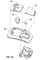
- Fig. 10 is an exploded view of a conventional overhead console
- Fig. 11 is an exploded view of an exemplary overhead console comprising an exemplary film layer not forming part of the invention
- Fig. 12 is an exploded view of an exemplary overhead console comprising an exemplary film layer not forming part of the invention
- Fig. 13 is an exploded view of an exemplary overhead console comprising an exemplary film layer not forming part of the invention
- Fig. 14 is an exploded view of a second conventional overhead console
- Fig. 15 contains perspective views of exemplary overhead console assemblies comprising an exemplary film layer according to this invention
- Fig. 16 contains perspective views of exemplary overhead console assemblies comprising an exemplary film layer according to this invention
- Fig. 17 is an exploded view of an exemplary lighting assembly comprising an exemplary film layer not forming part of the invention.
- Fig. 18 is a perspective view of an exemplary lighting assembly comprising an exemplary film layer not forming part of the invention.
- Fig. 19 is a perspective view of an exemplary portion of a roof assembly comprising an exemplary film layer not forming part of the invention.
- Fig. 20 is a perspective view of exemplary overhead console assemblies comprising exemplary film layers not forming part of the invention and various exemplary graphics that may be utilized in connection with various exemplary film layers not forming part of the invention;
- Fig. 21 contains views of portions of exemplary console assemblies comprising exemplary film layers not forming part of the invention and various exemplary graphics that may be utilized in connection with various exemplary film layers not forming part of the invention ;
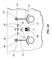
- Fig. 22 contains representations of various exemplary graphics and an exemplary graphical layout for an exemplary overhead console comprising an exemplary film layer not forming part of the invention.
- Fig. 1 illustrates one exemplary embodiment of an overhead console cover 100 usable in an overhead console assembly.
- the overhead console cover 100 includes a film 110.
- the film 110 is provided over a supporting substrate 150.
- the film 110 includes at least one exemplary embodiment of a functional region 120.
- the functional region(s) 120 can be a button, a button region or a button profile, or a series of buttons, button regions or button profiles.
- buttons, button regions or button profiles implemented by the functional regions 120 may be used to actuate any desired function of the vehicle, such as lamp power, Homelink ® , and/or other mechanical and/or electrical functions.
- the film 110 may be made of any material that has the desired characteristics, such as rigidity, moldability and/or flexibility, and through which the desired functions can be performed or actuated.
- Fig. 2 shows a sectional view of a portion of the overhead console cover 100, including the film 110 and one exemplary embodiment of a functional region 120.
- the functional region 120 includes a button region 122 of the film 110 and a rib or extension 162 of a tracer 160.
- the tracer 160 may be integrated, incorporated and/or inserted into or through the film 110.
- the tracer 160 can be formed of rubber, silicone or other synthetic and/or rubber-like materials or the like.
- the tracer 160 can be formed of Santoprene ® .
- the plastic or molded material forming the supporting substrate 150 has one or more apertures, recesses or the like 152 provided in it.
- each functional region 120, and any corresponding tracers 160, are substantially aligned with the apertures, recesses or the like 152.
- one or more switches, latches or the like 130 are provided behind or in the supporting substrate 150 and aligned with the apertures, recesses or the like 152 and the tracers 160.
- the tracers 160 may be incorporated or inserted into a mold of a film die.
- at least one tracer 160 is flexibly coupled to the film 110. It should be appreciated that, although the button region 122 is shown in Fig. 2 as usable to depress a plunger 132 of the switch 130, the switch 130 can be replaced with any suitable electrical controller, such as a capacitive switch, proximity switch or the like.
- the film 110 comprises at least one functional region 120 that is separated from other functional regions 120 and/or other areas of the film 110 by at least one slot 124, which allows additional functional properties or geometries, such as flex.
- a functional region 120 has a button region 122 that is coupled to the rest of the film 110 along or about a hinge line 170 and that is separated from the film 110 on all other sides by a slot 124.
- first and second ends of the slot 124 help create the pivot point or hinge line 170, such that the surface of the functional region 120 behaves like a cantilever, with a ridged or fixed end anchored on or about the hinge line 170 of the film 110.
- the slot 124 may be formed by any material removal or fabrication process including stamping, etching, cutting, molding or casting.
- the slot 124 may be of any suitable size and configuration. In one embodiment, the slot 124 may be substantially 3 mm wide.
- the button region 122 of the functional region 120 may also be of any suitable size and configuration. In one embodiment, the button region 122 may be approximately 25 mm wide.
- the tracer 160 may be inserted in the slot 124 such that the rib 162 extends through the slot 124.
- the tracer 160 is inserted into a mold cavity of the film 110.
- the tracer 160 that outlines a portion of the margin of the button region 122 of the functional region 120 is inserted into the mold cavity of the film 110 and the rib or protrusion 162 is formed and raised at an angle.
- the tracer 160 may be utilized to provide a tactile surface.
- the tracer 160 may be raised from the surface of the film 110.
- the tracer 160 may be substantially .8 mm above the surface of the film 110.
- the raised nature of the rib 162 of the tracer 160 in relation to the surface of the film 110 allows for tactile feedback to a user and helps define the edges of the button region 122 of the functional region 120.
- at least a portion of the tracer 160 may be set below the surface of the film 110, leaving a recess. Again, the change in elevation between the tracer 160 and the surface of the film 110 provides tactile feedback to the user and helps define the edges of the button region 122 of the functional region 120.
- the tracer 160 improves the usability of the functional region 120 and allows a user to operate the functional region 120 in low-light or no-light conditions, as well as when the user is not looking directly at the functional region 120.
- the tracer 160 may be formed using any suitable material. In various exemplary embodiments, the tracer 160 is formed using a rubber or rubber-type material. In various exemplary embodiments, the tracer 160 is formed using a soft feel material. As shown in Fig. 5 , a single slot 124 and/or a single tracer 160 extending through the slot 124 may be used to define a single functional region 120 or multiple functional regions 120.
- FIG. 6-9 Another structure that improves the tactile feedback and edge definition of the functional region(s) 120 is shown in Figs. 6-9 .
- the film 110, and at least one functional region 120 need not be substantially planar.
- at least one draw or deep recess 140 may be provided in the film 110 to help define at least one functional region 120.
- a plurality of functional regions 120 may be separated by a number of the draws or deep recesses 140 to help define, at least in part, the shapes of the functional regions 120.
- a tracer 160, a plastic cap or the like may be provided between the functional region 120 and the switches 130. In the exemplary embodiment shown in Fig. 6 , the tracer 160, the plastic cap or the like is omitted.
- the functional region 120 may include a popple 126 formed in the film 110.
- the popple 126 may be of any suitable size and shape.
- the popples 126 are square or rectangular in shape with a size of 20 to 25 mm square and may be raised .25 to .5 mm from the otherwise planar surface of the film 110.
- the film 110 may comprise a plurality of popples 126.
- the popples 126 may be spaced relatively close together.
- the popples 126 in one embodiment of the present invention may be spaced apart by 1 mm or less.
- the use of popples 126 is not limited to changing elevations and defining button regions 122.
- the film 110 need not include the raised popples 126 shown in Figs. 7-9 .
- the film 110 may include one or more popples 128 that are substantially flat, smooth and/or flush with the surface of the film 110 when in their rest state, i.e., when they are not being depressed by a user
- other structures usable to define the edges of the functional region 120 and/or to provide tactile feedback may be used.
- the film 110 may utilize capacitance switching, proximity sensors or the like.
- the film 110 including the at least one functional region 120 is formed from a single sheet of material
- the material may be any substance having suitable rigidity and flexibility characteristics
- the film 110 is a resilient material such as silicone
- the film 110 may also be formed using some other elastomer material
- at least a portion of the material forming the film 110 will be transparent or translucent, to permit emanation or backlighting
- the portion of the film 110 which is transparent or translucent may be a thinned portion of the same material forming the rest of the film 110
- the material forming the film 110 may be substantially opaque
- the film 110 including the at least one functional region 120 may also be of any suitable thickness.
- the thickness of the film 110 may range from 0,127 - 0,762 mm (005 - 030 inches).
- the film 110 may be substantially 0,254 mm (.010 inches) in thickness.
- the plastic or molded material used to form the supporting substrate 150 may also be any suitable material
- the plastic or molded material can include a polycarbonate material
- the supporting substrate 150 may also be of any suitable size, shape or configuration.
- Figs 10-18 by forming or providing one or more functional regions, such as button regions, lenses and/or bezels into the film, a reduction m cost and complexity of the assembly is achieved.
- various embodiments of the present invention offer a number of advantages, including less tooling, less capital, and fewer part numbers
- Fig 10 illustrates an exploded view of a traditional overhead console unit Automobile consoles, including overhead consoles, typically include a protective cover 200 with apertures through or into which at least one button, bezel and/or lens 202 may be fit and be accessible to the user
- the buttons may be formed by a variety of manufacturing processes, including stamping and/or injection molding
- prior art designs require numerous parts and numerous assembly steps to combine the buttons, lenses and/or bezels 202 with the protective cover 200.
- a first exemplary film 210 allows various functional regions or features 220, such as lenses, bezels and buttons, to be provided as portions of the film 210.
- Fig. 11 illustrates an exemplary film 210 having at least one functional region 220, comprising at least one bezel or bezel appearance 221, as part of the film 210.
- a second exemplary film 210 also has at least one functional region 220, comprising at least one lens or lens appearance 222, as part of the film 210.
- a third exemplary film 210 has at least one functional region 220, comprising at least one bezel or bezel appearance 221, at least one lens or lens appearance 222, and at least one button 224, as part of the film 210.
- the traditional overhead console units shown in Figs. 10 and 14 require a greater number of parts and incur associated costs to create and assemble the additional parts.
- buttons and/or button regions 224, bezels and/or bezel appearances 221 and/or lenses and/or lens appearances 222 as part of the film 210, rather than as elements separate from the film 210, also generally reduces, if not prevents, liquids, debris and other unwanted matter from entering spaces between the switches and simplifies the cleaning of consoles and other assemblies incorporating such switches.
- the use of the films 110 and/or 210 allows the use of a multitude of finishes and graphics on various consoles and automobile components.
- a die is preheated with a desired surface finish such as a metallic finish, an animal grain finish, and any other suitable finish or finishes.
- at least one desired surface finish may be printed onto and/or into the film 110 or 210. High gloss, low gloss, leather, chrome, textures, patterns, and any number of other finishes and graphics may be used in connection with the various embodiments of the film 110 or 210 according to the present invention.
- some or all of the functional regions 120 such as the buttons and/or button regions 224, bezels and/or bezel appearances 220 and/or lenses and/or lens appearances 222, have graphics thereon or therein for indicating the specific functionality, and/or providing other information associated with the functional regions 120.
- the graphics on or in the functional regions 120 such as the buttons and/or button regions 224, the bezels and/or bezel appearances 220 and/or the lenses and/or lens appearances 222 are backlit.
- Figs. 17-22 illustrate various ways an exemplary film 110 may be incorporated into a variety of interior features and consoles, including an overhead interior lighting assembly 240, and a roof assembly 250 or a portion of a roof assembly 250.
- an overhead lighting assembly 240 may incorporate a film 110 having a number of functional regions 120 usable to control and/or activate the lighting features of the overhead lighting assembly 240.
- functional regions 120 designed according to any of the above-outlined embodiments and/or according to any separate embodiments may be incorporated into a portion of the overhead lighting assembly 240 to control and/or activate at least one overhead light.
- the overhead lighting assembly 240 may take any desired shape and may comprise any number of separate parts or layers, including being a single piece.
- exemplary embodiments of a film 110 having a number of the functional regions 120 may be incorporated into a roof assembly 250 or a portion of a roof assembly 250.
- the film 110 and functional regions 120 may be designed according to any of the above-outlined embodiments and/or any separate embodiments.
- additional space may be made available in the roof assembly 250 for other features, such as vanity mirrors, control panels and/or display screens 260.
- the roof assembly 250 may have backlit designs and/or indicia that identify the functional regions 120.
- the functional regions 120 may control aspects of a display screen 260 and/or media displayed on the display screen 260.
- the functional regions 120 may be used to control any desired aspect of the automobile, including lighting controls, Homelink ® controls, media controls, power window controls and/or any other desired electrical control and/or mechanical feature of the automobile. As shown in Fig. 22 , the functional regions 120 may be defined and/or identified by backlit and/or printed graphics or indicia 121.
Landscapes
- Engineering & Computer Science (AREA)
- Mechanical Engineering (AREA)
- Chemical & Material Sciences (AREA)
- Combustion & Propulsion (AREA)
- Transportation (AREA)
- Vehicle Step Arrangements And Article Storage (AREA)
- Vehicle Interior And Exterior Ornaments, Soundproofing, And Insulation (AREA)
- Fittings On The Vehicle Exterior For Carrying Loads, And Devices For Holding Or Mounting Articles (AREA)
- Blow-Moulding Or Thermoforming Of Plastics Or The Like (AREA)
- Moulds For Moulding Plastics Or The Like (AREA)
Claims (12)
- Steuerungsanordnung (100) für einen Abschnitt eines Automobilinnenraums, welche Folgendes aufweist: eine Folienschicht (110) mit mindestens einem funktionalen Bereich (120); ein Substrat (150), das hinter mindestens einem Abschnitt der Folienschicht (110) vorgesehen ist; mindestens ein steuerbares Element (130), das hinter der Folienschicht (110) vorgesehen ist und von einem Insassen des Fahrzeugs durch Interagieren mit einem entsprechenden von dem mindestens einen funktionalen Bereich (120) der Folienschicht (110) einschaltbar ist, wobei mindestens ein Rand des funktionalen Bereiches (120) durch einen in der Folienschicht (110) vorgesehenen Schlitz (124) definiert ist, dadurch gekennzeichnet, dass die Steuerungsanordnung (100) ferner eine Rippe (162) aufweist, die in dem Schlitz (124) vorgesehen ist und über eine Außenfläche der Folienschicht (110) hinaus vorsteht.
- Steuerungsanordnung (100) nach Anspruch 1, welche ferner Folgendes aufweist: mindestens eine Öffnung (152), die in dem Substrat (150) vorgesehen ist und im Wesentlichen auf einen entsprechenden von dem mindestens einen funktionalen Bereich (120) der Folienschicht (110) ausgerichtet ist.
- Steuerungsanordnung (100) nach Anspruch 1, wobei der Abschnitt des Automobilinnenraums eine Dachkonsole (100) ist.
- Steuerungsanordnung (100) nach Anspruch 1, wobei mindestens ein Rand mindestens eines funktionalen Bereiches (120) durch eine Vertiefung in der Folienschicht (110) definiert ist.
- Steuerungsanordnung (100) nach Anspruch 1, wobei mindestens ein funktionaler Bereich (120) eine flexible Folientaste aufweist, die in der Folienschicht (110) vorgesehen ist.
- Verfahren zum Herstellen einer Dachkonsolenanordnung (100), welches Folgendes aufweist: Ausbilden mindestens eines funktionalen Bereiches (120) in einer Folienschicht (110) der Dachkonsole; Vorsehen eines Trägersubstrats (150) hinter mindestens einem Abschnitt der Folienschicht (110); Vorsehen mindestens eines steuerbaren Elements (130) hinter der Folienschicht (110), welches von einem Insassen des Fahrzeugs durch Interaktion mit einem entsprechenden von dem mindestens einen funktionalen Bereich (120) der Folienschicht (110) einschaltbar ist, wobei das Ausbilden mindestens eines funktionalen Bereiches (120) das Vorsehen eines Kanals in der Folienschicht (110) entlang mindestens eines ersten Randes mindestens eines von dem mindestens einen funktionalen Bereich (120) beinhaltet, gekennzeichnet durch Vorsehen einer Rippe (162) in dem Schlitz (124), die über eine Außenfläche der Folienschicht (110) hinaus vorsteht.
- Verfahren nach Anspruch 6, welches ferner Folgendes aufweist: Vorsehen mindestens einer Öffnung (152) in dem Trägersubstrat (150), welche im Wesentlichen auf einen entsprechenden von dem mindestens einen funktionalen Bereich (120) der Folienschicht (110) ausgerichtet ist.
- Verfahren nach Anspruch 6, welches ferner, für mindestens einen funktionalen Bereich (120), der mit einem Schlitz (124) versehen ist, das Vorsehen einer Scharnierlinie entlang mindestens eines zweiten Randes dieses funktionalen Bereiches (120) aufweist.
- Verfahren nach Anspruch 6, wobei das Vorsehen der Scharnierlinie das Dünnermachen des Materials in der Folienschicht (110) und/oder dem Trägersubstrat (150) entsprechend der Scharnierlinie beinhaltet.
- Verfahren nach Anspruch 6, wobei das Ausbilden mindestens eines funktionalen Bereiches (120) das Vorsehen mindestens einer ersten tiefen Ausnehmung in der Folienschicht (110) an mindestens einem ersten Rand des mindestens einen funktionalen Bereiches (120) beinhaltet.
- Verfahren nach Anspruch 6, wobei das Ausbilden mindestens eines funktionalen Bereiches (120) das Vorsehen mindestens einer flexiblen Folientaste in der Folienschicht (110) beinhaltet.
- Automobilinnenraum, welcher eine Steuerungsanordnung (100) nach einem der Ansprüche 1 bis 5 aufweist.
Applications Claiming Priority (2)
| Application Number | Priority Date | Filing Date | Title |
|---|---|---|---|
| US88370107P | 2007-01-05 | 2007-01-05 | |
| PCT/US2008/050287 WO2008086215A2 (en) | 2007-01-05 | 2008-01-04 | Multi-finish deep draw mold behind film |
Publications (3)
| Publication Number | Publication Date |
|---|---|
| EP2114727A2 EP2114727A2 (de) | 2009-11-11 |
| EP2114727A4 EP2114727A4 (de) | 2011-02-16 |
| EP2114727B1 true EP2114727B1 (de) | 2012-03-07 |
Family
ID=39609325
Family Applications (1)
| Application Number | Title | Priority Date | Filing Date |
|---|---|---|---|
| EP08727367A Not-in-force EP2114727B1 (de) | 2007-01-05 | 2008-01-04 | Bedienanordnung für einen Abschnitt eines Kraftfahrzeuginnnenraums, Verfahren zur Herstellung einer Überkopfkonsole und Kraftfahrzeuginnenraum |
Country Status (7)
| Country | Link |
|---|---|
| US (1) | US20100178460A1 (de) |
| EP (1) | EP2114727B1 (de) |
| JP (1) | JP2010515613A (de) |
| AT (1) | ATE548223T1 (de) |
| CA (1) | CA2672235C (de) |
| MX (1) | MX2009006563A (de) |
| WO (1) | WO2008086215A2 (de) |
Families Citing this family (10)
| Publication number | Priority date | Publication date | Assignee | Title |
|---|---|---|---|---|
| DE102007032851A1 (de) | 2007-02-07 | 2008-08-14 | Johnson Controls Automotive Electronics Gmbh | Kraftfahrzeug-Anzeigeinstrument mit umgreifendem Zeiger |
| DE102007039327B4 (de) | 2007-02-27 | 2017-08-31 | Johnson Controls Automotive Electronics Gmbh | Konisch skaliertes Anzeigeinstrument für ein Kraftfahrzeug und Verfahren zur Montage eines Zeigerinstruments |
| US8219348B2 (en) | 2009-01-22 | 2012-07-10 | Johnson Controls Technology Company | Method for calibrating and/or correcting a display device having a needle, the needle being able to move in rotation about an axis of rotation |
| US8579448B2 (en) | 2010-01-25 | 2013-11-12 | Johnson Controls Technology Company | Pointer structure of an instrument cluster |
| MX391384B (es) | 2011-08-30 | 2025-03-21 | Johnson Controls Tech Co | Sistema y método para fabricar un componente de guarnición para vehículo mediante moldeo por conformación e inyección por compresión concurrente. |
| US10464280B2 (en) | 2011-08-30 | 2019-11-05 | Shanghai Yanfeng Jinqiao Automotive Trim Systems Co. Ltd. | Trim component for vehicle interior |
| US10093268B2 (en) | 2012-08-27 | 2018-10-09 | Shanghai Yanfeng Jinqiao Automotive Trim Systems Co. Ltd. | Trim component for vehicle interior |
| CN105564247B (zh) * | 2015-12-14 | 2018-05-29 | 苏州安通林汽车内饰有限公司 | 一种车顶控制面板 |
| WO2020006290A1 (en) | 2018-06-28 | 2020-01-02 | Shanghai Yanfeng Jinqiao Automotive Trim Systems Co. Ltd. | Vehicle trim component |
| USD1081497S1 (en) * | 2025-04-16 | 2025-07-01 | Bo Lan | Car roof insulation pad |
Family Cites Families (25)
| Publication number | Priority date | Publication date | Assignee | Title |
|---|---|---|---|---|
| EP0322515A3 (de) * | 1987-12-30 | 1990-09-12 | Hewlett-Packard Company | Tastatur mit Entlüftung |
| US5205635A (en) * | 1990-07-05 | 1993-04-27 | Prince Corporation | Vehicle accessory body and integral circuit |
| DE4316998A1 (de) * | 1993-05-21 | 1994-11-24 | Eaton Controls Gmbh | Elektrischer Drucktastenschalter |
| DE19935386A1 (de) * | 1999-07-29 | 2001-02-01 | Mannesmann Vdo Ag | Anzeige mit einem durchleuchtbaren Anzeigefeld |
| DE19956542A1 (de) * | 1999-11-24 | 2001-05-31 | Mannesmann Vdo Ag | Anzeigeinstrument, insbesondere in einem Kraftfahrzeug |
| JP3527486B2 (ja) * | 2001-07-26 | 2004-05-17 | 技研株式会社 | 金属調自動車用内外装品及びその製造方法 |
| US6700086B2 (en) * | 2001-08-08 | 2004-03-02 | Yazaki Corporation | Flexible switch and method for producing the same |
| US6817610B2 (en) * | 2001-12-03 | 2004-11-16 | Siemens Aktiengesellschaft | Multiples detect apparatus and method |
| US6809280B2 (en) * | 2002-05-02 | 2004-10-26 | 3M Innovative Properties Company | Pressure activated switch and touch panel |
| US6818291B2 (en) * | 2002-08-17 | 2004-11-16 | 3M Innovative Properties Company | Durable transparent EMI shielding film |
| JP2004098485A (ja) * | 2002-09-10 | 2004-04-02 | Giken Co Ltd | 金属調自動車用内外装品及びその製造方法 |
| DE10341471A1 (de) * | 2003-02-04 | 2004-08-19 | Johnson Controls Gmbh | Innenausstattungsteil für ein Fahrzeug und Verfahren zu seiner Herstellung |
| US7221363B2 (en) * | 2003-02-12 | 2007-05-22 | Gentex Corporation | Vehicle information displays |
| US7098897B2 (en) * | 2003-06-30 | 2006-08-29 | Motorola, Inc. | Touch screen assembly and display for an electronic device |
| US20050052426A1 (en) * | 2003-09-08 | 2005-03-10 | Hagermoser E. Scott | Vehicle touch input device and methods of making same |
| DE10359297A1 (de) * | 2003-12-17 | 2005-07-28 | Lisa Dräxlmaier GmbH | Piezoschalter |
| US20050134485A1 (en) * | 2003-12-22 | 2005-06-23 | Hein David A. | Touch pad for motor vehicle and sensor therewith |
| DE102005003548A1 (de) * | 2004-02-02 | 2006-02-09 | Volkswagen Ag | Bedienelement für ein Kraftfahrzeug |
| JP4211624B2 (ja) * | 2004-02-10 | 2009-01-21 | 富士ゼロックス株式会社 | プラスチックシートの作製方法及びプラスチックシートの作製装置 |
| US7221359B2 (en) * | 2004-03-17 | 2007-05-22 | Lear Corporation | Illuminated touch switch |
| JP3906849B2 (ja) * | 2004-04-27 | 2007-04-18 | 株式会社ホンダアクセス | 車両のルーフコンソール |
| JP2005329791A (ja) * | 2004-05-19 | 2005-12-02 | Kasai Kogyo Co Ltd | 車両用コンソールボックス |
| US7091886B2 (en) * | 2004-06-09 | 2006-08-15 | Lear Corporation | Flexible touch-sense switch |
| US20060132383A1 (en) * | 2004-09-27 | 2006-06-22 | Idc, Llc | System and method for illuminating interferometric modulator display |
| DE102007032851A1 (de) * | 2007-02-07 | 2008-08-14 | Johnson Controls Automotive Electronics Gmbh | Kraftfahrzeug-Anzeigeinstrument mit umgreifendem Zeiger |
-
2008
- 2008-01-04 MX MX2009006563A patent/MX2009006563A/es not_active Application Discontinuation
- 2008-01-04 CA CA2672235A patent/CA2672235C/en not_active Expired - Fee Related
- 2008-01-04 EP EP08727367A patent/EP2114727B1/de not_active Not-in-force
- 2008-01-04 US US12/521,846 patent/US20100178460A1/en not_active Abandoned
- 2008-01-04 WO PCT/US2008/050287 patent/WO2008086215A2/en not_active Ceased
- 2008-01-04 AT AT08727367T patent/ATE548223T1/de active
- 2008-01-04 JP JP2009544995A patent/JP2010515613A/ja active Pending
Also Published As
| Publication number | Publication date |
|---|---|
| CA2672235A1 (en) | 2008-07-17 |
| EP2114727A4 (de) | 2011-02-16 |
| JP2010515613A (ja) | 2010-05-13 |
| ATE548223T1 (de) | 2012-03-15 |
| WO2008086215A2 (en) | 2008-07-17 |
| WO2008086215A3 (en) | 2008-10-09 |
| CA2672235C (en) | 2011-12-20 |
| EP2114727A2 (de) | 2009-11-11 |
| US20100178460A1 (en) | 2010-07-15 |
| MX2009006563A (es) | 2009-06-30 |
Similar Documents
| Publication | Publication Date | Title |
|---|---|---|
| EP2114727B1 (de) | Bedienanordnung für einen Abschnitt eines Kraftfahrzeuginnnenraums, Verfahren zur Herstellung einer Überkopfkonsole und Kraftfahrzeuginnenraum | |
| US6326569B1 (en) | Control panel assembly and method of making same | |
| CN106926475B (zh) | 带有无缝人车界面集成的塑料模制件 | |
| US9174536B2 (en) | Functional unit with button functions | |
| US8270158B2 (en) | Housing construction for mobile computing device | |
| US11214147B2 (en) | Vehicle interior component | |
| US20110057773A1 (en) | Keyless Entry Assembly Having Capacitance Sensor Operative for Detecting Objects | |
| US20070063980A1 (en) | Reconfigurable user interface | |
| US7902470B2 (en) | Decorative key sheet for pushbutton switches | |
| EP1952544A1 (de) | Wasserdichte abdeckung des typs imf (in-mould foil) mit zwei schichten für ein tragbares elektronisches gerät | |
| US11559965B2 (en) | Shaped part and method for producing a shaped part | |
| WO2010025160A1 (en) | Three dimensional graphics with changing appearances | |
| CN114829200B (zh) | 用于机动车的操作单元 | |
| CN100513230C (zh) | 包括刚性支承框架和柔性垫的设备部件以及具有该设备部件的机动车 | |
| US10549639B2 (en) | Control element for a motor vehicle | |
| CN1244118C (zh) | 多功能按钮开关 | |
| EP1352774B1 (de) | Bedientafel | |
| JP2014235893A (ja) | コントロールパネル | |
| US9126484B2 (en) | Method for manufacturing a human-machine interface for a motor vehicle, and human-machine interface produced by said method | |
| KR101866849B1 (ko) | 스위치 조립용 차량 도어의 소프트 어퍼 트림 및 그 양산공법 | |
| CN222793418U (zh) | 用于车辆的显示装置和车辆的内饰组件 | |
| JP2010205564A (ja) | キー及びキーシート | |
| JP2000311546A (ja) | 押釦スイッチおよびその製造法 | |
| KR20080014411A (ko) | 전면커버 구조체 |
Legal Events
| Date | Code | Title | Description |
|---|---|---|---|
| PUAI | Public reference made under article 153(3) epc to a published international application that has entered the european phase |
Free format text: ORIGINAL CODE: 0009012 |
|
| 17P | Request for examination filed |
Effective date: 20090609 |
|
| AK | Designated contracting states |
Kind code of ref document: A2 Designated state(s): AT BE BG CH CY CZ DE DK EE ES FI FR GB GR HR HU IE IS IT LI LT LU LV MC MT NL NO PL PT RO SE SI SK TR |
|
| RIN1 | Information on inventor provided before grant (corrected) |
Inventor name: KADZBAN, MARK, P. Inventor name: PIERCE, KRISTAN, M. Inventor name: HAMELINK, ROBERT Inventor name: SHOWALTER, JOHN, L. Inventor name: BUSCH, DAVID, B. |
|
| DAX | Request for extension of the european patent (deleted) | ||
| A4 | Supplementary search report drawn up and despatched |
Effective date: 20110118 |
|
| GRAP | Despatch of communication of intention to grant a patent |
Free format text: ORIGINAL CODE: EPIDOSNIGR1 |
|
| RTI1 | Title (correction) |
Free format text: CONTROL ASSEMBLY FOR A PORTION OF AN AUTOMOBILE INTERIOR, METHOD OF MAKING AN OVERHEAD CONSOLE AND AUTOMOBILE INTERIOR |
|
| GRAS | Grant fee paid |
Free format text: ORIGINAL CODE: EPIDOSNIGR3 |
|
| GRAA | (expected) grant |
Free format text: ORIGINAL CODE: 0009210 |
|
| AK | Designated contracting states |
Kind code of ref document: B1 Designated state(s): AT BE BG CH CY CZ DE DK EE ES FI FR GB GR HR HU IE IS IT LI LT LU LV MC MT NL NO PL PT RO SE SI SK TR |
|
| REG | Reference to a national code |
Ref country code: GB Ref legal event code: FG4D |
|
| REG | Reference to a national code |
Ref country code: AT Ref legal event code: REF Ref document number: 548223 Country of ref document: AT Kind code of ref document: T Effective date: 20120315 Ref country code: CH Ref legal event code: EP |
|
| REG | Reference to a national code |
Ref country code: IE Ref legal event code: FG4D |
|
| REG | Reference to a national code |
Ref country code: DE Ref legal event code: R096 Ref document number: 602008013949 Country of ref document: DE Effective date: 20120503 |
|
| REG | Reference to a national code |
Ref country code: NL Ref legal event code: VDEP Effective date: 20120307 |
|
| PG25 | Lapsed in a contracting state [announced via postgrant information from national office to epo] |
Ref country code: HR Free format text: LAPSE BECAUSE OF FAILURE TO SUBMIT A TRANSLATION OF THE DESCRIPTION OR TO PAY THE FEE WITHIN THE PRESCRIBED TIME-LIMIT Effective date: 20120307 Ref country code: LT Free format text: LAPSE BECAUSE OF FAILURE TO SUBMIT A TRANSLATION OF THE DESCRIPTION OR TO PAY THE FEE WITHIN THE PRESCRIBED TIME-LIMIT Effective date: 20120307 Ref country code: NO Free format text: LAPSE BECAUSE OF FAILURE TO SUBMIT A TRANSLATION OF THE DESCRIPTION OR TO PAY THE FEE WITHIN THE PRESCRIBED TIME-LIMIT Effective date: 20120607 Ref country code: NL Free format text: LAPSE BECAUSE OF FAILURE TO SUBMIT A TRANSLATION OF THE DESCRIPTION OR TO PAY THE FEE WITHIN THE PRESCRIBED TIME-LIMIT Effective date: 20120307 |
|
| LTIE | Lt: invalidation of european patent or patent extension |
Effective date: 20120307 |
|
| PG25 | Lapsed in a contracting state [announced via postgrant information from national office to epo] |
Ref country code: GR Free format text: LAPSE BECAUSE OF FAILURE TO SUBMIT A TRANSLATION OF THE DESCRIPTION OR TO PAY THE FEE WITHIN THE PRESCRIBED TIME-LIMIT Effective date: 20120608 Ref country code: FI Free format text: LAPSE BECAUSE OF FAILURE TO SUBMIT A TRANSLATION OF THE DESCRIPTION OR TO PAY THE FEE WITHIN THE PRESCRIBED TIME-LIMIT Effective date: 20120307 Ref country code: LV Free format text: LAPSE BECAUSE OF FAILURE TO SUBMIT A TRANSLATION OF THE DESCRIPTION OR TO PAY THE FEE WITHIN THE PRESCRIBED TIME-LIMIT Effective date: 20120307 |
|
| REG | Reference to a national code |
Ref country code: AT Ref legal event code: MK05 Ref document number: 548223 Country of ref document: AT Kind code of ref document: T Effective date: 20120307 |
|
| PG25 | Lapsed in a contracting state [announced via postgrant information from national office to epo] |
Ref country code: CY Free format text: LAPSE BECAUSE OF FAILURE TO SUBMIT A TRANSLATION OF THE DESCRIPTION OR TO PAY THE FEE WITHIN THE PRESCRIBED TIME-LIMIT Effective date: 20120307 |
|
| PG25 | Lapsed in a contracting state [announced via postgrant information from national office to epo] |
Ref country code: EE Free format text: LAPSE BECAUSE OF FAILURE TO SUBMIT A TRANSLATION OF THE DESCRIPTION OR TO PAY THE FEE WITHIN THE PRESCRIBED TIME-LIMIT Effective date: 20120307 Ref country code: PL Free format text: LAPSE BECAUSE OF FAILURE TO SUBMIT A TRANSLATION OF THE DESCRIPTION OR TO PAY THE FEE WITHIN THE PRESCRIBED TIME-LIMIT Effective date: 20120307 Ref country code: BE Free format text: LAPSE BECAUSE OF FAILURE TO SUBMIT A TRANSLATION OF THE DESCRIPTION OR TO PAY THE FEE WITHIN THE PRESCRIBED TIME-LIMIT Effective date: 20120307 Ref country code: IS Free format text: LAPSE BECAUSE OF FAILURE TO SUBMIT A TRANSLATION OF THE DESCRIPTION OR TO PAY THE FEE WITHIN THE PRESCRIBED TIME-LIMIT Effective date: 20120707 Ref country code: CZ Free format text: LAPSE BECAUSE OF FAILURE TO SUBMIT A TRANSLATION OF THE DESCRIPTION OR TO PAY THE FEE WITHIN THE PRESCRIBED TIME-LIMIT Effective date: 20120307 Ref country code: SE Free format text: LAPSE BECAUSE OF FAILURE TO SUBMIT A TRANSLATION OF THE DESCRIPTION OR TO PAY THE FEE WITHIN THE PRESCRIBED TIME-LIMIT Effective date: 20120307 Ref country code: RO Free format text: LAPSE BECAUSE OF FAILURE TO SUBMIT A TRANSLATION OF THE DESCRIPTION OR TO PAY THE FEE WITHIN THE PRESCRIBED TIME-LIMIT Effective date: 20120307 Ref country code: SI Free format text: LAPSE BECAUSE OF FAILURE TO SUBMIT A TRANSLATION OF THE DESCRIPTION OR TO PAY THE FEE WITHIN THE PRESCRIBED TIME-LIMIT Effective date: 20120307 |
|
| PG25 | Lapsed in a contracting state [announced via postgrant information from national office to epo] |
Ref country code: SK Free format text: LAPSE BECAUSE OF FAILURE TO SUBMIT A TRANSLATION OF THE DESCRIPTION OR TO PAY THE FEE WITHIN THE PRESCRIBED TIME-LIMIT Effective date: 20120307 Ref country code: PT Free format text: LAPSE BECAUSE OF FAILURE TO SUBMIT A TRANSLATION OF THE DESCRIPTION OR TO PAY THE FEE WITHIN THE PRESCRIBED TIME-LIMIT Effective date: 20120709 |
|
| PLBE | No opposition filed within time limit |
Free format text: ORIGINAL CODE: 0009261 |
|
| STAA | Information on the status of an ep patent application or granted ep patent |
Free format text: STATUS: NO OPPOSITION FILED WITHIN TIME LIMIT |
|
| PG25 | Lapsed in a contracting state [announced via postgrant information from national office to epo] |
Ref country code: AT Free format text: LAPSE BECAUSE OF FAILURE TO SUBMIT A TRANSLATION OF THE DESCRIPTION OR TO PAY THE FEE WITHIN THE PRESCRIBED TIME-LIMIT Effective date: 20120307 Ref country code: DK Free format text: LAPSE BECAUSE OF FAILURE TO SUBMIT A TRANSLATION OF THE DESCRIPTION OR TO PAY THE FEE WITHIN THE PRESCRIBED TIME-LIMIT Effective date: 20120307 |
|
| 26N | No opposition filed |
Effective date: 20121210 |
|
| PG25 | Lapsed in a contracting state [announced via postgrant information from national office to epo] |
Ref country code: IT Free format text: LAPSE BECAUSE OF FAILURE TO SUBMIT A TRANSLATION OF THE DESCRIPTION OR TO PAY THE FEE WITHIN THE PRESCRIBED TIME-LIMIT Effective date: 20120307 |
|
| REG | Reference to a national code |
Ref country code: DE Ref legal event code: R097 Ref document number: 602008013949 Country of ref document: DE Effective date: 20121210 |
|
| PG25 | Lapsed in a contracting state [announced via postgrant information from national office to epo] |
Ref country code: ES Free format text: LAPSE BECAUSE OF FAILURE TO SUBMIT A TRANSLATION OF THE DESCRIPTION OR TO PAY THE FEE WITHIN THE PRESCRIBED TIME-LIMIT Effective date: 20120618 |
|
| PG25 | Lapsed in a contracting state [announced via postgrant information from national office to epo] |
Ref country code: BG Free format text: LAPSE BECAUSE OF FAILURE TO SUBMIT A TRANSLATION OF THE DESCRIPTION OR TO PAY THE FEE WITHIN THE PRESCRIBED TIME-LIMIT Effective date: 20120607 |
|
| PG25 | Lapsed in a contracting state [announced via postgrant information from national office to epo] |
Ref country code: MC Free format text: LAPSE BECAUSE OF NON-PAYMENT OF DUE FEES Effective date: 20130131 |
|
| REG | Reference to a national code |
Ref country code: CH Ref legal event code: PL |
|
| GBPC | Gb: european patent ceased through non-payment of renewal fee |
Effective date: 20130104 |
|
| REG | Reference to a national code |
Ref country code: IE Ref legal event code: MM4A |
|
| REG | Reference to a national code |
Ref country code: FR Ref legal event code: ST Effective date: 20130930 |
|
| PG25 | Lapsed in a contracting state [announced via postgrant information from national office to epo] |
Ref country code: DE Free format text: LAPSE BECAUSE OF NON-PAYMENT OF DUE FEES Effective date: 20130801 Ref country code: CH Free format text: LAPSE BECAUSE OF NON-PAYMENT OF DUE FEES Effective date: 20130131 Ref country code: LI Free format text: LAPSE BECAUSE OF NON-PAYMENT OF DUE FEES Effective date: 20130131 |
|
| REG | Reference to a national code |
Ref country code: DE Ref legal event code: R119 Ref document number: 602008013949 Country of ref document: DE Effective date: 20130801 |
|
| PG25 | Lapsed in a contracting state [announced via postgrant information from national office to epo] |
Ref country code: FR Free format text: LAPSE BECAUSE OF NON-PAYMENT OF DUE FEES Effective date: 20130131 Ref country code: GB Free format text: LAPSE BECAUSE OF NON-PAYMENT OF DUE FEES Effective date: 20130104 |
|
| PG25 | Lapsed in a contracting state [announced via postgrant information from national office to epo] |
Ref country code: IE Free format text: LAPSE BECAUSE OF NON-PAYMENT OF DUE FEES Effective date: 20130104 |
|
| PG25 | Lapsed in a contracting state [announced via postgrant information from national office to epo] |
Ref country code: MT Free format text: LAPSE BECAUSE OF FAILURE TO SUBMIT A TRANSLATION OF THE DESCRIPTION OR TO PAY THE FEE WITHIN THE PRESCRIBED TIME-LIMIT Effective date: 20120307 |
|
| PG25 | Lapsed in a contracting state [announced via postgrant information from national office to epo] |
Ref country code: TR Free format text: LAPSE BECAUSE OF FAILURE TO SUBMIT A TRANSLATION OF THE DESCRIPTION OR TO PAY THE FEE WITHIN THE PRESCRIBED TIME-LIMIT Effective date: 20120307 |
|
| PG25 | Lapsed in a contracting state [announced via postgrant information from national office to epo] |
Ref country code: LU Free format text: LAPSE BECAUSE OF NON-PAYMENT OF DUE FEES Effective date: 20130104 Ref country code: HU Free format text: LAPSE BECAUSE OF FAILURE TO SUBMIT A TRANSLATION OF THE DESCRIPTION OR TO PAY THE FEE WITHIN THE PRESCRIBED TIME-LIMIT; INVALID AB INITIO Effective date: 20080104 |