EP2114763B1 - Aufblasbarer fender für boot - Google Patents
Aufblasbarer fender für boot Download PDFInfo
- Publication number
- EP2114763B1 EP2114763B1 EP07848719A EP07848719A EP2114763B1 EP 2114763 B1 EP2114763 B1 EP 2114763B1 EP 07848719 A EP07848719 A EP 07848719A EP 07848719 A EP07848719 A EP 07848719A EP 2114763 B1 EP2114763 B1 EP 2114763B1
- Authority
- EP
- European Patent Office
- Prior art keywords
- fender
- tube
- roller
- boat
- enclosure
- Prior art date
- Legal status (The legal status is an assumption and is not a legal conclusion. Google has not performed a legal analysis and makes no representation as to the accuracy of the status listed.)
- Not-in-force
Links
- 239000012530 fluid Substances 0.000 claims abstract description 17
- 239000012528 membrane Substances 0.000 description 7
- 239000000463 material Substances 0.000 description 5
- 239000007789 gas Substances 0.000 description 4
- 230000007246 mechanism Effects 0.000 description 4
- 238000000465 moulding Methods 0.000 description 4
- 230000006378 damage Effects 0.000 description 3
- XLYOFNOQVPJJNP-UHFFFAOYSA-N water Substances O XLYOFNOQVPJJNP-UHFFFAOYSA-N 0.000 description 3
- IJGRMHOSHXDMSA-UHFFFAOYSA-N Atomic nitrogen Chemical compound N#N IJGRMHOSHXDMSA-UHFFFAOYSA-N 0.000 description 2
- CURLTUGMZLYLDI-UHFFFAOYSA-N Carbon dioxide Chemical compound O=C=O CURLTUGMZLYLDI-UHFFFAOYSA-N 0.000 description 2
- 239000000853 adhesive Substances 0.000 description 2
- 230000001070 adhesive effect Effects 0.000 description 2
- 229920001971 elastomer Polymers 0.000 description 2
- 238000009434 installation Methods 0.000 description 2
- 239000012858 resilient material Substances 0.000 description 2
- 238000007789 sealing Methods 0.000 description 2
- 239000004677 Nylon Substances 0.000 description 1
- 241000612118 Samolus valerandi Species 0.000 description 1
- FAPWRFPIFSIZLT-UHFFFAOYSA-M Sodium chloride Chemical compound [Na+].[Cl-] FAPWRFPIFSIZLT-UHFFFAOYSA-M 0.000 description 1
- 208000027418 Wounds and injury Diseases 0.000 description 1
- 238000005299 abrasion Methods 0.000 description 1
- 229920005549 butyl rubber Polymers 0.000 description 1
- 229910002092 carbon dioxide Inorganic materials 0.000 description 1
- 239000001569 carbon dioxide Substances 0.000 description 1
- 238000010276 construction Methods 0.000 description 1
- 230000007797 corrosion Effects 0.000 description 1
- 238000005260 corrosion Methods 0.000 description 1
- 230000000694 effects Effects 0.000 description 1
- 239000000806 elastomer Substances 0.000 description 1
- 239000002360 explosive Substances 0.000 description 1
- 239000012634 fragment Substances 0.000 description 1
- 230000006870 function Effects 0.000 description 1
- 239000011796 hollow space material Substances 0.000 description 1
- 208000014674 injury Diseases 0.000 description 1
- 238000012432 intermediate storage Methods 0.000 description 1
- 238000000034 method Methods 0.000 description 1
- 229910052757 nitrogen Inorganic materials 0.000 description 1
- 229920001778 nylon Polymers 0.000 description 1
- 230000035515 penetration Effects 0.000 description 1
- 239000004033 plastic Substances 0.000 description 1
- 229920003023 plastic Polymers 0.000 description 1
- 239000002861 polymer material Substances 0.000 description 1
- 230000003014 reinforcing effect Effects 0.000 description 1
- 239000013535 sea water Substances 0.000 description 1
- 230000035939 shock Effects 0.000 description 1
- 238000003860 storage Methods 0.000 description 1
Images




Classifications
-
- B—PERFORMING OPERATIONS; TRANSPORTING
- B63—SHIPS OR OTHER WATERBORNE VESSELS; RELATED EQUIPMENT
- B63B—SHIPS OR OTHER WATERBORNE VESSELS; EQUIPMENT FOR SHIPPING
- B63B43/00—Improving safety of vessels, e.g. damage control, not otherwise provided for
- B63B43/18—Improving safety of vessels, e.g. damage control, not otherwise provided for preventing collision or grounding; reducing collision damage
-
- B—PERFORMING OPERATIONS; TRANSPORTING
- B63—SHIPS OR OTHER WATERBORNE VESSELS; RELATED EQUIPMENT
- B63B—SHIPS OR OTHER WATERBORNE VESSELS; EQUIPMENT FOR SHIPPING
- B63B59/00—Hull protection specially adapted for vessels; Cleaning devices specially adapted for vessels
- B63B59/02—Fenders integral with waterborne vessels or specially adapted therefor, e.g. fenders forming part of the hull or incorporated in the hull; Rubbing-strakes
-
- B—PERFORMING OPERATIONS; TRANSPORTING
- B63—SHIPS OR OTHER WATERBORNE VESSELS; RELATED EQUIPMENT
- B63B—SHIPS OR OTHER WATERBORNE VESSELS; EQUIPMENT FOR SHIPPING
- B63B59/00—Hull protection specially adapted for vessels; Cleaning devices specially adapted for vessels
- B63B59/02—Fenders integral with waterborne vessels or specially adapted therefor, e.g. fenders forming part of the hull or incorporated in the hull; Rubbing-strakes
- B63B2059/025—Fenders integral with waterborne vessels or specially adapted therefor, e.g. fenders forming part of the hull or incorporated in the hull; Rubbing-strakes pneumatic, e.g. inflatable
Definitions
- This invention relates to an inflatable fender for a boat, according to the characteristics of the preamble of independent claim 1.
- fenders When mooring at jetties or against other boats to protect the boat or boats from impact and abrasion damage.
- the fenders are usually formed of resilient plastics materials and may be hollow to allow for some deformation when absorbing the energy of an impact, for example.
- the fenders are commonly deployed, only when needed, by tying each one in place and placing them to hang at the side of the boat. On smaller boats in particular this operation can be difficult, particularly in choppy sea conditions, running the risk of the person falling overboard. There is therefore a need for a system which enables fenders to be automatically deployed when needed and automatically retracted when not needed.
- JP11301586 discloses an air bag device for absorbing impact shock.
- a number of the devices are located around the hull of the boat and are inflated by compressed air when bringing the boat alongside a pier, quay or another boat.
- the air bags are held within containers attached to the side of the boat, and when deflated are intended to retract into the containers, which are provided with hinged covers.
- a problem with this arrangement is that it depends on the air bags being elastic so as to return to the original small size when deflated. This would require the bags to be formed of relatively thin material to allow the desired degree of stretching during inflation, and high pressure compressed air would be required to inflate them.
- the fenders In order to achieve sufficient protection without the need for a high degree of inflation, the fenders would need to be made larger in the uninflated configuration, and this would lead to an unacceptable effect on the clean lines of the boat, or would take up space within the boat hull.
- an inflatable fender for a boat comprising an enclosure mounted on or in the boat hull and connectible to a fluid supply, an inflatable flexible member in the form of a flat tube rolled around a first roller mounted within the enclosure and the fluid supply being connectable to the tube to inflate the tube, the tube extending from the enclosure when inflated, and drive means being provided to rotate the roller to retract the tube when not required, the fluid supply being arranged to allow the fluid to withdraw from the tube as the tube is rolled on to the roller.
- the present invention is characterised in that a secondary roller is provided adjacent to the first roller to press on to the tube rolled therearound, such that, on inflation, the tube extends from between the first roller and the secondary roller and causes the tube to unroll from the roller.
- the retraction means comprises a vacuum pump connected to the interior of the enclosure and operable to withdraw gas from the inflatable member when the fender is no longer required, thereby retracting it into the enclosure.
- the fluid may be air, supplied by a compressor, for example through an intermediate storage tank so that a high pressure supply is readily available when needed.
- pressurised gases could be used, such as carbon dioxide or nitrogen, although these have the disadvantages of requiring heavy storage tanks and not be readily replenishable. Gases offer the additional advantage of providing additional buoyancy to the boat in an emergency.
- Another possibility would be water, which offers the advantages of ready availability and not requiring high pressure, although its relative inelasticity means that some air space within the inflatable members would still be required.
- Other disadvantages of using water are the weight added to the boat, the relatively slowness of inflation of the members, and the increased likelihood of corrosion of components coming into contact with the water, especially if sea-water is used.
- the inflatable fenders may be manufactured from elastomers, for example a butyl rubber, or from a woven polymer material provided with an fluid-tight liner.
- the inflatable flexible member is in the form of a flat tube rolled around a first roller, and a secondary roller is provided adjacent to the first roller, a fluid supply being connectable to the tube to inflate the tube extending from between the first roller and the secondary roller, thereby causing the tube to unroll from the roller, drive means being provided to rotate the roller to retract the tube when not required, the fluid supply being arranged to allow the fluid to withdraw from the tube as the tube is rolled on to the roller.
- a rotary connection may be provided to supply inflating fluid from a supply to the interior of the tube.
- the rotary connection may comprise a hose coiled around the axis of the first roller and connected at its inner end to the innermost end of the tube, the coil then tightening as the fender deploys and loosening as the fender is retracted.
- the rotary connection may comprise a rotating sealed joint on the axis of rotation of the first roller, communicating through the roller with the interior of the tube.
- the invention provides an inflatable fender system in which the fender can be rapidly deployed by the operation of a single control, such as a solenoid-operated valve, and can be equally easily retracted neatly into its enclosure when not required, without the need for the fender to resiliently inflate, thereby permitting its operation at a safe internal pressure.
- a single control such as a solenoid-operated valve
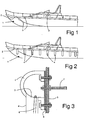
- a boat 1 is provided with an inflatable fender system consisting of a housing 2 mounted along the gunwale and having a plurality of openings 3 spaced therealong from which inflatable fenders 4 can be extended down the side of the boat's hull.
- inflatable fenders system consisting of a housing 2 mounted along the gunwale and having a plurality of openings 3 spaced therealong from which inflatable fenders 4 can be extended down the side of the boat's hull.
- FIG. 3 illustrates one embodiment of the inflatable fender system of the invention.
- the housing 2 consists of a hollow moulding which is bolted on to the hull 5 of the boat with a sealing membrane 6 interposed to ensure an airtight seal.
- a compressed air pipe 7 passes through the hull 5 to open into the housing 2.
- the pipe 7 is connected via a control valve to a compressed air tank supplied by a compressor (not shown).
- the inflatable members 4 constituting the fenders are sealed to the inner surface of the housing 2 and extend through the openings 3 when inflated by air pressure within the housing.
- Each of the members 4 contains a retraction cord 8, which is attached to the free end of the member 4 and extends back inside the housing to a common elastic cord or bungee (not shown), which can pull all the cords on the respective side of the boat simultaneously to retract the members 4 into the housing (in practice, a short length of each of the fender members 4 may be left protruding from the housing to ensure correct deployment when the housing is pressurised).
- the retraction cord 8 may itself be a discrete length of elastic cord which, when the fender is deflated, contracts to pull the inflatable member 4 back into the housing.
- Figure 4 is a longitudinal section through the housing 2, showing the retracted fender members 4 pulled into the housing by the cords 8.
- Figure 5 is a corresponding view with the fenders 4 pressurised and extended.
- FIG. 6 shows another arrangement, in which the enclosure or housing 10 is mounted on the inside wall of the hull 5, the compressed air supply pipe 7 extending through the wall of the housing 10. Apertures 11 are then provided at intervals along the hull.
- Each fender 12 consists of an elongate bottle structure having a side opening 13 which is sealed into the respective aperture 11.
- a plug 14 is attached at the upper end of the fender 12 ; this fits into the aperture 11 when the fender is retracted.
- a cord 15 extends inside the fender 12 from the lowermost point thereof through the opening to pass around a bar 16 whose function is to allow the cord to pull straight and so the plug 14 will sit straight in the aperture 11.
- the cord 15 is linked to a common elastic cord (not shown) which serves to pull all the cords in when the pressure is released.
- a cord 17, for example a length of nylon rope, is provided internally between the opposed ends of the fender to hold the plug tightly in place when the fender is retracted.
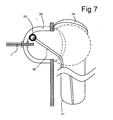
- the embodiment of Figure 7 provides a channel member 20 as the enclosure for the fenders 21 which extend through openings in the side of the hull 5 when the channel is pressurised by the compressed air supply pipe 7.
- a number of discrete openings housing individual fenders may be provided, or, as an alternative, a continuous channel may house a curtain type of fender.
- a cord 22 extends from the lowermost point inside the fender through a guide ring 23 to a common elastic cord or bungee (not shown) to pull all the cords simultaneously to retract the deflated fenders.
- Hinged covers 24 are spring-biased to close over the openings to present a clean appearance.
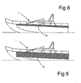
- FIGs 8 and 9 illustrate a boat 1 provided with an inflatable fender system consisting of an inflatable curtain 30 which can be extended down the side of the boat's hull, to provide a continuous fender, as shown in Figure 9 .
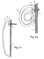
- Figures 10 and 11 illustrate one embodiment of this curtain arrangement.
- the housing and the curtain fender are combined together.
- the housing is formed of a tough resilient material 40 with a flexible membrane 41 welded to it around the edge thereof, the other side of the membrane being clamped between the mounting bracket 42 for the housing and a sealing strip 43 against the hull 5.
- At least one of the mounting bolts 44 for the housing 40 has a passageway therethrough for admission of compressed air to inflate the fender.
- the tough resilient material 40 forming the housing is moulded in a coiled form so that the material has a "memory" for this configuration, as illustrated in Figure 10 .
- the pressure caused the material 40 to unroll as the fender extends downwardly against the side of the boat, the fully extended position being illustrated in Figure 11 . Release of the pressure allows the material 40 to coil up again, to provide a neat appearance and to protect the membrane 41. If necessary, the deflation and coiling can be facilitated by connecting an extractor pump to the interior of the fender through one or more other fixing bolts.
- Figures 12 and 13 show another alternative curtain fender arrangement.
- the housing comprises two separate parts, an upper bracket 50 bolted to the side of the hull, and a lower cap moulding 51.
- the fender is formed from an inner flexible membrane 52 sealed to the outer edge of the bracket 50 and to the outer edge of the cap moulding, and an inner flexible membrane 53 held along one edge between the bracket 50 and its seal 54 against the hull, and along the other edge on the inner edge of the cap moulding 51.
- Reinforcing ribs 55 divide the membranes 52 and 53 into segments providing additional resilience in the event of impacts with the fender.
- Elastic cords or bungees 56 are provided at intervals along the fender to assist in retracting the fender when deflated.
- the segmented arrangement allows the fender system to concertina to close within the housing.
- the application of a vacuum to the fender may assist this process.
- Compressed air is introduced through a passageway 57 through at least one of the mounting bolts 58.
- Figure 12 shows the fender near to its closed position, while Figure 13 shows the extended position.
- the fender system can be incorporated into the design of new boats, but can also be arranged to be retro-fitted to existing boats.
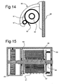
- the fender comprises a roller 60 around which is wound a flat tubular flexible member 61 having a closed end 62 so as to be inflatable when compressed air is introduced into it.
- the roller 60 is rotatable mounted within an enclosure 63 mounted on the outer surface of the boat hull 64.
- the roller 60 has at one end thereof a spring retraction mechanism 65 which is tensioned as the flexible member 61 is unreeled from the roller 60, and which can therefore retract the flexible member when the inflating pressure in it is released.
- spring retraction mechanism 65 which is tensioned as the flexible member 61 is unreeled from the roller 60, and which can therefore retract the flexible member when the inflating pressure in it is released.
- the other end of the roller 60 carries a reel 66 for a pressure hose 68 which at one end is connected to a selective source of compressed air, for example from a central supply tank in turn charged by a compressor, and at the other end is connected to the flexible member 61 at the centre of the reel through a sealed inlet.
- the hose coil 68 tightens in the manner of a watch spring as the fender extends, and loosens as the fender retracts.
- a secondary roller 67 rests against the reel 66 to ensure that significant inflation of the fender occurs only off the reel.
- the flexible member is suitably in the form of a fabric-reinforced rubber whose stiffness and internal texture ensure that there will always be a passageway for air to flow from the hose inlet to the free end on inflation, and in the other direction on deflation and retraction.
- the fender is extended by applying compressed air through the hose 68 to the flexible member rolled on to the roller 60.
- the air passes through the coiled hose, causing the free end extending beyond the secondary roller 67 to inflate, progressively unrolling the member 61 from the roller, and at the same time tensioning the spring retraction mechanism. This continues until the fender is fully extended, the pressure being maintained to hold the fender in its operative position.
- the pressure in the hose is released and the compressed air is allowed to vent to atmosphere.
- the retraction mechanism 65 rotates the roller 60 to reel in the tubular member 61, the secondary roller 67 guiding the member to lie flat on the reel, thereby ensuring that the compressed air is fully expelled.
- the configuration illustrated in Figures 14 offers the advantage of requiring no penetration of the hull, enabling easy installation on existing boats.
- Figure 16 shows an alternative arrangement to that shown in Figure 15 , in which the flexible member forming the fender is mounted on the reel 66 in such a manner that it extends into and is sealingly connected with a hollow space 66a in the reel, which in turn communicates with an inlet nozzle 66b to one side of the reel.
- a rotary connector 66c is a snap seal fit on to the nozzle 66b, and is in turn connected to a compressed air supply hose 69 which leads to a compressed air source (not shown).
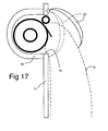
- Figures 17 and 18 show alternative configurations of the fender shown in Figure 14 .
- the fender is fitted in a housing 70 located within the boat hull 71 and communicating with the outside of the hull through an opening 72 therein.
- a spring-loaded hinged cover 73 locates over the opening to close it when the fender is not in use, the cover being displaced when the fender is inflated.
- the chain-dotted line 74 indicates the inflated state of the fender.
- the embodiment shown in Figure 18 is intended to be incorporated into the hull of a boat during construction.
- the hull 80 is formed with an overhang 81 concealing a recess in which the fender is located.
- the fender then deploys downwardly through the slot 82 defined between the overhang and the side of the hull.
Landscapes
- Chemical & Material Sciences (AREA)
- Engineering & Computer Science (AREA)
- Combustion & Propulsion (AREA)
- Mechanical Engineering (AREA)
- Ocean & Marine Engineering (AREA)
- Health & Medical Sciences (AREA)
- Public Health (AREA)
- Tents Or Canopies (AREA)
- Body Structure For Vehicles (AREA)
- Filling Or Discharging Of Gas Storage Vessels (AREA)
Claims (6)
- Aufblasbarer Fender für ein Boot, umfassend eine Einhausung (63), die an oder in dem Bootskörper montiert und mit einer Fluidzufuhr verbindbar ist, ein aufblasbares flexibles Element in der Form eines flachen Rohrs (61), das um eine innerhalb der Einhausung montierte erste Rolle (60) aufgerollt ist, wobei die Fluidzufuhr mit dem Rohr verbindbar ist, um das Rohr aufzublasen, wobei das Rohr in aufgeblasenem Zustand von der Einhausung wegsteht, und Antriebsmittel (65), die dazu vorgesehen sind, die Rolle in Drehung zu versetzen, um das Rohr zurückzuziehen, wenn dieses nicht benötigt wird, wobei die Fluidzufuhr geeignet ist, eine Fluidabfuhr aus dem Rohr zu gestatten, wenn das Rohr auf die Rolle aufgerollt wird, dadurch gekennzeichnet, dass eine zweite Rolle (67) benachbart der ersten Rolle (60) vorgesehen ist, um auf das darum gerollte Rohr derart zu drücken, dass sich beim Aufblasen das Rohr zwischen der ersten Rolle (60) und der zweiten Rolle (67) hervorerstreckt und ein Abrollen des Rohrs von der Rolle veranlasst wird.
- Aufblasbarer Fender nach Anspruch 1, dadurch gekennzeichnet, dass die Antriebsmittel einen Federantrieb (65) umfassen, der durch das Entrollen des nachgiebigen Elements beim Aufblasen desselben gespannt wird.
- Aufblasbarer Fender nach Anspruch 1 oder 2, dadurch gekennzeichnet, dass die Einhausung mit einer gelenkig angekoppelten Abdeckung versehen ist, welche durch Aufblasen und Ausdehnung des flexiblen Elements geöffnet wird.
- Aufblasbarer Fender nach Anspruch 3, dadurch gekennzeichnet, dass die gelenkig angekoppelte Abdeckung mit einer Feder versehen ist, welche die Abdeckung in Richtung der Schließstellung derselben mit Kraft beaufschlagt.
- Aufblasbarer Fender nach einem der vorgenannten Ansprüche, bei dem die Einhausung unter einem Überhang des Decks des Boots angeordnet ist, so dass dieser zwischen dem Überhang und dem Bootskörper ausbringbar ist.
- Aufblasbarer Fender nach einem der vorgenannten Ansprüche, bei dem das Fluid Druckluft ist.
Applications Claiming Priority (2)
| Application Number | Priority Date | Filing Date | Title |
|---|---|---|---|
| GB0625066A GB2444787A (en) | 2006-12-15 | 2006-12-15 | An inflatable fender for a boat |
| PCT/GB2007/050759 WO2008072019A1 (en) | 2006-12-15 | 2007-12-14 | Inflatable fender for a boat |
Publications (2)
| Publication Number | Publication Date |
|---|---|
| EP2114763A1 EP2114763A1 (de) | 2009-11-11 |
| EP2114763B1 true EP2114763B1 (de) | 2012-03-14 |
Family
ID=37712224
Family Applications (1)
| Application Number | Title | Priority Date | Filing Date |
|---|---|---|---|
| EP07848719A Not-in-force EP2114763B1 (de) | 2006-12-15 | 2007-12-14 | Aufblasbarer fender für boot |
Country Status (5)
| Country | Link |
|---|---|
| US (1) | US8136467B2 (de) |
| EP (1) | EP2114763B1 (de) |
| AT (1) | ATE549236T1 (de) |
| GB (1) | GB2444787A (de) |
| WO (1) | WO2008072019A1 (de) |
Families Citing this family (19)
| Publication number | Priority date | Publication date | Assignee | Title |
|---|---|---|---|---|
| WO2011145978A2 (ru) * | 2011-03-18 | 2011-11-24 | Goncharov Yuriy Denisovich | Парусно-моторное судно «ковчег-3» |
| ITMI20111505A1 (it) | 2011-08-05 | 2013-02-06 | Antonello Beltrami | Parabordo per imbarcazione. |
| US9365268B1 (en) | 2012-07-16 | 2016-06-14 | Bombardier Recreational Products Inc. | Fender for a watercraft |
| US10554594B2 (en) * | 2013-01-10 | 2020-02-04 | Vmware, Inc. | Method and system for automatic switching between chat windows |
| US10040523B2 (en) * | 2014-02-19 | 2018-08-07 | Jeong Yong Lee | Compressed air tank for sinking prevention |
| WO2016088033A1 (en) * | 2014-12-01 | 2016-06-09 | Dal Monte Casoni Marco Luigi | Inflatable fender apparatus |
| US9937985B2 (en) | 2015-04-16 | 2018-04-10 | Shmuel Sam Arditi | System and method for planning and predetermination of fender heights and dock location information |
| US9764808B2 (en) | 2015-04-16 | 2017-09-19 | Shmuel Sam Arditi | Enhanced system and method for controlling automatic deployment of boat fenders |
| US9440716B1 (en) | 2015-04-27 | 2016-09-13 | Shmuel Sam Arditi | Enhanced system and method for automatically deploying boat fenders |
| US10023278B1 (en) * | 2016-09-20 | 2018-07-17 | Gideon Smith | Pneumatic fender system for vessels |
| US20190138014A1 (en) * | 2017-11-06 | 2019-05-09 | G-Boats Oy | System for manoeuvring a boat |
| US11104409B2 (en) | 2017-11-06 | 2021-08-31 | G-Boats Oy | System for manoeuvring a boat |
| US11738833B1 (en) | 2020-03-31 | 2023-08-29 | Bombardier Recreational Products Inc. | Fender system for a watercraft |
| CN111731446B (zh) * | 2020-07-06 | 2021-11-26 | 华北水利水电大学 | 一种船舶防护用防撞装置 |
| EP4001089B1 (de) | 2020-11-19 | 2023-08-23 | Danilo Visca | Kotflügelvorrichtung für boote |
| EP4399147A1 (de) * | 2021-09-06 | 2024-07-17 | Fendtech | Vorrichtung zum schutz eines schiffsrumpfes mit einem aufblasbaren kotflügelelement |
| US11814805B1 (en) * | 2021-12-15 | 2023-11-14 | Thomas R. Martin | Boat dock bumper and method of using the same |
| US12617502B2 (en) | 2023-10-31 | 2026-05-05 | Bombardier Recreational Products Inc. | Fender for watercraft |
| CN118238951B (zh) * | 2024-04-24 | 2024-09-27 | 济宁三泰和游艇制造有限公司 | 一种具有停泊防撞功能的游艇 |
Family Cites Families (15)
| Publication number | Priority date | Publication date | Assignee | Title |
|---|---|---|---|---|
| US1375151A (en) * | 1919-03-03 | 1921-04-19 | Robert J Hamilton | Wreck-preventing apparatus for ships |
| US1375055A (en) * | 1920-06-05 | 1921-04-19 | Lodato Joseph | Ship-salvaging device |
| US2453149A (en) * | 1945-04-06 | 1948-11-09 | Alan J Mccutchen | Buoyant attachment for standard tanks |
| US3822662A (en) * | 1972-07-24 | 1974-07-09 | Bridgestone Tire Co Ltd | Safety device for ship |
| FR2497760A1 (fr) * | 1981-01-15 | 1982-07-16 | Hennebutte Georges | Perfectionnements aux moyens pour l'insubmersibilite des navires |
| DE3810546A1 (de) * | 1987-04-07 | 1988-10-27 | Bodo Peter Balensiefen | Rettungsvorrichtung fuer wasserfahrzeuge |
| US5113779A (en) * | 1990-03-30 | 1992-05-19 | The United States Of America As Represented By The Secretary Of The Army | Flotation device for a combat vehicle |
| US5215031A (en) | 1991-09-30 | 1993-06-01 | Inman Arthur M | Protect a boat |
| IT226529Z2 (it) * | 1992-04-27 | 1997-06-24 | Floris Giuseppe | Dispositivo di sicurezza gonfiabile per imbarcazioni. |
| DE9206880U1 (de) * | 1992-05-21 | 1993-06-17 | Schmidt, Volker, Dipl.-Ing., 4924 Barntrup | Automatik-Fender |
| DE29704772U1 (de) * | 1997-03-15 | 1997-07-03 | Hitzler, Andreas, 07330 Marktgölitz | Vorrichtung zum automatischen Aufblasen/Absaugen von Fendern auf Booten/Yachten |
| JPH11301586A (ja) | 1998-04-23 | 1999-11-02 | Kazuo Kuroishi | 船体緩衝用エアバッグ装置 |
| IT1302211B1 (it) * | 1998-09-15 | 2000-09-05 | Antonello Lucio Pontevolpe | Dispositivo parabordi per imbarcazioni ad elevata semplicita' diimpiego. |
| GB2381845B (en) * | 2001-11-09 | 2005-02-09 | Lorna Anne Robson | Integrated fendering sytem |
| US7509920B2 (en) * | 2006-10-06 | 2009-03-31 | Alan Taylor | Inflatable fender system and method |
-
2006
- 2006-12-15 GB GB0625066A patent/GB2444787A/en not_active Withdrawn
-
2007
- 2007-12-14 WO PCT/GB2007/050759 patent/WO2008072019A1/en not_active Ceased
- 2007-12-14 AT AT07848719T patent/ATE549236T1/de active
- 2007-12-14 US US12/519,175 patent/US8136467B2/en not_active Expired - Fee Related
- 2007-12-14 EP EP07848719A patent/EP2114763B1/de not_active Not-in-force
Also Published As
| Publication number | Publication date |
|---|---|
| US20100031862A1 (en) | 2010-02-11 |
| GB2444787A (en) | 2008-06-18 |
| ATE549236T1 (de) | 2012-03-15 |
| EP2114763A1 (de) | 2009-11-11 |
| WO2008072019A1 (en) | 2008-06-19 |
| US8136467B2 (en) | 2012-03-20 |
| GB0625066D0 (en) | 2007-01-24 |
Similar Documents
| Publication | Publication Date | Title |
|---|---|---|
| US8136467B2 (en) | Inflatable fender for a boat | |
| US8096257B2 (en) | Emergency encapsulated lift system | |
| US6470818B1 (en) | Automatic inflating watercraft flotation device | |
| US4996936A (en) | Emergency floatation device for watercraft | |
| JP5567666B2 (ja) | 海洋構造物用保護装置 | |
| US7509920B2 (en) | Inflatable fender system and method | |
| US7721667B2 (en) | Watercraft fender | |
| CN109455276B (zh) | 船用一体式快速充气气囊装置 | |
| US20020026888A1 (en) | Automatic inflating boat flotation device | |
| US7650845B2 (en) | Device for protecting a boat hull | |
| US8087371B1 (en) | Deployable and inflatable fendering apparatus and method | |
| WO2016088033A1 (en) | Inflatable fender apparatus | |
| US9809942B2 (en) | On-board re-inflatable containment boom and control system | |
| CN1692055A (zh) | 船只的充气浮动装置 | |
| JPH11301586A (ja) | 船体緩衝用エアバッグ装置 | |
| US20180016762A1 (en) | On-board spool-able re-useable containment boom and control system | |
| CN108216518A (zh) | 一种轮船防沉支架气囊 | |
| US20100300344A1 (en) | Inflatable member for a protection device for a ship hull | |
| US20260070636A1 (en) | Remote-Controlled Inflatable Fender System and Methods | |
| CN117916152A (zh) | 包括可充气的防撞元件的用于保护船体的保护装置 | |
| GB2381845A (en) | A marine vessel fendering system | |
| AU2002331747B2 (en) | Automatic inflating watercraft flotation device | |
| IT202300022035A1 (it) | Sistema di parabordo gonfiabile per un’imbarcazione | |
| Cavallaro | Deployable and Inflatable Fendering Apparatus and Method | |
| AU2002331747A1 (en) | Automatic inflating watercraft flotation device |
Legal Events
| Date | Code | Title | Description |
|---|---|---|---|
| PUAI | Public reference made under article 153(3) epc to a published international application that has entered the european phase |
Free format text: ORIGINAL CODE: 0009012 |
|
| 17P | Request for examination filed |
Effective date: 20090714 |
|
| AK | Designated contracting states |
Kind code of ref document: A1 Designated state(s): AT BE BG CH CY CZ DE DK EE ES FI FR GB GR HU IE IS IT LI LT LU LV MC MT NL PL PT RO SE SI SK TR |
|
| DAX | Request for extension of the european patent (deleted) | ||
| 17Q | First examination report despatched |
Effective date: 20100416 |
|
| GRAP | Despatch of communication of intention to grant a patent |
Free format text: ORIGINAL CODE: EPIDOSNIGR1 |
|
| GRAS | Grant fee paid |
Free format text: ORIGINAL CODE: EPIDOSNIGR3 |
|
| GRAA | (expected) grant |
Free format text: ORIGINAL CODE: 0009210 |
|
| AK | Designated contracting states |
Kind code of ref document: B1 Designated state(s): AT BE BG CH CY CZ DE DK EE ES FI FR GB GR HU IE IS IT LI LT LU LV MC MT NL PL PT RO SE SI SK TR |
|
| REG | Reference to a national code |
Ref country code: GB Ref legal event code: FG4D |
|
| REG | Reference to a national code |
Ref country code: AT Ref legal event code: REF Ref document number: 549236 Country of ref document: AT Kind code of ref document: T Effective date: 20120315 Ref country code: CH Ref legal event code: EP |
|
| REG | Reference to a national code |
Ref country code: IE Ref legal event code: FG4D |
|
| REG | Reference to a national code |
Ref country code: DE Ref legal event code: R096 Ref document number: 602007021367 Country of ref document: DE Effective date: 20120510 |
|
| REG | Reference to a national code |
Ref country code: NL Ref legal event code: VDEP Effective date: 20120314 |
|
| PG25 | Lapsed in a contracting state [announced via postgrant information from national office to epo] |
Ref country code: LT Free format text: LAPSE BECAUSE OF FAILURE TO SUBMIT A TRANSLATION OF THE DESCRIPTION OR TO PAY THE FEE WITHIN THE PRESCRIBED TIME-LIMIT Effective date: 20120314 |
|
| LTIE | Lt: invalidation of european patent or patent extension |
Effective date: 20120314 |
|
| PG25 | Lapsed in a contracting state [announced via postgrant information from national office to epo] |
Ref country code: FI Free format text: LAPSE BECAUSE OF FAILURE TO SUBMIT A TRANSLATION OF THE DESCRIPTION OR TO PAY THE FEE WITHIN THE PRESCRIBED TIME-LIMIT Effective date: 20120314 Ref country code: GR Free format text: LAPSE BECAUSE OF FAILURE TO SUBMIT A TRANSLATION OF THE DESCRIPTION OR TO PAY THE FEE WITHIN THE PRESCRIBED TIME-LIMIT Effective date: 20120615 Ref country code: LV Free format text: LAPSE BECAUSE OF FAILURE TO SUBMIT A TRANSLATION OF THE DESCRIPTION OR TO PAY THE FEE WITHIN THE PRESCRIBED TIME-LIMIT Effective date: 20120314 |
|
| REG | Reference to a national code |
Ref country code: AT Ref legal event code: MK05 Ref document number: 549236 Country of ref document: AT Kind code of ref document: T Effective date: 20120314 |
|
| PG25 | Lapsed in a contracting state [announced via postgrant information from national office to epo] |
Ref country code: CY Free format text: LAPSE BECAUSE OF FAILURE TO SUBMIT A TRANSLATION OF THE DESCRIPTION OR TO PAY THE FEE WITHIN THE PRESCRIBED TIME-LIMIT Effective date: 20120314 |
|
| PG25 | Lapsed in a contracting state [announced via postgrant information from national office to epo] |
Ref country code: RO Free format text: LAPSE BECAUSE OF FAILURE TO SUBMIT A TRANSLATION OF THE DESCRIPTION OR TO PAY THE FEE WITHIN THE PRESCRIBED TIME-LIMIT Effective date: 20120314 Ref country code: PL Free format text: LAPSE BECAUSE OF FAILURE TO SUBMIT A TRANSLATION OF THE DESCRIPTION OR TO PAY THE FEE WITHIN THE PRESCRIBED TIME-LIMIT Effective date: 20120314 Ref country code: CZ Free format text: LAPSE BECAUSE OF FAILURE TO SUBMIT A TRANSLATION OF THE DESCRIPTION OR TO PAY THE FEE WITHIN THE PRESCRIBED TIME-LIMIT Effective date: 20120314 Ref country code: SE Free format text: LAPSE BECAUSE OF FAILURE TO SUBMIT A TRANSLATION OF THE DESCRIPTION OR TO PAY THE FEE WITHIN THE PRESCRIBED TIME-LIMIT Effective date: 20120314 Ref country code: BE Free format text: LAPSE BECAUSE OF FAILURE TO SUBMIT A TRANSLATION OF THE DESCRIPTION OR TO PAY THE FEE WITHIN THE PRESCRIBED TIME-LIMIT Effective date: 20120314 Ref country code: EE Free format text: LAPSE BECAUSE OF FAILURE TO SUBMIT A TRANSLATION OF THE DESCRIPTION OR TO PAY THE FEE WITHIN THE PRESCRIBED TIME-LIMIT Effective date: 20120314 Ref country code: SI Free format text: LAPSE BECAUSE OF FAILURE TO SUBMIT A TRANSLATION OF THE DESCRIPTION OR TO PAY THE FEE WITHIN THE PRESCRIBED TIME-LIMIT Effective date: 20120314 Ref country code: IS Free format text: LAPSE BECAUSE OF FAILURE TO SUBMIT A TRANSLATION OF THE DESCRIPTION OR TO PAY THE FEE WITHIN THE PRESCRIBED TIME-LIMIT Effective date: 20120714 |
|
| PG25 | Lapsed in a contracting state [announced via postgrant information from national office to epo] |
Ref country code: PT Free format text: LAPSE BECAUSE OF FAILURE TO SUBMIT A TRANSLATION OF THE DESCRIPTION OR TO PAY THE FEE WITHIN THE PRESCRIBED TIME-LIMIT Effective date: 20120716 Ref country code: SK Free format text: LAPSE BECAUSE OF FAILURE TO SUBMIT A TRANSLATION OF THE DESCRIPTION OR TO PAY THE FEE WITHIN THE PRESCRIBED TIME-LIMIT Effective date: 20120314 |
|
| PLBE | No opposition filed within time limit |
Free format text: ORIGINAL CODE: 0009261 |
|
| STAA | Information on the status of an ep patent application or granted ep patent |
Free format text: STATUS: NO OPPOSITION FILED WITHIN TIME LIMIT |
|
| PG25 | Lapsed in a contracting state [announced via postgrant information from national office to epo] |
Ref country code: AT Free format text: LAPSE BECAUSE OF FAILURE TO SUBMIT A TRANSLATION OF THE DESCRIPTION OR TO PAY THE FEE WITHIN THE PRESCRIBED TIME-LIMIT Effective date: 20120314 Ref country code: NL Free format text: LAPSE BECAUSE OF FAILURE TO SUBMIT A TRANSLATION OF THE DESCRIPTION OR TO PAY THE FEE WITHIN THE PRESCRIBED TIME-LIMIT Effective date: 20120314 Ref country code: DK Free format text: LAPSE BECAUSE OF FAILURE TO SUBMIT A TRANSLATION OF THE DESCRIPTION OR TO PAY THE FEE WITHIN THE PRESCRIBED TIME-LIMIT Effective date: 20120314 |
|
| 26N | No opposition filed |
Effective date: 20121217 |
|
| PG25 | Lapsed in a contracting state [announced via postgrant information from national office to epo] |
Ref country code: IT Free format text: LAPSE BECAUSE OF FAILURE TO SUBMIT A TRANSLATION OF THE DESCRIPTION OR TO PAY THE FEE WITHIN THE PRESCRIBED TIME-LIMIT Effective date: 20120314 |
|
| REG | Reference to a national code |
Ref country code: DE Ref legal event code: R097 Ref document number: 602007021367 Country of ref document: DE Effective date: 20121217 |
|
| PG25 | Lapsed in a contracting state [announced via postgrant information from national office to epo] |
Ref country code: ES Free format text: LAPSE BECAUSE OF FAILURE TO SUBMIT A TRANSLATION OF THE DESCRIPTION OR TO PAY THE FEE WITHIN THE PRESCRIBED TIME-LIMIT Effective date: 20120625 |
|
| PG25 | Lapsed in a contracting state [announced via postgrant information from national office to epo] |
Ref country code: MC Free format text: LAPSE BECAUSE OF NON-PAYMENT OF DUE FEES Effective date: 20121231 Ref country code: BG Free format text: LAPSE BECAUSE OF FAILURE TO SUBMIT A TRANSLATION OF THE DESCRIPTION OR TO PAY THE FEE WITHIN THE PRESCRIBED TIME-LIMIT Effective date: 20120614 |
|
| REG | Reference to a national code |
Ref country code: CH Ref legal event code: PL |
|
| REG | Reference to a national code |
Ref country code: IE Ref legal event code: MM4A |
|
| REG | Reference to a national code |
Ref country code: DE Ref legal event code: R119 Ref document number: 602007021367 Country of ref document: DE Effective date: 20130702 |
|
| PG25 | Lapsed in a contracting state [announced via postgrant information from national office to epo] |
Ref country code: LI Free format text: LAPSE BECAUSE OF NON-PAYMENT OF DUE FEES Effective date: 20121231 Ref country code: DE Free format text: LAPSE BECAUSE OF NON-PAYMENT OF DUE FEES Effective date: 20130702 Ref country code: CH Free format text: LAPSE BECAUSE OF NON-PAYMENT OF DUE FEES Effective date: 20121231 Ref country code: IE Free format text: LAPSE BECAUSE OF NON-PAYMENT OF DUE FEES Effective date: 20121214 |
|
| PG25 | Lapsed in a contracting state [announced via postgrant information from national office to epo] |
Ref country code: MT Free format text: LAPSE BECAUSE OF FAILURE TO SUBMIT A TRANSLATION OF THE DESCRIPTION OR TO PAY THE FEE WITHIN THE PRESCRIBED TIME-LIMIT Effective date: 20120314 |
|
| PG25 | Lapsed in a contracting state [announced via postgrant information from national office to epo] |
Ref country code: TR Free format text: LAPSE BECAUSE OF FAILURE TO SUBMIT A TRANSLATION OF THE DESCRIPTION OR TO PAY THE FEE WITHIN THE PRESCRIBED TIME-LIMIT Effective date: 20120314 |
|
| PG25 | Lapsed in a contracting state [announced via postgrant information from national office to epo] |
Ref country code: LU Free format text: LAPSE BECAUSE OF NON-PAYMENT OF DUE FEES Effective date: 20121214 |
|
| PG25 | Lapsed in a contracting state [announced via postgrant information from national office to epo] |
Ref country code: HU Free format text: LAPSE BECAUSE OF FAILURE TO SUBMIT A TRANSLATION OF THE DESCRIPTION OR TO PAY THE FEE WITHIN THE PRESCRIBED TIME-LIMIT Effective date: 20071214 |
|
| REG | Reference to a national code |
Ref country code: FR Ref legal event code: PLFP Year of fee payment: 9 |
|
| PGFP | Annual fee paid to national office [announced via postgrant information from national office to epo] |
Ref country code: FR Payment date: 20160531 Year of fee payment: 9 |
|
| REG | Reference to a national code |
Ref country code: FR Ref legal event code: ST Effective date: 20170831 |
|
| PG25 | Lapsed in a contracting state [announced via postgrant information from national office to epo] |
Ref country code: FR Free format text: LAPSE BECAUSE OF NON-PAYMENT OF DUE FEES Effective date: 20170102 |
|
| PGFP | Annual fee paid to national office [announced via postgrant information from national office to epo] |
Ref country code: GB Payment date: 20210106 Year of fee payment: 14 |
|
| GBPC | Gb: european patent ceased through non-payment of renewal fee |
Effective date: 20211214 |
|
| PG25 | Lapsed in a contracting state [announced via postgrant information from national office to epo] |
Ref country code: GB Free format text: LAPSE BECAUSE OF NON-PAYMENT OF DUE FEES Effective date: 20211214 |