EP2114764B1 - Appareil d'installation de fenêtres d'un aeronef - Google Patents
Appareil d'installation de fenêtres d'un aeronef Download PDFInfo
- Publication number
- EP2114764B1 EP2114764B1 EP08728951A EP08728951A EP2114764B1 EP 2114764 B1 EP2114764 B1 EP 2114764B1 EP 08728951 A EP08728951 A EP 08728951A EP 08728951 A EP08728951 A EP 08728951A EP 2114764 B1 EP2114764 B1 EP 2114764B1
- Authority
- EP
- European Patent Office
- Prior art keywords
- window
- aircraft
- window frame
- locking member
- flange
- Prior art date
- Legal status (The legal status is an assumption and is not a legal conclusion. Google has not performed a legal analysis and makes no representation as to the accuracy of the status listed.)
- Active
Links
Images






Classifications
-
- B—PERFORMING OPERATIONS; TRANSPORTING
- B64—AIRCRAFT; AVIATION; COSMONAUTICS
- B64C—AEROPLANES; HELICOPTERS
- B64C1/00—Fuselages; Constructional features common to fuselages, wings, stabilising surfaces or the like
- B64C1/14—Windows; Doors; Hatch covers or access panels; Surrounding frame structures; Canopies; Windscreens accessories therefor, e.g. pressure sensors, water deflectors, hinges, seals, handles, latches, windscreen wipers
- B64C1/1476—Canopies; Windscreens or similar transparent elements
- B64C1/1492—Structure and mounting of the transparent elements in the window or windscreen
-
- B—PERFORMING OPERATIONS; TRANSPORTING
- B60—VEHICLES IN GENERAL
- B60J—WINDOWS, WINDSCREENS, NON-FIXED ROOFS, DOORS, OR SIMILAR DEVICES FOR VEHICLES; REMOVABLE EXTERNAL PROTECTIVE COVERINGS SPECIALLY ADAPTED FOR VEHICLES
- B60J1/00—Windows; Windscreens; Accessories therefor
- B60J1/004—Mounting of windows
- B60J1/006—Mounting of windows characterised by fixation means such as clips, adhesive, etc.
-
- E—FIXED CONSTRUCTIONS
- E06—DOORS, WINDOWS, SHUTTERS, OR ROLLER BLINDS IN GENERAL; LADDERS
- E06B—FIXED OR MOVABLE CLOSURES FOR OPENINGS IN BUILDINGS, VEHICLES, FENCES OR LIKE ENCLOSURES IN GENERAL, e.g. DOORS, WINDOWS, BLINDS, GATES
- E06B3/00—Window sashes, door leaves, or like elements for closing wall or like openings; Layout of fixed or moving closures, e.g. windows in wall or like openings; Features of rigidly-mounted outer frames relating to the mounting of wing frames
- E06B3/54—Fixing of glass panes or like plates
- E06B3/5481—Fixing of glass panes or like plates by means of discrete fixing elements, e.g. glazing clips, glaziers points
-
- F—MECHANICAL ENGINEERING; LIGHTING; HEATING; WEAPONS; BLASTING
- F16—ENGINEERING ELEMENTS AND UNITS; GENERAL MEASURES FOR PRODUCING AND MAINTAINING EFFECTIVE FUNCTIONING OF MACHINES OR INSTALLATIONS; THERMAL INSULATION IN GENERAL
- F16B—DEVICES FOR FASTENING OR SECURING CONSTRUCTIONAL ELEMENTS OR MACHINE PARTS TOGETHER, e.g. NAILS, BOLTS, CIRCLIPS, CLAMPS, CLIPS OR WEDGES; JOINTS OR JOINTING
- F16B5/00—Joining sheets or plates, e.g. panels, to one another or to strips or bars parallel to them
- F16B5/06—Joining sheets or plates, e.g. panels, to one another or to strips or bars parallel to them by means of clamps or clips
- F16B5/0607—Joining sheets or plates, e.g. panels, to one another or to strips or bars parallel to them by means of clamps or clips joining sheets or plates to each other
- F16B5/0621—Joining sheets or plates, e.g. panels, to one another or to strips or bars parallel to them by means of clamps or clips joining sheets or plates to each other in parallel relationship
- F16B5/0635—Joining sheets or plates, e.g. panels, to one another or to strips or bars parallel to them by means of clamps or clips joining sheets or plates to each other in parallel relationship fastened over the edges of the sheets or plates
-
- Y—GENERAL TAGGING OF NEW TECHNOLOGICAL DEVELOPMENTS; GENERAL TAGGING OF CROSS-SECTIONAL TECHNOLOGIES SPANNING OVER SEVERAL SECTIONS OF THE IPC; TECHNICAL SUBJECTS COVERED BY FORMER USPC CROSS-REFERENCE ART COLLECTIONS [XRACs] AND DIGESTS
- Y10—TECHNICAL SUBJECTS COVERED BY FORMER USPC
- Y10T—TECHNICAL SUBJECTS COVERED BY FORMER US CLASSIFICATION
- Y10T403/00—Joints and connections
- Y10T403/70—Interfitted members
Definitions
- Window assemblies are installed in a wide variety of structures to permit natural light to enter the structure, to permit occupants of the structure to view outside the structure and, sometimes, to permit viewing of the interior of the structure from the exterior of the structure. Window assemblies can also help isolate and protect the interior of the structure from the environment external to the structure.
- Such structures can include buildings and vehicles, such as land vehicles, maritime vessels, and aircraft.
- US 1,073,805 , CH 216, 624 , EP 0 528 526 , US 1, 793, 127 and EP 0 287 692 disclose a window frame assembly having a window frame body, a plurality of flanges extending from the window frame body and a plurality of clips removably attachable to the flanges.
- the clip disclosed in US 1, 073, 805 has a leaf adapted to lie against or parallel with the flange and is secured against displacement in the plane of the flange by a pawl engaging a seat in one face of the flange.
- the clip further comprises a leaf lying on the other side of the flange to the leaf including the pawl and this leaf includes 2 presser feet which press down on a plate to be held within the frame and a tongue which extends in the plane of the leaf and down behind the edge of the plate.
- EP 0 287 692 discloses a window frame assembly for use in an aircraft.
- the window assembly can be part of a pressure boundary to help maintain desired pressure inside the structure.
- an aircraft window assembly typically has been installed in an aperture that has been excised from aluminum skin of an aircraft fuselage section.
- US 4, 541, 595 discloses an aircraft having a pressure window mounted in the hull, where an interior window assembly is removably mounted in an interior wall spaced from the hull.
- the interior window assembly is in register with the pressure window to enable occupants of the aircraft to view the outside.
- the interior wall has an opening formed therein to accept the interior window assembly and the portions of the wall surrounding the opening are biased toward the interior of the aircraft.
- the interior window assembly includes a windowpane mounted in a frame.
- the frame includes a flange that overlies the inboard surface of the portions of the wall surrounding the opening, and the bias of the wall portions is exerted on the flange.
- a constraint means is affixed to the hull of the aircraft and releasably engages the frame to constrain the frame from inboard movement.
- the bias force of the wall portions and the constraint means cooperate to hold the window in place.
- the interior wall is comprised of stiffly flexible panel members that are flexed upon placement of the window assembly into the opening and tend to return to their unflexed state, thereby exerting the bias force on the flange.
- US 5, 271, 581 discloses a window clip for attaching window panes to aircraft supporting structures which comprises a clip body with an outwardly bent flange at the bottom which applies pressure to the inner pane of an aircraft window and an inwardly bent u-shaped platform at the top.
- a hole is located in the platform portion for receiving a fastener to attach the clip to an underlying support.
- a spacer is optionally located on the fastener.
- WO 2005/115840 discloses a window frame for installation in the exterior shell of an aircraft, which comprises at least one outer flange, an inner flange, and a vertical flange arranged perpendicular to and between these flanges, a vertical flange is attached to a window element to be held. This is fixed in its position via a plurality of holder elements distributed at equidistance over the periphery of the window frame, the holder elements being connected with the outer flange of the window frame.
- Each of the holder elements comprises a base plate with a pin arranged perpendicular to the plate surface, as well as a downholder clip that can be brought into force-fit engagement with the pin.
- the outer surfaces of the pin are provided with a sawtooth-like structure, which is brought into engagement with hook-shaped clamping elements flexibly formed on the downholder clip and over which a ring-shaped locking element is displaced.
- the holder elements comprise a thermoplastic material, which can be provided with reinforcement fibers and are made by die casting. Before installation of the window frame in the aircraft, the base plates of the holder elements are adhered to the outer flange of the window frame, and upon mounting, are riveted with these to the exterior shell of the aircraft.
- GB9252029 discloses a glass panel which is secured to the metal edge of a vehicle window opening by a polysulphide-base adhesive which, with a triangular cross-section, is secured around the panel marginal portion prior to applying the glass to the metal edge which has around it rubber spacer pads.
- Clips ride on the metal edge are provided with a lateral leg terminating in a curved end portion for attachment to the outer body. The clips have tangs lanced from the legs of the clips for gripping the surface of the metal edge.
- honeycomb fuselage skins are being used in aircraft.
- This use of honeycomb fuselage skins is in keeping with a general desire to reduce aircraft weight
- window apertures are excised after final cure of the fuselage honeycomb structure, thereby exposing internal honeycomb structures that entail sealing and closeout to resist moisture ingression.
- the aircraft includes a plurality of window frame assemblies which include a window frame and spring clips.
- the window frame includes a window frame body, and flanges extend from the window frame body.
- the spring clips are removably attachable to the flanges.
- Each flange defines at least one first locking member and each spring clip may define at least one second locking member configured to engage the first locking member.
- the at least one first locking member may include saw tooth grooves and the at least one second locking member may include a pair of angled tabs.
- the at least one first locking member may include a pair of angled tabs and the at least one second locking member may include saw tooth grooves.
- each spring clip may further define a release mechanism that is configured to disengage the spring clip and the flange.
- the release mechanism may include a tab.
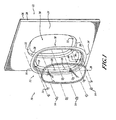
- an exemplary window frame assembly 10 includes a window frame 12 and spring clips 14.
- the window frame 12 includes a window frame body 16, and flanges 18 extend from the window frame body 16.
- the spring clips 14 are removably attachable to the flanges 18.
- a window assembly 20 may be removably retained in the window frame 12 by the spring clips 14. Details will be set forth below.
- the window frame assembly 10 can be mounted within a structure 22.
- the structure 22 is a section of a fuselage of an aircraft.
- the structure 22 suitably is an aircraft's honeycomb fuselage structure.
- the structure 22 includes an inner skin 24, such as a composite laminate inner skin, an outer skin 26, such as a composite laminate outer skin, and internal honeycomb material 28 between the inner skin 24 and the outer skin 26.
- the inner skin 24, the honeycomb material 28, and the outer skin 26 are excised, thereby defining an aperture 30 to provide visual access through the wall of the structure 22.
- the aperture 30 is smaller at the outer skin 26 - that is, less of the outer skin 26 is excised than is the honeycomb material 28 and the inner skin 24. This arrangement provides a surface 32 against which the window frame 12 can bear and bond.
- the window frame 12 suitably is a metallic or composite window frame that is sized to intimately correspond to the cutout in the honeycomb material 28 and to nest against both the inner skin 24 and the outer skin 26 (at the surface 32). All interface surfaces between the window frame 12 and the structure 22 are adhesively bonded to obtain homogenous load carrying capability through the window frame assembly 10 as well as provide a sealed barrier over the honeycomb material 28 to prevent moisture ingression.
- the window frame body 16 includes external surfaces that interface with the structure 22.
- a frame surface 34 is coincident to the surface of the cutout of the honeycomb material 28 and is bonded to the honeycomb material 28 with a suitable adhesive, like a two-part adhesive such as without limitation EA9394 paste adhesive.
- a suitable adhesive like a two-part adhesive such as without limitation EA9394 paste adhesive.
- surfaces 36 and 38 Approximately perpendicular to the surface 34 are surfaces 36 and 38.
- the surface 36 interfaces with the outer skin 26 at the surface 32 and the surface 38 interfaces with the inner skin 24.
- the same adhesive as described above suitably is applied to the surfaces 36 and 32 and to the surfaces 38 and 24 to bond them and to provide a seal against moisture.
- An interior of the surface 36 also serves as a sill 40 in which the window assembly 20 will bear against.
- the flanges 18 are substantially rectangular, upstanding projections that project from the internal side of the window frame body 16 approximately perpendicular to the inner skin 24 and the outer skin 26.
- the flanges 18 provide a means for aligning and holding the spring clips 14 that are used to retain the window assembly 20 in place against the sill 40. Any number of the flanges 18 may be provided as desired to retain the window assembly 20 in any particular application. The number of the flanges 18 that are used may depend, in part on factors such as size of the window assembly 20, size of the spring clips 14, associated loads, and the like.
- the inherent flexure in this spring attach mechanism additionally provides a means of absorbing blunt exterior impact against the window assembly 20, thereby minimizing damage to the window glazing material.
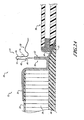
- each flange 18 provides a locking member 42 that is a means for releasably locking or engaging with the spring clip 14.
- the locking member 42 may be provided as saw tooth grooves that are defined on a face 44 of the flange 18. Another exemplary embodiment will be discussed later.
- the spring clips 14 are snapped into place over the attachment features (that is, the locking member 42) of the flanges 18 in such a manner as to hold the window assembly 20 firmly against the sill 40.
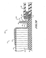
- the spring clip 14 includes an attachment portion 46 that receives therein the flange 18.
- An edge 48 may be curved, if desired, to aid in installation of the spring clip 14 over the flange 18.
- a biasing portion 50 is suitably shaped, such as by being bent downwardly towards the window assembly 20, to apply a preloaded pressure against the window assembly 20 when the spring clip 14 is fully installed and compressed.
- each spring clip 14 provides a locking member 52 that is a means for releasably locking or engaging with the flange 18.
- the locking member 52 may be provided as a pair of angled tabs that extend from a face 54 of the attachment portion 46 of the spring clip 14.
- the pair of dual angled tabs 52 retain the spring clip 14 in position against mating saw tooth grooves 42 of the flange 18. Another exemplary embodiment will be discussed later.
- the spring clips 14 are installed over the flanges 18 and are depressed against the window assembly 20 to retain the window assembly 20 in position.
- the spring clip 14 is captured in position by the use of the locking members 42 and 52.
- the pair of angled two locking tabs 52 interface or engage with the saw tooth grooves 42 on the face 44 of the flange 18.
- the tabs 52 are angled such that they will snap over the saw tooth grooves 42 during installation until the spring clip 14 is fully compressed against the window assembly 20.
- window frame assemblies disclosed herein may help reduce weight by up to around a pound or so per installed window assembly over window assemblies installed in aircraft using conventional window frame assemblies. In aircraft having hundreds of window assemblies installed therein, use of some embodiments of window frame assemblies disclosed herein may help contribute to a total weight savings of up to hundreds of pounds or so, depending on the number of installed window assemblies.
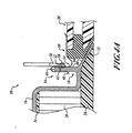
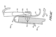
- the spring clip 14 includes a release member 56 to help in removal of the window assembly 20.
- the release member 56 may be provided in the form of a tab that is fashioned in the face 54 of the spring clip 14.
- the release member 56 such as the tab, suitably is centered between the pair of locking members 52, such as the pair of angled tabs.
- the release member 56 provides a face such that a tool 58, such as a screwdriver, can be inserted to apply a force to rotate the face 54 of the spring clip 14.
- the face 54 of the spring clip 14 is rotatably pried open by the tool 58 as shown by arrows 60 to disengage the locking members 52, such as the pair of angled tabs of the spring clip 14, from the locking members 42, such as the saw tooth grooves of the flange 18.
- the spring clip 14 Upon disengaging the locking members 52, the spring clip 14 will unload the compression load stored against the window assembly 20 and allow for removal from the flange 18. Once all of the spring clips 14 arc removed, the window assembly 20 is free to be removed.
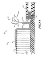
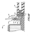
- locking members 42A and 52A are similar to the locking members 42 and 52 ( FIGURES 2 A , 2B , and 2C ), except the implementation of the type of locking members is reversed from the implementation illustrated in FIGURES 2A , 2B , and 2C .
- a flange 18A provides as locking members 42A angled tabs that extend inwardly from the face 44.
- a spring clip 14A provides saw tooth grooves 52A that extend outwardly from the face 54 (that is, away from the flange 18A). All other details of construction and operation of the window frame assembly 1OA are the same as those set forth above for the window frame assembly 10 and need not be repeated for an understanding of the embodiment.
- Like reference numbers are used to refer to the same details:
- the window assembly 20 is removed from the window frame assembly 1 OA in a similar manner as discussed above for the window frame assembly 10 ( FIGURES 4A , 4B , and 4C ).
- rotation of the face 54 of the spring clip 14A disengages the saw tooth grooves 52 A of the spring clip 14A from the tabs 42 A of the flange 18A.
- All other details of removal of the window assembly 20 from the window frame assembly 1OA are the same as those discussed above for the window frame assembly 10 ( FIGURES 4A , 4B , and 4C ) and need not be repeated.
- Like reference numbers are used to refer to the same details.
Landscapes
- Engineering & Computer Science (AREA)
- Mechanical Engineering (AREA)
- General Engineering & Computer Science (AREA)
- Aviation & Aerospace Engineering (AREA)
- Civil Engineering (AREA)
- Structural Engineering (AREA)
- Securing Of Glass Panes Or The Like (AREA)
- Connection Of Plates (AREA)
- Window Of Vehicle (AREA)
- Power-Operated Mechanisms For Wings (AREA)
Claims (7)
- Aéronef comprenant:une section d'un fuselage d'aéronef comportant une peau intérieure (24), une peau extérieure (26) et définissant une pluralité de découpures de fenêtre (30);une pluralité de châssis de fenêtre (12) reçus dans la pluralité de découpures de fenêtre, chacun de la pluralité de châssis de fenêtre comportant:un corps de châssis de fenêtre (16); etune pluralité de brides (18, 18A) s'étendant du corps de châssis de fenêtre, chacune de la pluralité de brides définissant au moins un premier élément de verrouillage (42, 42A);une pluralité de clips élastiques (14, 14A) fixés amoviblement à la pluralité de brides par la mise en prise dudit au moins un premier élément de verrouillage (42, 42A); etune pluralité d'ensembles de fenêtre (20) retenus amoviblement dans la pluralité de châssis de fenêtre (12) par la pluralité de clips élastiques (14, 14A).
- Aéronef selon la revendication 1, dans lequel chacun de la pluralité de clips élastiques définit au moins un deuxième élément de verrouillage (52, 52A) configuré pour une mise en prise avec le premier élément de verrouillage.
- Aéronef selon la revendication 2, dans lequel:le au moins un premier élément de verrouillage (42) comporte une pluralité de rainures en dents de scie; etle au moins un deuxième élément de verrouillage (52) comporte une paire de pattes angulaires.
- Aéronef selon la revendication 2, dans lequel:le au moins un premier élément de verrouillage (42A) comporte une paire de pattes angulaires; etle au moins un deuxième élément de verrouillage (52A) comporte une pluralité de rainures en dents de scie.
- Aéronef selon la revendication 1, dans lequel chacun de la pluralité de clips élastiques (14, 14A) définit en outre un mécanisme de libération (56) configuré pour sortir de prise le clip élastique et la bride (18, 18A).
- Aéronef selon la revendication 5, dans lequel le mécanisme de libération (56) comporte une patte.
- Aéronef selon la revendication 1, dans lequel la section du fuselage d'aéronef comporte un matériau en nid d'abeilles entre la peau intérieure (24) et la peau extérieure (26).
Applications Claiming Priority (2)
| Application Number | Priority Date | Filing Date | Title |
|---|---|---|---|
| US11/714,456 US7823833B2 (en) | 2007-03-05 | 2007-03-05 | Window installation method and apparatus |
| PCT/US2008/052941 WO2008109217A1 (fr) | 2007-03-05 | 2008-02-04 | Procédé d'installation de fenêtres et appareil |
Publications (2)
| Publication Number | Publication Date |
|---|---|
| EP2114764A1 EP2114764A1 (fr) | 2009-11-11 |
| EP2114764B1 true EP2114764B1 (fr) | 2011-04-06 |
Family
ID=39507962
Family Applications (1)
| Application Number | Title | Priority Date | Filing Date |
|---|---|---|---|
| EP08728951A Active EP2114764B1 (fr) | 2007-03-05 | 2008-02-04 | Appareil d'installation de fenêtres d'un aeronef |
Country Status (5)
| Country | Link |
|---|---|
| US (2) | US7823833B2 (fr) |
| EP (1) | EP2114764B1 (fr) |
| AT (1) | ATE504492T1 (fr) |
| DE (1) | DE602008006026D1 (fr) |
| WO (1) | WO2008109217A1 (fr) |
Cited By (1)
| Publication number | Priority date | Publication date | Assignee | Title |
|---|---|---|---|---|
| EP4321427A1 (fr) * | 2022-08-10 | 2024-02-14 | Airbus Operations GmbH | Structure de montage de fenêtre pour le montage par encliquetage d'un ensemble fenêtre d'un aéronef |
Families Citing this family (34)
| Publication number | Priority date | Publication date | Assignee | Title |
|---|---|---|---|---|
| WO2009008903A1 (fr) * | 2007-01-12 | 2009-01-15 | The Nordam Group, Inc. | Ecran de protection contre l'érosion de fenêtre d'aéronef |
| US20090193728A1 (en) * | 2008-01-31 | 2009-08-06 | Simonton Building Products, Inc. | Window Casing |
| US9151056B2 (en) | 2008-04-17 | 2015-10-06 | Konvin Associates, L.P. | Dual glazing panel system |
| US8056289B1 (en) * | 2008-04-17 | 2011-11-15 | Konvin Associates Ltd. | Dual glazing panel system |
| DE102009013511B4 (de) * | 2009-03-17 | 2015-05-21 | Airbus Operations Gmbh | Fensterelement für ein doppelschaliges Hautfeld einer Flugzeugrumpfzelle |
| DE102009013585B4 (de) * | 2009-03-17 | 2012-01-26 | Airbus Operations Gmbh | Rumpfzellenstruktur für ein Flugzeug in Hybridbauweise |
| US9528266B2 (en) | 2009-04-17 | 2016-12-27 | Konvin Associates, L.P. | Dual glazing panel system |
| US8550140B2 (en) * | 2009-08-31 | 2013-10-08 | Andersen Corporation | Storm window and panel attachment |
| NL2004399C2 (nl) * | 2010-03-15 | 2011-09-16 | Stichting Beheer En Toezicht Merkenrechten Rotterdam | Hulpmiddel en werkwijze voor het voorspannen van glas in een kozijn. |
| FR2959480A1 (fr) * | 2010-04-30 | 2011-11-04 | Airbus Operations Sas | Procede d'assemblage d'encadrements d'hublots sur un fuselage, encadrement de mise en oeuvre et fuselage d'aeronef equipe de tels encadrements |
| CN102869569B (zh) * | 2010-04-30 | 2015-11-25 | 空中客车运营简化股份公司 | 在机身上组装舷窗围框的方法、用于实施的围框以及配置有此类围框的飞行器机身 |
| EP2640919A4 (fr) | 2010-11-16 | 2018-01-10 | The Nordam Group, Inc. | Fabrication de cadre hybride par moulage conjoint |
| US8701260B1 (en) * | 2010-12-21 | 2014-04-22 | The Boeing Company | Removal of aircraft window reveal |
| CA2824054C (fr) * | 2011-01-13 | 2018-01-02 | Aerospace Technologies Group, Inc. | Systemes et procedes permettant d'installer un mecanisme motorise d'obturateur de hublot dans un aeronef |
| US8944381B2 (en) * | 2011-03-25 | 2015-02-03 | The Boeing Company | Aircraft window and installation method |
| US9458869B2 (en) * | 2011-05-13 | 2016-10-04 | Koninklijke Philips N.V. | Fastening element for clamping sheets |
| DE102011108167B4 (de) * | 2011-07-20 | 2014-02-13 | Airbus Operations Gmbh | Fenstertrichter sowie Fensterbereich für ein Flugzeug |
| US9221533B1 (en) | 2011-10-24 | 2015-12-29 | The Boeing Company | Removable window system for space vehicles |
| US9016629B1 (en) * | 2011-11-28 | 2015-04-28 | The Boeing Company | Combined pressure and thermal window system for space vehicles |
| EP2730497B1 (fr) * | 2012-11-13 | 2017-04-19 | Airbus Operations GmbH | Ensemble d'hublot d'aéronef |
| USD728446S1 (en) * | 2013-05-21 | 2015-05-05 | Airbus Corporate Jet Centre | Aircraft window |
| EP2842865B1 (fr) * | 2013-08-28 | 2019-12-18 | Airbus Operations GmbH | Panneau de fenêtre pour une cellule d'aéronef et son procédé de production |
| US9399507B2 (en) * | 2014-01-22 | 2016-07-26 | The Boeing Company | Joints between a composite skin and a load-bearing component and methods of forming same |
| US9340275B2 (en) | 2014-02-25 | 2016-05-17 | Textron Innovations, Inc. | Window assembly installation |
| US10112695B2 (en) * | 2015-08-20 | 2018-10-30 | Georgian Aerospace Llc | Receptacle, payload assembly and related methods for an aircraft |
| US20170051552A1 (en) | 2015-08-21 | 2017-02-23 | Deco Flash, Llc | Clip Fastener System For a Window |
| USD886013S1 (en) * | 2017-04-10 | 2020-06-02 | Volvo Lastvagnar Ab | Shade assembly for vehicle window |
| FR3065258B1 (fr) * | 2017-04-18 | 2019-06-28 | Treves Products, Services & Innovation | Systeme d’insonorisation pour moteur de vehicule automobile |
| US10309146B1 (en) | 2018-01-08 | 2019-06-04 | Deco Flash Llc | Screwless window fastening system |
| DE102018001966A1 (de) * | 2018-03-10 | 2019-09-12 | Diehl Aviation Laupheim Gmbh | Verkleidungselement, Modulsatz und Herstellungsverfahren |
| DE102018129159B4 (de) * | 2018-11-20 | 2022-12-22 | Airbus Operations Gmbh | Fensterelement mit nicht-verdeckender Blende, Flugzeugbereich und Flugzeug mit Fensterelement |
| US11407486B2 (en) * | 2019-11-14 | 2022-08-09 | The Boeing Company | Window clamp system for a vehicle |
| DE102020125610A1 (de) * | 2020-09-30 | 2022-03-31 | Premium Aerotec Gmbh | Fensterrahmen für ein Fahrzeug und Verfahren zum Herstellen eines Fensterrahmens |
| US11565811B1 (en) | 2022-01-28 | 2023-01-31 | Blended Wing Aircraft, Inc. | Blended wing body aircraft with transparent panels |
Family Cites Families (15)
| Publication number | Priority date | Publication date | Assignee | Title |
|---|---|---|---|---|
| US1073805A (en) * | 1911-02-25 | 1913-09-23 | William R Kinnear | Glass-holder for metal sash. |
| US1793127A (en) * | 1927-12-08 | 1931-02-17 | Osius Conrad | Holding means for glass |
| CH216624A (de) | 1941-02-21 | 1941-09-15 | Sueess Jost | Metallfenster. |
| US3155422A (en) | 1961-11-06 | 1964-11-03 | Gen Motors Corp | Windshield mounting |
| US4541595A (en) * | 1983-03-28 | 1985-09-17 | Heath-Tecna Precision Structures | Removable interior window unit for aircraft |
| DE3771330D1 (de) | 1987-04-21 | 1991-08-14 | Boeing Co | Fensterscheibe mit eingeschlossener kunststoff-zwischenschicht. |
| US5251418A (en) | 1991-07-17 | 1993-10-12 | The Stanley Works | Panel door frame assembly |
| US5271581A (en) * | 1992-05-29 | 1993-12-21 | Irish Michael J | Window clip for aircraft |
| US6082674A (en) * | 1998-09-16 | 2000-07-04 | Mcdonnel Douglas Corporation | Aircraft window escuthcheon assembly |
| US6786453B2 (en) * | 2001-10-25 | 2004-09-07 | The Boeing Company | Snap-in window assembly and method |
| US6793182B2 (en) * | 2002-03-25 | 2004-09-21 | The Boeing Company | Window attachment system |
| US6736352B2 (en) * | 2002-06-25 | 2004-05-18 | The Boeing Company | Aircraft windows and associated methods for installation |
| US6889938B1 (en) * | 2003-10-21 | 2005-05-10 | The Boeing Company | Structural cockpit window and method of making same |
| US7162841B2 (en) * | 2004-02-13 | 2007-01-16 | Kownacki Charles D | Spring clip and method of window installation |
| DE102004025375B4 (de) | 2004-05-24 | 2010-01-28 | Airbus Deutschland Gmbh | Fensterrahmen für Flugzeuge |
-
2007
- 2007-03-05 US US11/714,456 patent/US7823833B2/en active Active
-
2008
- 2008-02-04 WO PCT/US2008/052941 patent/WO2008109217A1/fr not_active Ceased
- 2008-02-04 AT AT08728951T patent/ATE504492T1/de not_active IP Right Cessation
- 2008-02-04 EP EP08728951A patent/EP2114764B1/fr active Active
- 2008-02-04 DE DE602008006026T patent/DE602008006026D1/de active Active
-
2010
- 2010-09-29 US US12/893,223 patent/US8087615B2/en active Active
Cited By (2)
| Publication number | Priority date | Publication date | Assignee | Title |
|---|---|---|---|---|
| EP4321427A1 (fr) * | 2022-08-10 | 2024-02-14 | Airbus Operations GmbH | Structure de montage de fenêtre pour le montage par encliquetage d'un ensemble fenêtre d'un aéronef |
| US12589855B2 (en) | 2022-08-10 | 2026-03-31 | Airbus Operations Gmbh | Window mounting structure for snap and click mounting of a window assembly of an aircraft |
Also Published As
| Publication number | Publication date |
|---|---|
| US8087615B2 (en) | 2012-01-03 |
| ATE504492T1 (de) | 2011-04-15 |
| US7823833B2 (en) | 2010-11-02 |
| US20110016823A1 (en) | 2011-01-27 |
| US20080217479A1 (en) | 2008-09-11 |
| EP2114764A1 (fr) | 2009-11-11 |
| DE602008006026D1 (de) | 2011-05-19 |
| WO2008109217A1 (fr) | 2008-09-12 |
Similar Documents
| Publication | Publication Date | Title |
|---|---|---|
| US8087615B2 (en) | Window installation method | |
| US4987699A (en) | Mounting for an automotive window panel | |
| US7108313B2 (en) | Trim assembly and method of manufacturing same | |
| CA2405923C (fr) | Hublot d'aeronef encliquetable et methode de montage | |
| US4938521A (en) | Spacer for vehicle windshield | |
| CA2953523C (fr) | Ensemble de retenue multicouche | |
| CN101291822A (zh) | 在开口之上安装面板的方法和装置 | |
| EP1748926B1 (fr) | Cadre de fenetre destine a un aeronef | |
| US6814331B2 (en) | Device for removably fastening a first part to a second part mountable in an aircraft | |
| US20080116722A1 (en) | Support Module for Vehicle Doors and Method of Mounting Same | |
| US6793182B2 (en) | Window attachment system | |
| US9482491B1 (en) | Detachable armor hold down | |
| US20070095984A1 (en) | Window assembly retaining system | |
| CN110168182A (zh) | 用于能升降的车辆-侧面玻璃的保持元件 | |
| US20050230994A1 (en) | Vehicle trim panel securement | |
| EP1462347B2 (fr) | Revêtement d'une soute de cargaison | |
| EP3529133B1 (fr) | Application d'adhésif à proportions variables | |
| WO2006046064A3 (fr) | Cadre souple et moyens de fixation pouvant s'emboiter l'un dans l'autre | |
| US11059523B2 (en) | Adjustable datum pin assembly for temporarily securing a vehicle component to a vehicle structure | |
| US7562846B2 (en) | Window retaining system | |
| GB2512073A (en) | Fixing assembly for a watershield | |
| US20190061598A1 (en) | Cargo net anchor guard | |
| EP1190942A2 (fr) | Ensemble de montage d'un toit ouvrant de véhicule |
Legal Events
| Date | Code | Title | Description |
|---|---|---|---|
| PUAI | Public reference made under article 153(3) epc to a published international application that has entered the european phase |
Free format text: ORIGINAL CODE: 0009012 |
|
| 17P | Request for examination filed |
Effective date: 20090624 |
|
| AK | Designated contracting states |
Kind code of ref document: A1 Designated state(s): AT BE BG CH CY CZ DE DK EE ES FI FR GB GR HR HU IE IS IT LI LT LU LV MC MT NL NO PL PT RO SE SI SK TR |
|
| 17Q | First examination report despatched |
Effective date: 20100210 |
|
| DAX | Request for extension of the european patent (deleted) | ||
| GRAP | Despatch of communication of intention to grant a patent |
Free format text: ORIGINAL CODE: EPIDOSNIGR1 |
|
| RTI1 | Title (correction) |
Free format text: AIRCRAFT WINDOW INSTALLATION APPARATUS |
|
| GRAS | Grant fee paid |
Free format text: ORIGINAL CODE: EPIDOSNIGR3 |
|
| GRAA | (expected) grant |
Free format text: ORIGINAL CODE: 0009210 |
|
| AK | Designated contracting states |
Kind code of ref document: B1 Designated state(s): AT BE BG CH CY CZ DE DK EE ES FI FR GB GR HR HU IE IS IT LI LT LU LV MC MT NL NO PL PT RO SE SI SK TR |
|
| REG | Reference to a national code |
Ref country code: GB Ref legal event code: FG4D |
|
| REG | Reference to a national code |
Ref country code: CH Ref legal event code: EP |
|
| REG | Reference to a national code |
Ref country code: IE Ref legal event code: FG4D |
|
| REF | Corresponds to: |
Ref document number: 602008006026 Country of ref document: DE Date of ref document: 20110519 Kind code of ref document: P |
|
| REG | Reference to a national code |
Ref country code: DE Ref legal event code: R096 Ref document number: 602008006026 Country of ref document: DE Effective date: 20110519 |
|
| REG | Reference to a national code |
Ref country code: NL Ref legal event code: VDEP Effective date: 20110406 |
|
| PG25 | Lapsed in a contracting state [announced via postgrant information from national office to epo] |
Ref country code: SI Free format text: LAPSE BECAUSE OF FAILURE TO SUBMIT A TRANSLATION OF THE DESCRIPTION OR TO PAY THE FEE WITHIN THE PRESCRIBED TIME-LIMIT Effective date: 20110406 |
|
| LTIE | Lt: invalidation of european patent or patent extension |
Effective date: 20110406 |
|
| PG25 | Lapsed in a contracting state [announced via postgrant information from national office to epo] |
Ref country code: HR Free format text: LAPSE BECAUSE OF FAILURE TO SUBMIT A TRANSLATION OF THE DESCRIPTION OR TO PAY THE FEE WITHIN THE PRESCRIBED TIME-LIMIT Effective date: 20110406 Ref country code: SE Free format text: LAPSE BECAUSE OF FAILURE TO SUBMIT A TRANSLATION OF THE DESCRIPTION OR TO PAY THE FEE WITHIN THE PRESCRIBED TIME-LIMIT Effective date: 20110406 Ref country code: PT Free format text: LAPSE BECAUSE OF FAILURE TO SUBMIT A TRANSLATION OF THE DESCRIPTION OR TO PAY THE FEE WITHIN THE PRESCRIBED TIME-LIMIT Effective date: 20110808 Ref country code: LT Free format text: LAPSE BECAUSE OF FAILURE TO SUBMIT A TRANSLATION OF THE DESCRIPTION OR TO PAY THE FEE WITHIN THE PRESCRIBED TIME-LIMIT Effective date: 20110406 Ref country code: NO Free format text: LAPSE BECAUSE OF FAILURE TO SUBMIT A TRANSLATION OF THE DESCRIPTION OR TO PAY THE FEE WITHIN THE PRESCRIBED TIME-LIMIT Effective date: 20110706 |
|
| PG25 | Lapsed in a contracting state [announced via postgrant information from national office to epo] |
Ref country code: FI Free format text: LAPSE BECAUSE OF FAILURE TO SUBMIT A TRANSLATION OF THE DESCRIPTION OR TO PAY THE FEE WITHIN THE PRESCRIBED TIME-LIMIT Effective date: 20110406 Ref country code: LV Free format text: LAPSE BECAUSE OF FAILURE TO SUBMIT A TRANSLATION OF THE DESCRIPTION OR TO PAY THE FEE WITHIN THE PRESCRIBED TIME-LIMIT Effective date: 20110406 Ref country code: BE Free format text: LAPSE BECAUSE OF FAILURE TO SUBMIT A TRANSLATION OF THE DESCRIPTION OR TO PAY THE FEE WITHIN THE PRESCRIBED TIME-LIMIT Effective date: 20110406 Ref country code: CY Free format text: LAPSE BECAUSE OF FAILURE TO SUBMIT A TRANSLATION OF THE DESCRIPTION OR TO PAY THE FEE WITHIN THE PRESCRIBED TIME-LIMIT Effective date: 20110406 Ref country code: GR Free format text: LAPSE BECAUSE OF FAILURE TO SUBMIT A TRANSLATION OF THE DESCRIPTION OR TO PAY THE FEE WITHIN THE PRESCRIBED TIME-LIMIT Effective date: 20110707 Ref country code: AT Free format text: LAPSE BECAUSE OF FAILURE TO SUBMIT A TRANSLATION OF THE DESCRIPTION OR TO PAY THE FEE WITHIN THE PRESCRIBED TIME-LIMIT Effective date: 20110406 Ref country code: IS Free format text: LAPSE BECAUSE OF FAILURE TO SUBMIT A TRANSLATION OF THE DESCRIPTION OR TO PAY THE FEE WITHIN THE PRESCRIBED TIME-LIMIT Effective date: 20110806 Ref country code: ES Free format text: LAPSE BECAUSE OF FAILURE TO SUBMIT A TRANSLATION OF THE DESCRIPTION OR TO PAY THE FEE WITHIN THE PRESCRIBED TIME-LIMIT Effective date: 20110717 |
|
| PG25 | Lapsed in a contracting state [announced via postgrant information from national office to epo] |
Ref country code: NL Free format text: LAPSE BECAUSE OF FAILURE TO SUBMIT A TRANSLATION OF THE DESCRIPTION OR TO PAY THE FEE WITHIN THE PRESCRIBED TIME-LIMIT Effective date: 20110406 |
|
| PG25 | Lapsed in a contracting state [announced via postgrant information from national office to epo] |
Ref country code: CZ Free format text: LAPSE BECAUSE OF FAILURE TO SUBMIT A TRANSLATION OF THE DESCRIPTION OR TO PAY THE FEE WITHIN THE PRESCRIBED TIME-LIMIT Effective date: 20110406 Ref country code: EE Free format text: LAPSE BECAUSE OF FAILURE TO SUBMIT A TRANSLATION OF THE DESCRIPTION OR TO PAY THE FEE WITHIN THE PRESCRIBED TIME-LIMIT Effective date: 20110406 |
|
| PLBE | No opposition filed within time limit |
Free format text: ORIGINAL CODE: 0009261 |
|
| STAA | Information on the status of an ep patent application or granted ep patent |
Free format text: STATUS: NO OPPOSITION FILED WITHIN TIME LIMIT |
|
| PG25 | Lapsed in a contracting state [announced via postgrant information from national office to epo] |
Ref country code: PL Free format text: LAPSE BECAUSE OF FAILURE TO SUBMIT A TRANSLATION OF THE DESCRIPTION OR TO PAY THE FEE WITHIN THE PRESCRIBED TIME-LIMIT Effective date: 20110406 Ref country code: RO Free format text: LAPSE BECAUSE OF FAILURE TO SUBMIT A TRANSLATION OF THE DESCRIPTION OR TO PAY THE FEE WITHIN THE PRESCRIBED TIME-LIMIT Effective date: 20110406 Ref country code: DK Free format text: LAPSE BECAUSE OF FAILURE TO SUBMIT A TRANSLATION OF THE DESCRIPTION OR TO PAY THE FEE WITHIN THE PRESCRIBED TIME-LIMIT Effective date: 20110406 Ref country code: SK Free format text: LAPSE BECAUSE OF FAILURE TO SUBMIT A TRANSLATION OF THE DESCRIPTION OR TO PAY THE FEE WITHIN THE PRESCRIBED TIME-LIMIT Effective date: 20110406 |
|
| 26N | No opposition filed |
Effective date: 20120110 |
|
| REG | Reference to a national code |
Ref country code: DE Ref legal event code: R097 Ref document number: 602008006026 Country of ref document: DE Effective date: 20120110 |
|
| PG25 | Lapsed in a contracting state [announced via postgrant information from national office to epo] |
Ref country code: MC Free format text: LAPSE BECAUSE OF NON-PAYMENT OF DUE FEES Effective date: 20120229 |
|
| REG | Reference to a national code |
Ref country code: CH Ref legal event code: PL |
|
| PG25 | Lapsed in a contracting state [announced via postgrant information from national office to epo] |
Ref country code: CH Free format text: LAPSE BECAUSE OF NON-PAYMENT OF DUE FEES Effective date: 20120229 Ref country code: LI Free format text: LAPSE BECAUSE OF NON-PAYMENT OF DUE FEES Effective date: 20120229 |
|
| REG | Reference to a national code |
Ref country code: IE Ref legal event code: MM4A |
|
| PG25 | Lapsed in a contracting state [announced via postgrant information from national office to epo] |
Ref country code: IE Free format text: LAPSE BECAUSE OF NON-PAYMENT OF DUE FEES Effective date: 20120204 |
|
| PG25 | Lapsed in a contracting state [announced via postgrant information from national office to epo] |
Ref country code: BG Free format text: LAPSE BECAUSE OF FAILURE TO SUBMIT A TRANSLATION OF THE DESCRIPTION OR TO PAY THE FEE WITHIN THE PRESCRIBED TIME-LIMIT Effective date: 20110706 |
|
| PG25 | Lapsed in a contracting state [announced via postgrant information from national office to epo] |
Ref country code: MT Free format text: LAPSE BECAUSE OF FAILURE TO SUBMIT A TRANSLATION OF THE DESCRIPTION OR TO PAY THE FEE WITHIN THE PRESCRIBED TIME-LIMIT Effective date: 20110406 |
|
| PG25 | Lapsed in a contracting state [announced via postgrant information from national office to epo] |
Ref country code: TR Free format text: LAPSE BECAUSE OF FAILURE TO SUBMIT A TRANSLATION OF THE DESCRIPTION OR TO PAY THE FEE WITHIN THE PRESCRIBED TIME-LIMIT Effective date: 20110406 |
|
| PG25 | Lapsed in a contracting state [announced via postgrant information from national office to epo] |
Ref country code: LU Free format text: LAPSE BECAUSE OF NON-PAYMENT OF DUE FEES Effective date: 20120204 |
|
| PG25 | Lapsed in a contracting state [announced via postgrant information from national office to epo] |
Ref country code: HU Free format text: LAPSE BECAUSE OF FAILURE TO SUBMIT A TRANSLATION OF THE DESCRIPTION OR TO PAY THE FEE WITHIN THE PRESCRIBED TIME-LIMIT Effective date: 20080204 |
|
| REG | Reference to a national code |
Ref country code: FR Ref legal event code: PLFP Year of fee payment: 9 |
|
| REG | Reference to a national code |
Ref country code: FR Ref legal event code: PLFP Year of fee payment: 10 |
|
| REG | Reference to a national code |
Ref country code: FR Ref legal event code: PLFP Year of fee payment: 11 |
|
| P01 | Opt-out of the competence of the unified patent court (upc) registered |
Effective date: 20230516 |
|
| PGFP | Annual fee paid to national office [announced via postgrant information from national office to epo] |
Ref country code: GB Payment date: 20260227 Year of fee payment: 19 |
|
| PGFP | Annual fee paid to national office [announced via postgrant information from national office to epo] |
Ref country code: DE Payment date: 20260227 Year of fee payment: 19 |
|
| PGFP | Annual fee paid to national office [announced via postgrant information from national office to epo] |
Ref country code: IT Payment date: 20260219 Year of fee payment: 19 |
|
| PGFP | Annual fee paid to national office [announced via postgrant information from national office to epo] |
Ref country code: FR Payment date: 20260225 Year of fee payment: 19 |