EP2115529B1 - Brillen mit lichtquellen zur beleuchtung eines durch das brillenglas betrachteten objekts und entsprechende bügel - Google Patents
Brillen mit lichtquellen zur beleuchtung eines durch das brillenglas betrachteten objekts und entsprechende bügel Download PDFInfo
- Publication number
- EP2115529B1 EP2115529B1 EP08751464A EP08751464A EP2115529B1 EP 2115529 B1 EP2115529 B1 EP 2115529B1 EP 08751464 A EP08751464 A EP 08751464A EP 08751464 A EP08751464 A EP 08751464A EP 2115529 B1 EP2115529 B1 EP 2115529B1
- Authority
- EP
- European Patent Office
- Prior art keywords
- earpiece
- switch
- semi
- cartridge
- section
- Prior art date
- Legal status (The legal status is an assumption and is not a legal conclusion. Google has not performed a legal analysis and makes no representation as to the accuracy of the status listed.)
- Not-in-force
Links
Images

Classifications
-
- G—PHYSICS
- G02—OPTICS
- G02C—SPECTACLES; SUNGLASSES OR GOGGLES INSOFAR AS THEY HAVE THE SAME FEATURES AS SPECTACLES; CONTACT LENSES
- G02C11/00—Non-optical adjuncts; Attachment thereof
- G02C11/04—Illuminating means
Definitions
- the present invention relates in general to spectacles with light sources for illuminating an object observed through the lens and in particular to earpieces of a spectacles frame incorporating a lighting device.
- CN 20061032873 discloses spectacles with LED incorporated in the front frame and in the earpieces.
- CN 2906672Y Y discloses spectacles with LEDs incorporated in the front frame with earpieces, a part of which hinged to the front mask is hollow and accommodates a LED and related electrical hardware including a slider switch.
- the other part of the earpiece that plugs into the first part contains a powering battery.
- GB-2411009 discloses spectacles with lighting LEDs installed at the front end of the earpieces as well as on the central bridge piece of the front frame of the spectacle.
- the earpieces contain a battery and a switch for turning on /off the LEDs and a jack or inductor coil for recharging the battery.
- US-2003-086053 discloses lighting LED modules that may be mounted onto the earpieces of the spectacles.
- WO 2007/008062 A1 discloses spectacles with light sources.
- a button type powering battery is introduced inside a slot cavity defined within the thickness of the earpiece that also includes a slider switch for turning on and off the battery powered LED.
- the LED are installed at the front end of the earpieces or in the front mask of the spectacles, in the latter case by realizing isolated sliding contacts within the connecting hinge.
- the miniaturized slider switches that is normally incorporated in the earpiece is difficult to locate and operate by relying on tactile sense while wearing the spectacles.
- the enlarging of the earpieces as far as necessary to accommodate the powering battery, the switch and the electrical hardware and connecting wing to the front LED makes the general aspect of the worn eyeglasses not so pleasant.
- Fabrication of the earpieces and the realization at their interior of the electrical powering circuit of one or more LEDs is according to the known approaches rather laborious and costly.
- a single light source is incorporated or mounted at the front end of the earpiece while the powering battery of the light source and a switch are accommodated in a terminal distal portion of the earpiece, substantially beyond the point of rest of the earpiece on the ear of the wearer of the spectacles, of enlarged cross section compared to the cross section of the front and proximal part of the earpiece.
- the extra weight of the powering module is born mainly by the ears, practically relieving from it the more sensible nose of the bearer.
- turning on and off the light source is effected through a switch, the control stem of which projects from the end surface of the earpiece, to be immediately felt by the finger of the bearer and easily operated.
- a further aspect of the present invention consists in that the connecting wires of the frontally installed light source to the electrical powering circuit components housed at the farther or distal end of the earpiece, run inside part of the earpiece having a box-like hollow structure composed by two channel cross section elements or semi-earpiece joined together.
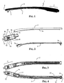
- the front and a proximal part of the earpiece 1 has a box-like structure resulting by joining channel cross section relatively slender semi-earpieces 2 and 3 and a distal part 4 of enlarged cross section compared to the front and proximal part of the earpiece.
- a holed wing 5 which will eventually be engaged in a common fastening hinge of the earpiece to a front frame of the spectacles (not depicted in the Figure).
- a light source is accommodated and retained in a front end recess defined by coupling together two channel-cross section semi-earpieces 2 and 3.
- a light source typically a LED, in Figure 1 is observable only the terminal lens 6.
- the two channel cross section semi-earpieces 2 and 3 may be better observed and so is the geometry of the coupling perimeters provided with moldings 2a and 2b and 2c that are destined to engage themselves in specularly formed channels or recesses formed along the coupling perimeter of the other semi-earpiece 3, which has a median longitudinal stiffening rib 3a the crest molding of which engages in a corresponding longitudinal recess formed along the crest of a corresponding longitudinal median rib formed in the first semi-earpiece 2, such that upon coupling together the two pieces, the inner space of the so-defined box-like structure is longitudinally divided, for a good portion of the length of the earpiece, in two distinct channels.
- the median longitudinal ribs present along both channel cross section semi-earpieces 2 and 3 confer to the resulting hollow body an enhanced rigidity.
- the distal end portion of the two semi-earpieces 2 and 3 is shaped such to confer to the distal end of this part of the earpiece of box-like structure a cross section that gradually increases as far as matching without any substantial discontinuity the enlarged cylindrical cross section of the distal part of the earpiece 4 which, in the illustrated example, comprises a cylindrical cartridge of aluminum or other light weight electrically conducting metallic material composed by telescopically screwing together two parts: respectfully a coupling end part 4a and an end or closing part 4b.
- the coupling end part 4a has a central tail 4c transversed by a hole 7 for receiving a blocking pin passed across the tailed portion 4c, after having introduced it inside an end receptacle defined by the two semi-earpieces 2 and 3 joined together and at least the wall of one or of both the two semi-earpieces, according to common assembling practices.
- the cartridge 4 contains at least one, in the depicted example two, button type batteries B in series held by a metal spring 9 that establishes also the electrical connection between the positive terminal (+) of the series of two batteries B to a first lead 10 of a push-button switch 11, a second lead 12 of which is bent in order to establishing electrical contact with the metal cartridge 4 itself.
- the control stem 13 of the switch emerges through an opening of the end face 14 of the distal cartridge part 4 of the earpiece 1.
- a common O-ring 15 stops and sustains in position the switch 11.
- Figures 3 and 4 show the end cartridge 4 respectfully associated to one and to the other of the two semi-earpieces 2 and 3 that compose the box-like front and proximal part of the earpiece.
- FIG 4 that shows the terminal cartridge 4 and the semi-earpiece 3 may be observed the front end LED 16, held between the tongued ends of the two semi-earpieces, and the pair of connecting wires respectively running in the two channels defined in the interior of the box-like structure of the earpiece.
- the wire 17 connects the respective lead of the LED 16 to the metallic bulk of the cylindrical cartridge 4 that is short circuited through the switch 11 to the positive pole of the series of two button batteries B by the bent lead 12.
- the other wire 18, optionally provided with an isolating sleeve passes through a longitudinal hole purposely formed in the tail 4c and establish an electric contact with the negative pole of the series of batteries B.
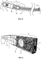
- FIGS 6 , 7 and 8 are schematic views in transparency of an earpiece of the present invention according to an alternative embodiment employing a single button battery B and a switch 11 of the so-called slider type instead of a push button switch of the prior embodiment and further implementing a different way of establishing the electrical connection between the powering and control elements contained at the free or distal end of the earpiece and a LED incorporated at the front end of the earpiece.
- the earpiece 1 of thermoplastic material may be formed in a mold in a substantially "monolithic" form, such to incorporate in the molded resin the front LED (which of course will only be partially encapsulated in the molded resin), a pair of conducting wires 17 and 18 for the powering of the LED 16 and two semi contacts 17a and 18a, to which the ends of the two wires 17 and 18 are connected.
- the semi contacts 17a and 18a are partially embedded in the resin at the bottom of the cavity of a hollow portion of enlarged cross section 1a of the molded earpiece.
- a plug-in part 4 that is eventually inserted in side the cavity of the hollow portion 1a of the molded resin earpiece is a pre-constituted assembly or module, the portion of which that is received into the end cavity of the molded earpiece has on its lead surface two semi contacts 17b and 18b that establish electric contacts with the respective partially embedded terminations 17a and 18a of the pair of conducting wires incorporated in the molded resin.
- a secure electrical contact between the two pairs of semi contacts 17a-17b and 18a-18b may be ensured by making the pair of semi contacts 17a and 18a of termination of the respective wires 17 and 18 incorporated in the molded resin of a ferromagnetic metallic material and the pair of semi contacts 17b and 18b with permanent magnets of an electrical conducting material.
- the magnetic attraction force beside ensuring a stable electrical contact also retains the pre-assembled module 4 once it is pushed fully inside the end cavity of the molded earpiece.
- the pre-constituted end module 4 adapted to be at least partly received inside the end cavity of the molded earpiece houses a button battery B, the negative pole (-) of which is connected to the semi-contact 18b.
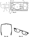
- the positive pole (+) is connected to the common lead of a slider switch 11, while the "output" lead 12 of the switch 11 is electrically connected to the semi-contact 17b on the lead surface of the plug-in module 4 pushed inside in the cavity, as shown in Figure 9 .
- a shell 1b of the same plastic material with which is formed the molded front and proximal part of the earpiece 11 encapsulates the switch 11, the relative connecting leads or pins 10 and 12 and the plastic housing of the battery B and of the semi contacts 17b and 18b, letting protrude through a narrow slot 14 present on the terminal surface of the shell 1b, the control stem 13 of the slider switch 11.
- a secure electrical contact between the semi contacts pairs 17a-17b and 18a-18b may be ensured by making the pair of semi contacts 17b and 18b in the form of mobile metallic buttons with biasing springs, installed in respective cavities of the plastic housing of the battery.
- the retention of the module 4 plugged inside the end cavity of the molded front and proximal parts of the earpiece may be ensured by common snap-action moldings or tonguings that are forcibly engaged exploiting the elastic memory of the cooperating geometric details formed in the molded material of which is made at least one of the two joinable parts, according to common practices of pre-arrangement of lockable features in separable parts of an assembled piece.
- Figures 10 and 11 are photographic rendering of spectacles of the present invention employing earpieces according to the embodiment of Figure 1-5 .
- the battery or series of batteries used as sources of electrical energy for powering the light source may be primary batteries, replaceable upon exhaustion, or alternatively they may be rechargeable batteries.
- a common jack for connection to an external battery charger or an embedded coil (secondary of an air transformer) and relative battery charging circuit powerable in a "contactless” fashion by an external device having a coil (primary of an air transformer) driven at high frequency mutually coupled to the embedded coil, according to common practices of contactless recharging of an embedded rechargeable battery of the earpiece.
Landscapes
- Physics & Mathematics (AREA)
- Health & Medical Sciences (AREA)
- General Physics & Mathematics (AREA)
- Ophthalmology & Optometry (AREA)
- Optics & Photonics (AREA)
- Eyeglasses (AREA)
Claims (12)
- Brille, die Lichtquellen (16) zur Beleuchtung eines Objekts, das durch das Brillenglas der Brille betrachtet wird, ein vorderes Brillengestell, eine Versorgungsschaltung, eine Batterie (B), einen Ein-/Aus-Schalter (11) und Bügel (1) aufweist, die mit dem vorderen Brillengestell gelenkig verbunden sind, dadurch gekennzeichnet, daß
jeder Bügel an seinem freien distalen Ende ein vorgebildetes abnehmbares Modul oder Einsatz (4) mit einer bestimmten Querschnittsgröße aufweist, das die Batterie (B), den Schalter (11) und elektrische Verbindungsmittel enthält und eine distale Endfläche mit einer Öffnung, aus der ein Bedienungsstift (13) des Schalters (11) vorsteht, und ein Hinterteil aufweist, das eingerichtet ist, in einen distalen Hohlraum eines vorderen und proximalen Teils des Bügels (1) aufgenommen zu werden;
ein elektrisches Versorgungsleitungspaar (17, 18) mindestens einer Lichtquelle (16), die am vorderen Ende des Bügels (1) vorhanden ist, wobei sich die Leitungen innerhalb des vorderen und proximalen Teils des Bügels erstrecken, wobei der vordere und proximale Teil des Bügels einen Querschnitt aufweist, der allmählich zunimmt, bis er dem Querschnitt des abnehmbaren Moduls oder Einsatzes (4) entspricht, wobei die Leitungen mit einem Anschluß der Batterie und einem Anschluß des Schalters (11) verbunden sind, der im abnehmbaren Modul oder Einsatz (4) enthalten ist. - Brille nach Anspruch 1, wobei der vordere und proximale Teil der Bügel (1) eine kastenförmige Struktur aufweist, die zwei Elemente (2, 3) mit einem kanalförmigen Querschnitt aufweist, die miteinander verbunden sind, um mindestens einen Leitungskanal zu definieren, innerhalb dessen das elektrische Versorgungsleitungspaar (17, 18) einer LED (16) verläuft, die am vorderen Ende des Bügels (1) gehalten wird, wobei die Elemente (2, 3) einen Querschnitt aufweisen, der allmählich zunimmt, bis er dem Querschnitt des abnehmbaren Moduls oder Einsatzes (4) entspricht.
- Brille nach Anspruch 2, wobei der abnehmbare Einsatz (4) metallisch ist und aus einem ersten Halbeinsatz (4a), der ein Hinterteil (4c) aufweist, das in den distalen Hohlraum des kastenförmigen vorderen und proximalen Teils des Bügels einsetzbar ist, der durch zwei miteinander verbundene Elemente (2, 3) gebildet wird, und aus einem zweiten Halbeinsatz (4b) zusammengesetzt ist, der an den ersten Halbeinsatz (4a) geschraubt ist und eine Öffnung durch seine Endfläche (14) aufweist, durch die ein Bedienungsstift (13) des Schalters (11) vorsteht.
- Brille nach Anspruch 1, wobei der vordere und proximale Teil des Bügels in einer monolithischen Form hergestellt ist, die in einem distalen Teil mit allmählich zunehmenden Querschnitt den Hohlraum definiert, der eingerichtet ist, ein vorgebildetes Modul (4) aufzunehmen, das die Batterie (B), den Schalter (11) und elektrische Verbindungsmittel enthält, das teilweise durch eine Endhülse (1b) mit einer Öffnung umhüllt ist, durch die ein Bedienungsstift des Schalters vorsteht;
wobei die elektrischen Verbindungsmittel ein Halbkontaktpaar (17b, 18b) aufweisen, das eingerichtet ist, jeweilige Anschlußhalbkontakte (17a, 18a) des Versorgungsleitungspaars (17, 18) der Lichtquelle (16) zu kontaktieren, das teilweise am Boden des Hohlraums im Material des ausgebildeten monolithischen vorderen und proximalen Teils des Bügels eingelassen ist. - Brille nach Anspruch 4, wobei der elektrische Kontakt zwischen den Halbkontaktpaaren (17a, 18a, 17b, 18b) durch Vorspannfedern sichergestellt wird, die auf Halbkontakte wirken, die an der Endfläche des Eingesteckmoduls (4) vorhanden sind, das in den Hohlraum eingeführt und arretiert ist.
- Brille nach Anspruch 4, wobei der elektrische Kontakt zwischen den Halbkontaktpaaren sichergestellt wird, indem das Anschlußhalbkontaktpaar (17a, 18a) mit einem ferromagnetischen metallischen Material und das an der Endfläche des Eingesteckmoduls (4) vorhandene Halbkontaktpaar (17b, 18b) mit zwei Permanentmagneten aus einem elektrisch leitenden Material hergestellt sind.
- Bügel (1) für eine Brille, der eine Lichtquelle (16) an seinem vorderen Ende, eine Batterie (B), einen Schalter (11) und elektrische Verbindungsmittel zur Versorgung der Lichtquelle aufweist, dadurch gekennzeichnet, daß er aufweist
ein vorgebildetes abnehmbares Modul oder Einsatz (4) mit einer bestimmten Querschnittsgröße, das die Batterie (B), den Schalter (11) und elektrische Verbindungsmittel enthält und eine distale Endfläche mit einer Öffnung, aus der ein Bedienungsstift (13) des Schalters (11) vorsteht, und ein Hinterteil aufweist, das eingerichtet ist, in einen distalen Hohlraum eines vorderen und proximalen Teils des Bügels (1) aufgenommen zu werden;
ein elektrisches Versorgungsleitungspaar (17, 18) der Lichtquelle (16), die am vorderen Ende des Bügels (1) vorhanden ist, wobei sich die Leitungen innerhalb des vorderen und proximalen Teils des Bügels erstrecken, wobei der vordere und proximale Teil des Bügels einen Querschnitt aufweist, der allmählich zunimmt, bis er dem Querschnitt des abnehmbaren Moduls oder Einsatzes (4) entspricht, wobei die Leitungen mit einem Anschluß der Batterie und einem Anschluß des Schalters (11) verbunden sind, der im abnehmbaren Modul oder Einsatz (4) enthalten ist. - Bügel nach Anspruch 7, dadurch gekennzeichnet, daß der vordere und proximale Teil eine kastenförmige Struktur aufweist, die aus zwei Elementen (2, 3) mit einem kanalförmigen Querschnitt zusammengesetzt ist, die miteinander verbunden sind, um mindestens einen Leitungskanal zu definieren, innerhalb dessen sich die elektrischen Versorgungsleitungen (17, 18) einer LED (16) erstrecken, die am vorderen Ende gehalten wird.
- Bügel nach Anspruch 8, wobei der Einsatz metallisch ist und aus einem ersten Halbeinsatz mit einem Hinterteil, das eingerichtet ist, in einen distalen Hohlraum des kastenförmig strukturierten Teil des Bügels eingesetzt zu werden, der durch zwei miteinander verbundene Elemente (2, 3) gebildet wird, und aus einem zweiten Halbeinsatz zusammengesetzt ist, der an den ersten Halbeinsatz geschraubt ist und eine Öffnung durch seine distale Endfläche aufweist, durch die ein Bedienungsstift des Schalters vorsteht.
- Bügel nach Anspruch 7, wobei der vordere und proximale Teil des Bügels (1) in einer monolithischen Form hergestellt ist, die in einem distalen Teil mit allmählich zunehmenden Querschnitt den Hohlraum definiert, der eingerichtet ist, ein vorgebildetes Modul (4) aufzunehmen, das teilweise durch eine Endhülse (1b) mit einer Öffnung umhüllt ist, durch die ein Bedienungsstift des Schalters vorsteht, das die Batterie (B), den Schalter (11) und elektrische Verbindungsmittel enthält;
wobei die elektrischen Verbindungsmittel ein Halbkontaktpaar (17b, 18b) aufweisen, das eingerichtet ist, jeweilige Anschlußhalbkontakte (17a, 18a) des Versorgungsleitungspaars (17, 18) der Lichtquelle (16) zu kontaktieren, das teilweise am Boden des Hohlraums im Material des ausgebildeten monolithischen vorderen und proximalen Teils des Bügels (1) eingelassen ist. - Bügel nach Anspruch 10, wobei der elektrische Kontakt zwischen den Halbkontaktpaaren (17a, 18a, 17b, 18b) durch Vorspannfedern sichergestellt wird, die auf beweglich gehaltene Halbkontakte (17b, 18b) wirken, die an der Endfläche des Eingesteckmoduls (4) vorhanden sind, das in den Hohlraum eingeführt und arretiert ist.
- Bügel nach Anspruch 10, wobei der elektrische Kontakt zwischen den Halbkontaktpaaren (17a, 18a, 17b, 18b) sichergestellt wird, indem das Anschlußhalbkontaktpaar (17a, 18a) mit einem ferromagnetischen metallischen Material und das an der Endfläche des Eingesteckmoduls (4) vorhandene Halbkontaktpaar (17b, 18b) mit zwei Permanentmagneten aus einem elektrisch leitenden Material hergestellt sind.
Applications Claiming Priority (1)
| Application Number | Priority Date | Filing Date | Title |
|---|---|---|---|
| PCT/IT2008/000069 WO2009098719A1 (en) | 2008-02-05 | 2008-02-05 | Spectacles with light sources for illuminating an object observed through the lens and related earpieces |
Publications (2)
| Publication Number | Publication Date |
|---|---|
| EP2115529A1 EP2115529A1 (de) | 2009-11-11 |
| EP2115529B1 true EP2115529B1 (de) | 2012-04-18 |
Family
ID=39719048
Family Applications (1)
| Application Number | Title | Priority Date | Filing Date |
|---|---|---|---|
| EP08751464A Not-in-force EP2115529B1 (de) | 2008-02-05 | 2008-02-05 | Brillen mit lichtquellen zur beleuchtung eines durch das brillenglas betrachteten objekts und entsprechende bügel |
Country Status (4)
| Country | Link |
|---|---|
| US (1) | US20110058141A1 (de) |
| EP (1) | EP2115529B1 (de) |
| AT (1) | ATE554421T1 (de) |
| WO (1) | WO2009098719A1 (de) |
Families Citing this family (23)
| Publication number | Priority date | Publication date | Assignee | Title |
|---|---|---|---|---|
| US11061252B2 (en) | 2007-05-04 | 2021-07-13 | E-Vision, Llc | Hinge for electronic spectacles |
| US8783861B2 (en) | 2010-07-02 | 2014-07-22 | Pixeloptics, Inc. | Frame design for electronic spectacles |
| US8801174B2 (en) | 2011-02-11 | 2014-08-12 | Hpo Assets Llc | Electronic frames comprising electrical conductors |
| US8979259B2 (en) | 2010-07-02 | 2015-03-17 | Mitsui Chemicals, Inc. | Electro-active spectacle frames |
| US8905541B2 (en) | 2010-07-02 | 2014-12-09 | Mitsui Chemicals, Inc. | Electronic spectacle frames |
| US10613355B2 (en) | 2007-05-04 | 2020-04-07 | E-Vision, Llc | Moisture-resistant eye wear |
| US12572035B2 (en) | 2007-05-04 | 2026-03-10 | E-Vision Optics, Llc | Moisture-resistant eye wear |
| US8944590B2 (en) | 2010-07-02 | 2015-02-03 | Mitsui Chemicals, Inc. | Electronic spectacle frames |
| BRPI1007206A2 (pt) * | 2009-01-09 | 2016-02-23 | Pixeloptics Inc | óculos eletroa-ativo e eletrônica associada |
| US12436411B2 (en) | 2010-07-02 | 2025-10-07 | E-Vision Optics, Llc | Moisture-resistant eye wear |
| GB2484285A (en) * | 2010-10-04 | 2012-04-11 | Sun And Young Optical Technology Co Ltd | Rechargeable illuminated eyeglasses |
| WO2012068527A2 (en) * | 2010-11-19 | 2012-05-24 | Pixeloptics, Inc. | Electronic spectacle frames |
| US12510773B2 (en) | 2011-02-11 | 2025-12-30 | E-Vision Optics, Llc | Moisture-resistant eye wear |
| CA2844986A1 (en) | 2011-08-17 | 2013-02-21 | Pixeloptics, Inc. | Moisture-resistant electronic spectacle frames |
| US9482883B1 (en) | 2015-04-15 | 2016-11-01 | Snapchat, Inc. | Eyewear having linkage assembly between a temple and a frame |
| US9482882B1 (en) | 2015-04-15 | 2016-11-01 | Snapchat, Inc. | Eyewear having selectively exposable feature |
| US9726904B1 (en) * | 2015-09-29 | 2017-08-08 | Snap Inc. | Eyewear with conductive temple joint |
| US10768443B2 (en) | 2015-12-22 | 2020-09-08 | Mitsui Chemicals, Inc. | Electronic eyeglasses |
| DE102017127115B4 (de) | 2017-07-28 | 2025-01-30 | Taiwan Semiconductor Manufacturing Co., Ltd. | Statischer Direkzugriffspeicher mit einer Schreibunterstützungsschaltung |
| US10734066B2 (en) | 2017-07-28 | 2020-08-04 | Taiwan Semiconductor Manufacturing Co., Ltd. | Static random access memory with write assist circuit |
| US11219287B1 (en) | 2017-08-28 | 2022-01-11 | Snap Inc. | Eyewear device charging case |
| US10847016B1 (en) * | 2019-09-11 | 2020-11-24 | Tatiana De Jesus | Eyeglasses with finder |
| CN113885204B (zh) * | 2021-10-07 | 2022-07-12 | 北京蜂巢世纪科技有限公司 | 一种智能眼镜及其制造方法 |
Citations (1)
| Publication number | Priority date | Publication date | Assignee | Title |
|---|---|---|---|---|
| US3883701A (en) * | 1971-03-18 | 1975-05-13 | Anthony Delorenzo | Eyeglass frame with hearing aid |
Family Cites Families (8)
| Publication number | Priority date | Publication date | Assignee | Title |
|---|---|---|---|---|
| GB2127254A (en) * | 1982-08-21 | 1984-04-04 | James Heaney | Hearing aid |
| DE10117446B4 (de) * | 2001-04-06 | 2007-01-04 | Optik Sommer | Modulares Beleuchtungssystem, Traggestell und Leuchtmitteleinheit dafür |
| US7581833B2 (en) * | 2003-10-09 | 2009-09-01 | Ipventure, Inc. | Eyewear supporting after-market electrical components |
| NL1029496C1 (nl) * | 2005-07-12 | 2007-01-15 | Adrianus Speekenbrink | Brilmontuur met voorzieningen voor het verlichten van objecten. |
| US20070200998A1 (en) * | 2006-02-24 | 2007-08-30 | Chemical Light, Inc. | Led illuminated novelty glasses |
| DE102006015334B4 (de) * | 2006-04-03 | 2010-11-25 | Ching-Hui Lee | Brille mit eigener Bleuchtung |
| US20080100792A1 (en) * | 2006-10-27 | 2008-05-01 | Blum Ronald D | Universal endpiece for spectacle temples |
| US7699486B1 (en) * | 2007-10-29 | 2010-04-20 | Edward Beiner | Illuminated eyeglass assembly |
-
2008
- 2008-02-05 US US12/866,310 patent/US20110058141A1/en not_active Abandoned
- 2008-02-05 EP EP08751464A patent/EP2115529B1/de not_active Not-in-force
- 2008-02-05 AT AT08751464T patent/ATE554421T1/de active
- 2008-02-05 WO PCT/IT2008/000069 patent/WO2009098719A1/en not_active Ceased
Patent Citations (1)
| Publication number | Priority date | Publication date | Assignee | Title |
|---|---|---|---|---|
| US3883701A (en) * | 1971-03-18 | 1975-05-13 | Anthony Delorenzo | Eyeglass frame with hearing aid |
Also Published As
| Publication number | Publication date |
|---|---|
| WO2009098719A1 (en) | 2009-08-13 |
| EP2115529A1 (de) | 2009-11-11 |
| US20110058141A1 (en) | 2011-03-10 |
| ATE554421T1 (de) | 2012-05-15 |
Similar Documents
| Publication | Publication Date | Title |
|---|---|---|
| US20110058141A1 (en) | Spectacles with light sources for illuminating an object observed through the lens and related earpieces | |
| CN213213810U (zh) | 骨传导耳机 | |
| CN210982915U (zh) | 一种眼镜腿及智能眼镜 | |
| PL1810548T3 (pl) | Zespół złącza do połączenia muszli słuchawkowej aparatu słuchawkowego z zausznikiem okularów | |
| US20060097692A1 (en) | Charger | |
| KR100931164B1 (ko) | 휴대전자장치와 어댑터사이에서 전기신호를 전송하기 위한 전송장치 및, 어댑터 | |
| CN113419355A (zh) | 方便更换电池的眼镜 | |
| CN207833246U (zh) | 具有闪灯功能的穿戴设备 | |
| US20060147794A1 (en) | Battery holder | |
| CN220307384U (zh) | 一种穿戴式设备 | |
| CN114696479A (zh) | 一种无线充电设备 | |
| JP2008269941A (ja) | マグネット式コンセントアダプタ | |
| JP2004064961A (ja) | 充電システム、携帯器及び充電装置 | |
| CN211296214U (zh) | 一种手机和手表二合一无线充电器 | |
| CN211266521U (zh) | 一种充电器和一种可充电手表 | |
| KR200379697Y1 (ko) | 휴대폰 충전기용 커넥터 | |
| CN214479678U (zh) | 一种弹性探针式智能穿戴手表充电座 | |
| CN224071151U (zh) | 一种磁力触发积木玩具组件 | |
| CN214790592U (zh) | 基于磁铁控制开关的潜水手电筒 | |
| CN222674485U (zh) | 助听器 | |
| CN222089725U (zh) | 电子装置 | |
| CN212647517U (zh) | 一种新型装饰u盘 | |
| CN217904617U (zh) | 蓝牙耳机套装 | |
| KR200208047Y1 (ko) | 휴대물품 분실방지용 연결구 | |
| CN209861120U (zh) | 智能无线耳机 |
Legal Events
| Date | Code | Title | Description |
|---|---|---|---|
| PUAI | Public reference made under article 153(3) epc to a published international application that has entered the european phase |
Free format text: ORIGINAL CODE: 0009012 |
|
| 17P | Request for examination filed |
Effective date: 20090730 |
|
| AK | Designated contracting states |
Kind code of ref document: A1 Designated state(s): AT BE BG CH CY CZ DE DK EE ES FI FR GB GR HR HU IE IS IT LI LT LU LV MC MT NL NO PL PT RO SE SI SK TR |
|
| 17Q | First examination report despatched |
Effective date: 20100604 |
|
| DAX | Request for extension of the european patent (deleted) | ||
| GRAP | Despatch of communication of intention to grant a patent |
Free format text: ORIGINAL CODE: EPIDOSNIGR1 |
|
| GRAS | Grant fee paid |
Free format text: ORIGINAL CODE: EPIDOSNIGR3 |
|
| GRAA | (expected) grant |
Free format text: ORIGINAL CODE: 0009210 |
|
| AK | Designated contracting states |
Kind code of ref document: B1 Designated state(s): AT BE BG CH CY CZ DE DK EE ES FI FR GB GR HR HU IE IS IT LI LT LU LV MC MT NL NO PL PT RO SE SI SK TR |
|
| REG | Reference to a national code |
Ref country code: GB Ref legal event code: FG4D |
|
| REG | Reference to a national code |
Ref country code: CH Ref legal event code: EP |
|
| REG | Reference to a national code |
Ref country code: IE Ref legal event code: FG4D |
|
| REG | Reference to a national code |
Ref country code: AT Ref legal event code: REF Ref document number: 554421 Country of ref document: AT Kind code of ref document: T Effective date: 20120515 |
|
| REG | Reference to a national code |
Ref country code: DE Ref legal event code: R096 Ref document number: 602008014926 Country of ref document: DE Effective date: 20120621 |
|
| REG | Reference to a national code |
Ref country code: NL Ref legal event code: VDEP Effective date: 20120418 |
|
| REG | Reference to a national code |
Ref country code: AT Ref legal event code: MK05 Ref document number: 554421 Country of ref document: AT Kind code of ref document: T Effective date: 20120418 |
|
| LTIE | Lt: invalidation of european patent or patent extension |
Effective date: 20120418 |
|
| PG25 | Lapsed in a contracting state [announced via postgrant information from national office to epo] |
Ref country code: PL Free format text: LAPSE BECAUSE OF FAILURE TO SUBMIT A TRANSLATION OF THE DESCRIPTION OR TO PAY THE FEE WITHIN THE PRESCRIBED TIME-LIMIT Effective date: 20120418 Ref country code: NO Free format text: LAPSE BECAUSE OF FAILURE TO SUBMIT A TRANSLATION OF THE DESCRIPTION OR TO PAY THE FEE WITHIN THE PRESCRIBED TIME-LIMIT Effective date: 20120718 Ref country code: SE Free format text: LAPSE BECAUSE OF FAILURE TO SUBMIT A TRANSLATION OF THE DESCRIPTION OR TO PAY THE FEE WITHIN THE PRESCRIBED TIME-LIMIT Effective date: 20120418 Ref country code: LT Free format text: LAPSE BECAUSE OF FAILURE TO SUBMIT A TRANSLATION OF THE DESCRIPTION OR TO PAY THE FEE WITHIN THE PRESCRIBED TIME-LIMIT Effective date: 20120418 Ref country code: IS Free format text: LAPSE BECAUSE OF FAILURE TO SUBMIT A TRANSLATION OF THE DESCRIPTION OR TO PAY THE FEE WITHIN THE PRESCRIBED TIME-LIMIT Effective date: 20120818 Ref country code: CY Free format text: LAPSE BECAUSE OF FAILURE TO SUBMIT A TRANSLATION OF THE DESCRIPTION OR TO PAY THE FEE WITHIN THE PRESCRIBED TIME-LIMIT Effective date: 20120418 Ref country code: FI Free format text: LAPSE BECAUSE OF FAILURE TO SUBMIT A TRANSLATION OF THE DESCRIPTION OR TO PAY THE FEE WITHIN THE PRESCRIBED TIME-LIMIT Effective date: 20120418 |
|
| PG25 | Lapsed in a contracting state [announced via postgrant information from national office to epo] |
Ref country code: LV Free format text: LAPSE BECAUSE OF FAILURE TO SUBMIT A TRANSLATION OF THE DESCRIPTION OR TO PAY THE FEE WITHIN THE PRESCRIBED TIME-LIMIT Effective date: 20120418 Ref country code: GR Free format text: LAPSE BECAUSE OF FAILURE TO SUBMIT A TRANSLATION OF THE DESCRIPTION OR TO PAY THE FEE WITHIN THE PRESCRIBED TIME-LIMIT Effective date: 20120719 Ref country code: SI Free format text: LAPSE BECAUSE OF FAILURE TO SUBMIT A TRANSLATION OF THE DESCRIPTION OR TO PAY THE FEE WITHIN THE PRESCRIBED TIME-LIMIT Effective date: 20120418 Ref country code: PT Free format text: LAPSE BECAUSE OF FAILURE TO SUBMIT A TRANSLATION OF THE DESCRIPTION OR TO PAY THE FEE WITHIN THE PRESCRIBED TIME-LIMIT Effective date: 20120820 Ref country code: HR Free format text: LAPSE BECAUSE OF FAILURE TO SUBMIT A TRANSLATION OF THE DESCRIPTION OR TO PAY THE FEE WITHIN THE PRESCRIBED TIME-LIMIT Effective date: 20120418 |
|
| PG25 | Lapsed in a contracting state [announced via postgrant information from national office to epo] |
Ref country code: BE Free format text: LAPSE BECAUSE OF FAILURE TO SUBMIT A TRANSLATION OF THE DESCRIPTION OR TO PAY THE FEE WITHIN THE PRESCRIBED TIME-LIMIT Effective date: 20120418 |
|
| PG25 | Lapsed in a contracting state [announced via postgrant information from national office to epo] |
Ref country code: RO Free format text: LAPSE BECAUSE OF FAILURE TO SUBMIT A TRANSLATION OF THE DESCRIPTION OR TO PAY THE FEE WITHIN THE PRESCRIBED TIME-LIMIT Effective date: 20120418 Ref country code: DK Free format text: LAPSE BECAUSE OF FAILURE TO SUBMIT A TRANSLATION OF THE DESCRIPTION OR TO PAY THE FEE WITHIN THE PRESCRIBED TIME-LIMIT Effective date: 20120418 Ref country code: EE Free format text: LAPSE BECAUSE OF FAILURE TO SUBMIT A TRANSLATION OF THE DESCRIPTION OR TO PAY THE FEE WITHIN THE PRESCRIBED TIME-LIMIT Effective date: 20120418 Ref country code: NL Free format text: LAPSE BECAUSE OF FAILURE TO SUBMIT A TRANSLATION OF THE DESCRIPTION OR TO PAY THE FEE WITHIN THE PRESCRIBED TIME-LIMIT Effective date: 20120418 Ref country code: SK Free format text: LAPSE BECAUSE OF FAILURE TO SUBMIT A TRANSLATION OF THE DESCRIPTION OR TO PAY THE FEE WITHIN THE PRESCRIBED TIME-LIMIT Effective date: 20120418 Ref country code: AT Free format text: LAPSE BECAUSE OF FAILURE TO SUBMIT A TRANSLATION OF THE DESCRIPTION OR TO PAY THE FEE WITHIN THE PRESCRIBED TIME-LIMIT Effective date: 20120418 Ref country code: CZ Free format text: LAPSE BECAUSE OF FAILURE TO SUBMIT A TRANSLATION OF THE DESCRIPTION OR TO PAY THE FEE WITHIN THE PRESCRIBED TIME-LIMIT Effective date: 20120418 |
|
| PLBE | No opposition filed within time limit |
Free format text: ORIGINAL CODE: 0009261 |
|
| STAA | Information on the status of an ep patent application or granted ep patent |
Free format text: STATUS: NO OPPOSITION FILED WITHIN TIME LIMIT |
|
| 26N | No opposition filed |
Effective date: 20130121 |
|
| PG25 | Lapsed in a contracting state [announced via postgrant information from national office to epo] |
Ref country code: ES Free format text: LAPSE BECAUSE OF FAILURE TO SUBMIT A TRANSLATION OF THE DESCRIPTION OR TO PAY THE FEE WITHIN THE PRESCRIBED TIME-LIMIT Effective date: 20120729 |
|
| REG | Reference to a national code |
Ref country code: DE Ref legal event code: R097 Ref document number: 602008014926 Country of ref document: DE Effective date: 20130121 |
|
| PG25 | Lapsed in a contracting state [announced via postgrant information from national office to epo] |
Ref country code: BG Free format text: LAPSE BECAUSE OF FAILURE TO SUBMIT A TRANSLATION OF THE DESCRIPTION OR TO PAY THE FEE WITHIN THE PRESCRIBED TIME-LIMIT Effective date: 20120718 |
|
| PG25 | Lapsed in a contracting state [announced via postgrant information from national office to epo] |
Ref country code: MC Free format text: LAPSE BECAUSE OF NON-PAYMENT OF DUE FEES Effective date: 20130228 |
|
| REG | Reference to a national code |
Ref country code: CH Ref legal event code: PL |
|
| GBPC | Gb: european patent ceased through non-payment of renewal fee |
Effective date: 20130205 |
|
| PG25 | Lapsed in a contracting state [announced via postgrant information from national office to epo] |
Ref country code: CH Free format text: LAPSE BECAUSE OF NON-PAYMENT OF DUE FEES Effective date: 20130228 Ref country code: LI Free format text: LAPSE BECAUSE OF NON-PAYMENT OF DUE FEES Effective date: 20130228 |
|
| REG | Reference to a national code |
Ref country code: FR Ref legal event code: ST Effective date: 20131031 |
|
| REG | Reference to a national code |
Ref country code: IE Ref legal event code: MM4A |
|
| REG | Reference to a national code |
Ref country code: DE Ref legal event code: R119 Ref document number: 602008014926 Country of ref document: DE Effective date: 20130903 |
|
| PG25 | Lapsed in a contracting state [announced via postgrant information from national office to epo] |
Ref country code: IT Free format text: LAPSE BECAUSE OF NON-PAYMENT OF DUE FEES Effective date: 20130205 |
|
| PG25 | Lapsed in a contracting state [announced via postgrant information from national office to epo] |
Ref country code: GB Free format text: LAPSE BECAUSE OF NON-PAYMENT OF DUE FEES Effective date: 20130205 Ref country code: IE Free format text: LAPSE BECAUSE OF NON-PAYMENT OF DUE FEES Effective date: 20130205 Ref country code: FR Free format text: LAPSE BECAUSE OF NON-PAYMENT OF DUE FEES Effective date: 20130228 Ref country code: DE Free format text: LAPSE BECAUSE OF NON-PAYMENT OF DUE FEES Effective date: 20130903 |
|
| PG25 | Lapsed in a contracting state [announced via postgrant information from national office to epo] |
Ref country code: MT Free format text: LAPSE BECAUSE OF FAILURE TO SUBMIT A TRANSLATION OF THE DESCRIPTION OR TO PAY THE FEE WITHIN THE PRESCRIBED TIME-LIMIT Effective date: 20120418 |
|
| PG25 | Lapsed in a contracting state [announced via postgrant information from national office to epo] |
Ref country code: TR Free format text: LAPSE BECAUSE OF FAILURE TO SUBMIT A TRANSLATION OF THE DESCRIPTION OR TO PAY THE FEE WITHIN THE PRESCRIBED TIME-LIMIT Effective date: 20120418 |
|
| PG25 | Lapsed in a contracting state [announced via postgrant information from national office to epo] |
Ref country code: LU Free format text: LAPSE BECAUSE OF NON-PAYMENT OF DUE FEES Effective date: 20130205 Ref country code: HU Free format text: LAPSE BECAUSE OF FAILURE TO SUBMIT A TRANSLATION OF THE DESCRIPTION OR TO PAY THE FEE WITHIN THE PRESCRIBED TIME-LIMIT; INVALID AB INITIO Effective date: 20080205 |