EP2116092B1 - Caractérisation d'interférence de co-canal dans un système de communication sans fil - Google Patents
Caractérisation d'interférence de co-canal dans un système de communication sans fil Download PDFInfo
- Publication number
- EP2116092B1 EP2116092B1 EP07827746.4A EP07827746A EP2116092B1 EP 2116092 B1 EP2116092 B1 EP 2116092B1 EP 07827746 A EP07827746 A EP 07827746A EP 2116092 B1 EP2116092 B1 EP 2116092B1
- Authority
- EP
- European Patent Office
- Prior art keywords
- user equipments
- interference
- interfering
- transceiver stations
- interfering user
- Prior art date
- Legal status (The legal status is an assumption and is not a legal conclusion. Google has not performed a legal analysis and makes no representation as to the accuracy of the status listed.)
- Active
Links
Images

Definitions
- the present invention relates in general to wireless communication systems, and more specifically to co-channel interference characterization, feedback reduction and interference mitigation in cellular and non-cellular radio communication systems.
- cellular radio communication systems where the present invention may find advantageous, but not limitative application, are for example the so-called beyond-3G (3 rd Generation) cellular radio communication systems, i.e. new generation cellular radio communication systems having a wider transmission bandwidth than 3G cellular radio communication systems, such as for example those known as Third Generation Partnership Project Long Term Evolution (3GPP LTE) cellular radio communication systems.
- beyond-3G 3 rd Generation
- 3GPP LTE Third Generation Partnership Project Long Term Evolution
- Non-cellular radio communication systems where the present invention may find advantageous, but not limitative application are for example Wireless Local Area Networks (WLANs), and in particular WiMAX, which is defined as Worldwide Interoperability for Microwave Access by the WiMAX Forum, formed to promote conformance and interoperability of the IEEE 802.16 standard, officially known as WirelessMAN, and which is described by the Forum as "a standard-based technology enabling the delivery of last mile wireless broadband access as an alternative to cable and DSL".
- WLANs Wireless Local Area Networks
- WiMAX Worldwide Interoperability for Microwave Access by the WiMAX Forum, formed to promote conformance and interoperability of the IEEE 802.16 standard, officially known as WirelessMAN, and which is described by the Forum as "a standard-based technology enabling the delivery of last mile wireless broadband access as an alternative to cable and DSL".
- FDMA Frequency Division Multiple Access
- 1G 1G
- FDMA/TDMA narrowband Frequency and Time Division Multiple Access
- CDMA Code Division Multiple Access
- transceivers When transmission bandwidth increases, transceivers typically show an increase in their circuit complexity, depending on the type of modulation and multiplexing used. When the bandwidth of the transmission systems becomes larger than a few MHz (about 10 MHz), a multi-carrier modulation is often more suitable to keep the transceivers circuit complexity as low as possible.
- OFDM Orthogonal Frequency Division Multiplexing
- FDM frequency-division multiplexing
- the bit stream to be transmitted is split into several parallel bit streams, typically dozens to thousands.
- the available frequency spectrum is divided into several sub-channels, and each low-rate bit stream is transmitted over one sub-channel by modulating a sub-carrier using a standard modulation scheme, for example PSK, QAM, etc.
- the sub-carrier frequencies are chosen so that the modulated data streams are orthogonal to each other, meaning that cross-talk between the sub-channels is eliminated. This orthogonality occurs when sub-carriers are equally spaced by the symbol rate of a sub-carrier.
- the primary advantage of OFDM is its capability to cope with severe channel conditions - for example, multi-path and narrowband interference - without complex equalization filters. Channel equalization is simplified by using many slowly modulated narrowband signals instead of one rapidly modulated wideband signal.
- 3GPP LTE cellular radio communication systems adopt an OFDM-based physical layer. In particular the first one is expected to have an OFDM-based downlink and a Single-Carrier Frequency Division Multiple Access (SC-FDMA)-based uplink.
- SC-FDMA Single-Carrier Frequency Division Multiple Access
- WLANs complying with the IEEE802.11 standards family use a 20 MHz channel, and transmit with a 64-subcarrier OFDM modulation. More specifically, in WLANs, transmission is governed by a Medium Access Control (MAC) protocol, called Carrier Sense Multiple Access with Collision Avoidance (CSMA-CA), that avoids transmission when a given frequency channel is already in use. For this reason, inside a given WLAN cell, there is usually no direct co-channel interference between different transceivers. Moreover, in a hot-spot kind of territory coverage, WLAN cells are usually physically separated, so that other-cell interference is largely limited in most cases.
- MAC Medium Access Control
- CSMA-CA Carrier Sense Multiple Access with Collision Avoidance
- OFDM frequency division multiple access
- Inter-cell interference can be mitigated by using for example Radio Resource Management (RRM) mechanisms (i.e. interference coordination) or layer-1 mechanisms, such as spatial suppression by means of multiple antennas and cancellation based on detection/subtraction of the inter-cell interference.
- RRM Radio Resource Management
- layer-1 such as spatial suppression by means of multiple antennas and cancellation based on detection/subtraction of the inter-cell interference.
- the UEs decode the IoT overload indicator from one or more neighboring cells, e.g. the strongest neighboring cell, which can be identified based on downlink pilot power measurements. Inter-cell interference is then controlled by causing the UEs to (autonomously) reduce their maximum transmit power spectral density, namely the transmit power per subcarrier, as a function of how close the UE is close to an overloaded cell, wherein the measure of how close the UE is may be based on a downlink pilot power ratio measurement between the current serving cell and the strongest neighbor cell.
- US 2007/026884 A1 discloses controlling in a radio access network usages by different groups of access terminals in communication with the radio access network of available power handling capacity of the radio access network, based on information about usages by different groups of access terminals in communication with the radio access network.
- Applicant feels the need to provide a novel efficient interference coordination policy.
- inter-cell interference in the downlink and in the uplink is that, while in the downlink the sources of interfering signals are limited in number (the interfering Node Bs), in the uplink the number of interfering signal sources is as high as the user equipment count in the interfering cells.
- the interfering Node Bs the number of interfering signal sources is as high as the user equipment count in the interfering cells.
- the objective of the present invention is therefore to provide a methodology which can alleviate at least some of the above cited drawbacks, and in particular which allows uplink interference characterization to be performed with simple algorithms and light computational and signalling load.
- This objective is achieved by the present invention in that it relates to a method for characterizing uplink interference in a radio communication system, a method for mitigating interference in a radio communication system, and a system and a computer program product configured to implement this interference characterization method, as defined in the appended claims.
- each transceiver station serving a plurality of served user equipments, is able to send to other neighbouring transceiver stations, experiencing uplink co-channel interference from these served user equipments, information concerning this interference. Therefore, each interfered transceiver station is able to characterize the uplink co-channel interference that it is experiencing based on the information received from neighbouring transceiver stations, and has the possibility to issue to the neighbouring transceiver stations requests in order to reduce the experienced interference (for example a request to lower the uplink power of interfering user equipments).
- the present invention benefits from an interface provided between transceiver stations; for example, in the Third Generation Partnership Project Long Term Evolution an interface, commonly known as X2, is provided for allowing direct communications between node Bs.
- an interface commonly known as X2
- another aspect of the present invention is related to the reduction of signalling load between transceiver stations by grouping the user equipments served by a given transceiver station according to a given grouping criterion with respect to a given interfered neighbouring transceiver station, so that only the information concerning the uplink co-channel interference from each group or from a subset of all groups is signalled.
- the present invention can be used advantageously to provide interference control to mitigation algorithms based on the knowledge of the influence that every interfering user equipment or group of user equipments produces on its neighbouring transceiver stations.
- grouping of the user equipments in the characterization of the uplink co-channel interference allows to reduce the signalling load between transceiver stations.
- the present invention provides an accurate characterization of co-channel uplink interference in a wireless communication system, which in turn allows to manage interference control and mitigation in a very efficient and performant way.
- Node B that is the terminology commonly adopted in 3GPP cellular radio communication systems, will be used.
- Figures 1a and 1b show schematically two Node Bs, designated by Node B1 and Node B2, of a 3GPP LTE cellular radio communication system, each serving a respective cell (designated by Cell 1 and Cell 2, respectively).
- Figures 1a and 1b further show two user equipments, designated by UE1 and UE2, and served by Node B1 and Node B2, respectively.
- Figure 1a shows an FDD-DL (Frequency Division Duplexing-Downlink) transmission case
- Figure 1b shows a FDD-UL (Frequency Division Duplexing-Uplink) transmission case.
- the solid lines represent useful signals
- the dashed lines represent inter-cell interference signals.
- the present invention is equally applicable to systems that do, or do not, perform active interference control in the downlink.
- the present invention is applicable independently of the chosen policy for downlink active interference control.
- each Node B uses a codebook made up of codewords defined by respective representative vectors that represent and characterize, via vector quantization, any interference situation present in the cell served by the node B.
- Each codeword in the codebook is made up of a given number of components (or dimensions), each representing the interference power of a given interfering node B, and the values assumed by the codeword components at a certain time instant represent a point in a vector space whose dimensions are the interference powers.
- the number of components of each codeword is chosen so that all of the main interfering node Bs can be taken into account.
- the user equipments perform sets of interference measurements for each PRB.
- PRBs Physical Resource Blocks
- the user equipments in a given cell send feedback messages to node B supervising the cell, the feedback messages containing the interference power in a given PRB that the user equipments in the cell receive from each one of the main interfering node Bs.
- the user equipments can send feedback messages containing attenuation values experienced by pilot signals from the main interfering node Bs in a given PRB.
- the capability to distinguish which one of the neighbouring cells interference comes from implies that each user equipment has knowledge of cell-specific training sequences (pilot signal sequences), while the capability to compute attenuations implies that each user equipment has knowledge of transmission powers of the pilot signal sequences.
- the codebook can evolve dynamically in time so as to ensure that, in every moment, the interference situation of the cell is represented with an acceptable quantization error.
- the node B can choose one codeword to represent each one of the user equipments in the cell, and a codeword can also represent more than one user equipment.
- the uplink transmission of a given user equipment can be negatively influenced by the uplink transmission of user equipments in the neighbouring cells which transmit on the same PRB during overlapping time slots.
- the Applicant thus extends the downlink interference characterization and mitigation approach to the uplink, assuming that the same attenuation measurements that are useful for interference characterization in the downlink can be used for interference characterization in the uplink as well.
- T i ⁇ 1 ... ⁇ ⁇ where ⁇ is the sequence length.
- the vector of measured powers is inversely proportional to the long-term average attenuation experienced by the pilot signal of each interferer.
- inversion becomes a change of sign:
- a nk ⁇ P + ⁇ - p 1 , ... , ⁇ P + ⁇ - p Q + a k ⁇ 1 n ... a kQ n
- a nk is the attenuation vector
- ⁇ P represents pilot signal power at the transmit antenna
- ⁇ is an optional term used for power normalization in the system, which might also take into account a possible power control mechanism on the pilot signal.
- the k -th UE may periodically feedback the attenuation vector A nk to the serving Node B.
- the serving Node B can store the attenuation vector A nk as it is, or can apply to it a vector quantization process as described in the above referenced patent application WO 2008 095543 A1 .
- the b -th Node B is not included in the main interferers of the k -th UE (i.e. those belonging to the first and second tiers and experiencing an attenuation on the interfering signals below a given threshold), it is possible to safely assume that the k- th UE is irrelevant for inter-cell interference sustained by the uplink channel of the b -th Node B.
- the i -th Node B has knowledge of the average attenuation term a kb n .
- the i -th Node B sends to the b -th Node B, via an interface commonly known as X2 and provided in the Third Generation Partnership Project Long Term Evolution for allowing direct communications between Node Bs (see 3GPP TS 36.300) the value of a kb n and the value of the average power transmitted by the k -th UE on each PRB. Consequently the b -th Node B can estimate the average uplink interference power due to the k -th UE on every PRB.
- Expression (4) is computed over Q different cells: index i identifies the serving Node B of each of those cells, while index k identifies U i different UEs in the cell served by.the i -th Node B, i.e.
- ⁇ km,i is the average power that the k- th UE belonging to the i -th cell transmits on the m -th PRB
- ⁇ kb , i is the average attenuation between the k -th UE belonging to the i -th cell and the b -th Node B. It's important to note that ⁇ kb , i does not depend on m because of averaging due to fading.
- the b -th Node B may issue to the i -th Node B via the X2 interface requests to reduce the uplink transmit power on given PRB(s). It is clear that the requests coming from the b- th Node B will be governed by a mechanism having the purpose of fairly utilizing the radio resources in the b-th cell and to maximize some performance parameter(s) in the same cell.
- the i -th Node B collects the requests from the neighboring Node Bs and evaluates which requests to satisfy and which not according to an interference coordination algorithm, for example a vendor-specific algorithm.
- an interference coordination algorithm for example a vendor-specific algorithm.
- the uplink co-channel interference control and mitigation method according to the present invention may cause a high amount of signalling on the X2 interface due to a high number of served UEs.
- a single cell may serve hundreds or even thousands of user equipments.
- SDMA Space Division Multiple Access
- MIMO Multiple-Input and Multiple-Output
- the UEs in order to reduce the signalling on the X2 interface, according to a further aspect of the present invention, it is proposed to group the UEs according to a given grouping criterion and then to send via the X2 interface to the neighbouring Node Bs information (e.g. the average attenuation and the average uplink transmitted power) for each group of user equipments on each PRB.
- neighbouring Node Bs information e.g. the average attenuation and the average uplink transmitted power
- Equation (5) shows that the UEs belonging to the i- th cell are divided in different sets of groups depending on which interfered cell (the b -th cell) is considered.
- a possible grouping criterion is based on the average attenuation experienced by the considered interfered Node Bs.
- the grouping operation can be carried out via vector quantization.
- a specific codebook for each set of groups is needed.
- Each codebook has R different codewords.
- VQ() indicates the vector quantization operation
- C q , i b is the q -th codeword in the codebook of the i -th cell, relative to the set of groups for the b -th cell.
- the b -th Node B can estimate the total long-term average interference power on the m -th PRB in the uplink with an approximate computation which is a modification of equation (4): where is the total average power that the UEs belonging to the group G q , i b transmit on the m -th PRB and is the average attenuation experienced between the UEs belonging to the group G q , i b and the b -th Node B.
- grouping rule (8) is modified in: ⁇ k , 1 ⁇ k ⁇ U i , ⁇ b , i q ⁇ ⁇ km , i - a kb , i ⁇ ⁇ b , i q + 1 ⁇ a kb , i ⁇ G q , i , m b
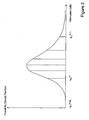
- quantities called ⁇ delimit equal area slices (or areas defined by a given policy) in the probability density function of the average interference power received by the b -th Node B on the m -th PRB.
- the i -th Node B selects for each PRB the UEs having the quantity ⁇ km , i - ⁇ kb , i above a given threshold, and considers all of those UEs as belonging to the potential interferers for that PRB (with respect to the b -th Node B).
- the other UEs are considered as less influential in the interference characterization process and so are discarded (or forwarded to a secondary mechanism that takes into account lower-priority issues).
- equations similar to (4') and (4") can be applied as well when grouping rule (10) is used.
- the dependency on the index q is substituted with the dependency on the PRB index m .
- the grouping criteria may also be based on more than one variable.
- the user equipments can be grouped based both on a service type they are using (such as real-time, non-real-time, best effort, etc.) and on one of the variables described above, such as ⁇ km , i - ⁇ kb , i .
- user equipments which operate in a certain time interval with a given service type may be grouped together.
- the interference coordination mechanism among the Node Bs operates only on certain types of service, and differently depending on the service type, it would then be more efficient to exchange through the X2 interface information related to groups of UEs that are using the same service type.
- the i -th Node B sends via the X2 interface to the b -th Node B data concerning the total uplink average interference power on the m -th PRB for each group or only for certain groups.
- the present invention may also be theoretically applied to any wireless communication system; that it is equally applicable to systems that do or do not perform active interference control in the downlink; and that, in case of active downlink interference control, it is independent of the chosen policy for the downlink.
- average attenuations may be computed directly by user equipments and then sent to the serving transceiver station, alternatively to being computed by the same serving transceiver station.
Landscapes
- Mobile Radio Communication Systems (AREA)
Claims (10)
- Procédé de caractérisation de brouillage de liaison montante dans un système de radiocommunication comprenant une pluralité d'équipements d'utilisateur conçus pour communiquer avec des stations émettrices-réceptrices de desserte respectives dans une bande de fréquences qui est divisée en un nombre de blocs de ressources physiques,
le procédé comprenant :- la détermination de quantités indicatives du brouillage subies par une station émettrice-réceptrice brouillée par des équipements d'utilisateur brouilleurs ; et- l'échange entre des stations émettrices-réceptrices d'informations sur la base desdites quantités et concernant le brouillage à partir desdits équipements d'utilisateur brouilleurs ;caractérisé en ce que la détermination comprend :- la mesure, par lesdits équipements d'utilisateur brouilleurs, des puissances et/ou puissances moyennes des signaux transmis par lesdites stations émettrices-réceptrices brouillées dans les blocs de ressources physiques respectifs ; et- la détermination, par lesdits équipements d'utilisateur brouilleurs ou bien lesdites stations émettrices-réceptrices de desserte, des atténuations de signaux se propageant entre lesdites stations émettrices-réceptrices brouillées et lesdits équipements d'utilisateur brouilleurs sur la base desdites puissances mesurées et des puissances de transmission que lesdites stations émettrices-réceptrices brouillées utilisent pour transmettre lesdits signaux ;le procédé comprenant en outre :- la communication desdits équipements d'utilisateur brouilleurs aux stations émettrices-réceptrices de desserte respectives desdites puissances mesurées ou desdites atténuations déterminées et desdites puissances de transmission brouilleuses que lesdits équipements d'utilisateur brouilleurs utilisent pour transmettre ;dans lequel l'échange comprend l'envoi desdites stations émettrices-réceptrices de desserte auxdites stations émettrices-réceptrices brouillées d'informations concernant le brouillage des équipements d'utilisateur brouilleurs desservis par lesdites stations émettrices-réceptrices de desserte et le brouillage avec lesdites stations émettrices-réceptrices brouillées ;
et dans lequel lesdites informations concernant le brouillage provenant desdits équipements d'utilisateur brouilleurs sont basées sur lesdites atténuations et sur lesdites puissances de transmission brouilleuses que lesdits équipements d'utilisateur brouilleurs utilisent pour transmettre. - Procédé selon la revendication 1, comprenant en outre :- le groupage, par lesdites stations émettrices-réceptrices de desserte, des équipements d'utilisateur brouilleurs selon un critère de groupage donné afin de former des groupes desdits équipements d'utilisateur brouilleurs ;
et dans lequel l'échange comprend l'échange d'informations concernant le brouillage à partir desdits groupes. - Procédé selon la revendication 2, dans lequel ledit groupage est réalisé par rapport à une station émettrice-réceptrice brouillée donnée.
- Procédé selon la revendication 3, comprenant en outre :- pour chaque groupe, le calcul, par ladite station émettrice-réceptrice de desserte, d'une puissance de transmission brouilleuse moyenne totale sur la base des puissances de transmission brouilleuses que lesdits équipements d'utilisateur brouilleurs appartenant au groupe utilisent pour transmettre ;- pour chaque groupe, le calcul, par ladite station émettrice-réceptrice de desserte, d'une atténuation moyenne totale sur la base des atténuations rencontrées par les signaux se propageant entre lesdits équipements d'utilisateur brouilleurs appartenant au groupe et ladite station émettrice-réceptrice brouillée donnée ; et- l'envoi de ladite station émettrice-réceptrice de desserte à ladite station émettrice-réceptrice brouillée donnée desdites puissances de transmission brouilleuses moyennes totales et desdites atténuations moyennes totales desdits groupes ou d'une valeur maximale parmi les rapports des puissances de transmission brouilleuses moyennes totales de tous lesdits groupes et des atténuations moyennes totales de tous lesdits groupes.
- Procédé selon la revendication 4, dans lequel ledit critère de groupage dépend d'au moins l'un des éléments suivants :- lesdites atténuations relatives à ladite station émettrice-réceptrice brouillée donnée ;- une différence entre la puissance de transmission brouilleuse et l'atténuation desdits équipements d'utilisateur brouilleurs ; et- un type de service utilisé par lesdits équipements d'utilisateur brouilleurs.
- Procédé selon la revendication 5, dans lequel le groupage est réalisé en fonction de deux ou plus desdits critères de groupage.
- Système de radiocommunication comprenant une pluralité de stations émettrices-réceptrices radio adaptées pour communiquer avec des équipements d'utilisateur ; ledit système étant adapté pour mettre en oeuvre le procédé de caractérisation de brouillage selon l'une quelconque des revendications précédentes.
- Produit de programme informatique chargeable dans une mémoire d'un processeur d'une station émettrice-réceptrice radio dans un système de radiocommunication et comprenant des parties de code logiciel pour mettre en oeuvre, lorsque le produit de programme informatique est exécuté sur le processeur, le procédé de caractérisation de brouillage selon l'une quelconque des revendications 1 à 6.
- Procédé de diminution du brouillage dans un système de radiocommunication, comprenant :- la caractérisation du brouillage selon l'une quelconque des revendications 1 à 6 ; et- la diminution du brouillage, se produisant au niveau de la gestion des ressources radio (RRM).
- Procédé selon la revendication 9, dans lequel la diminution comprend l'échange entre des stations émettrices-réceptrices de demandes de réduction d'une puissance de transmission desdits équipements d'utilisateur brouilleurs.
Priority Applications (1)
| Application Number | Priority Date | Filing Date | Title |
|---|---|---|---|
| EP07827746.4A EP2116092B1 (fr) | 2007-02-09 | 2007-10-03 | Caractérisation d'interférence de co-canal dans un système de communication sans fil |
Applications Claiming Priority (3)
| Application Number | Priority Date | Filing Date | Title |
|---|---|---|---|
| PCT/EP2007/051302 WO2008095543A1 (fr) | 2007-02-09 | 2007-02-09 | Caractérisation d'interférences de co-canal dans un système de communication sans fil |
| PCT/IT2007/000695 WO2008096383A1 (fr) | 2007-02-09 | 2007-10-03 | Caractérisation d'interférence de co-canal dans un système de communication sans fil |
| EP07827746.4A EP2116092B1 (fr) | 2007-02-09 | 2007-10-03 | Caractérisation d'interférence de co-canal dans un système de communication sans fil |
Publications (2)
| Publication Number | Publication Date |
|---|---|
| EP2116092A1 EP2116092A1 (fr) | 2009-11-11 |
| EP2116092B1 true EP2116092B1 (fr) | 2013-12-11 |
Family
ID=41153237
Family Applications (1)
| Application Number | Title | Priority Date | Filing Date |
|---|---|---|---|
| EP07827746.4A Active EP2116092B1 (fr) | 2007-02-09 | 2007-10-03 | Caractérisation d'interférence de co-canal dans un système de communication sans fil |
Country Status (1)
| Country | Link |
|---|---|
| EP (1) | EP2116092B1 (fr) |
-
2007
- 2007-10-03 EP EP07827746.4A patent/EP2116092B1/fr active Active
Also Published As
| Publication number | Publication date |
|---|---|
| EP2116092A1 (fr) | 2009-11-11 |
Similar Documents
| Publication | Publication Date | Title |
|---|---|---|
| US8843170B2 (en) | Characterization of co-channel interference in a wireless communication system, in particular a cellular radio communication system | |
| EP2494808B1 (fr) | Programmation de ressources radio pour coordination de brouillage intra-systemes dans systemes de communication sans fil | |
| EP2082599B1 (fr) | Attribution de sous-bande dans un système de communication sans fil | |
| EP1808990B1 (fr) | Allocation adaptive de sous-porteuses dans un système FDM ou OFDM à cellules multiples | |
| EP2494807B1 (fr) | Coordination d'interference base sur resultat dans des systemes de communication sans fil | |
| CN101641918A (zh) | 用于干扰管理的回程通信 | |
| EP1931089B1 (fr) | Appareil de communication radio et procédé de communication radio | |
| KR20090057112A (ko) | 서브밴드 스케줄링 및 전력 증폭기 백오프 조절 | |
| EP2566079B1 (fr) | Procédé pour la coordination d'au moins une première transmission à partir d'un émetteur-récepteur à point unique vers un récepteur à point unique et au moins une deuxième transmission à partir d'un émetteur-récepteur multipoints ou vers un récepteur multipoints dans un système de communication radio, et station mobile correspondante | |
| EP2116092B1 (fr) | Caractérisation d'interférence de co-canal dans un système de communication sans fil | |
| Yaacoub et al. | Joint uplink scheduling and interference mitigation in multicell LTE networks | |
| Jorguseski et al. | Downlink resource allocation for evolved UTRAN and WiMAX cellular systems | |
| JP7178685B2 (ja) | 無線基地局および無線通信方法 |
Legal Events
| Date | Code | Title | Description |
|---|---|---|---|
| PUAI | Public reference made under article 153(3) epc to a published international application that has entered the european phase |
Free format text: ORIGINAL CODE: 0009012 |
|
| 17P | Request for examination filed |
Effective date: 20090831 |
|
| AK | Designated contracting states |
Kind code of ref document: A1 Designated state(s): AT BE BG CH CY CZ DE DK EE ES FI FR GB GR HU IE IS IT LI LT LU LV MC MT NL PL PT RO SE SI SK TR |
|
| RIC1 | Information provided on ipc code assigned before grant |
Ipc: H04W 28/00 20090101ALI20091009BHEP Ipc: H04W 4/00 20090101AFI20091009BHEP |
|
| DAX | Request for extension of the european patent (deleted) | ||
| 17Q | First examination report despatched |
Effective date: 20111006 |
|
| GRAP | Despatch of communication of intention to grant a patent |
Free format text: ORIGINAL CODE: EPIDOSNIGR1 |
|
| INTG | Intention to grant announced |
Effective date: 20130702 |
|
| GRAS | Grant fee paid |
Free format text: ORIGINAL CODE: EPIDOSNIGR3 |
|
| GRAA | (expected) grant |
Free format text: ORIGINAL CODE: 0009210 |
|
| AK | Designated contracting states |
Kind code of ref document: B1 Designated state(s): AT BE BG CH CY CZ DE DK EE ES FI FR GB GR HU IE IS IT LI LT LU LV MC MT NL PL PT RO SE SI SK TR |
|
| REG | Reference to a national code |
Ref country code: GB Ref legal event code: FG4D |
|
| REG | Reference to a national code |
Ref country code: CH Ref legal event code: EP |
|
| REG | Reference to a national code |
Ref country code: AT Ref legal event code: REF Ref document number: 645110 Country of ref document: AT Kind code of ref document: T Effective date: 20140115 |
|
| REG | Reference to a national code |
Ref country code: IE Ref legal event code: FG4D |
|
| REG | Reference to a national code |
Ref country code: DE Ref legal event code: R096 Ref document number: 602007034240 Country of ref document: DE Effective date: 20140206 |
|
| REG | Reference to a national code |
Ref country code: SE Ref legal event code: TRGR |
|
| REG | Reference to a national code |
Ref country code: NL Ref legal event code: VDEP Effective date: 20131211 |
|
| REG | Reference to a national code |
Ref country code: AT Ref legal event code: MK05 Ref document number: 645110 Country of ref document: AT Kind code of ref document: T Effective date: 20131211 |
|
| PG25 | Lapsed in a contracting state [announced via postgrant information from national office to epo] |
Ref country code: NL Free format text: LAPSE BECAUSE OF FAILURE TO SUBMIT A TRANSLATION OF THE DESCRIPTION OR TO PAY THE FEE WITHIN THE PRESCRIBED TIME-LIMIT Effective date: 20131211 Ref country code: LT Free format text: LAPSE BECAUSE OF FAILURE TO SUBMIT A TRANSLATION OF THE DESCRIPTION OR TO PAY THE FEE WITHIN THE PRESCRIBED TIME-LIMIT Effective date: 20131211 |
|
| REG | Reference to a national code |
Ref country code: LT Ref legal event code: MG4D |
|
| PG25 | Lapsed in a contracting state [announced via postgrant information from national office to epo] |
Ref country code: LV Free format text: LAPSE BECAUSE OF FAILURE TO SUBMIT A TRANSLATION OF THE DESCRIPTION OR TO PAY THE FEE WITHIN THE PRESCRIBED TIME-LIMIT Effective date: 20131211 Ref country code: CY Free format text: LAPSE BECAUSE OF FAILURE TO SUBMIT A TRANSLATION OF THE DESCRIPTION OR TO PAY THE FEE WITHIN THE PRESCRIBED TIME-LIMIT Effective date: 20131211 Ref country code: AT Free format text: LAPSE BECAUSE OF FAILURE TO SUBMIT A TRANSLATION OF THE DESCRIPTION OR TO PAY THE FEE WITHIN THE PRESCRIBED TIME-LIMIT Effective date: 20131211 |
|
| PG25 | Lapsed in a contracting state [announced via postgrant information from national office to epo] |
Ref country code: BE Free format text: LAPSE BECAUSE OF FAILURE TO SUBMIT A TRANSLATION OF THE DESCRIPTION OR TO PAY THE FEE WITHIN THE PRESCRIBED TIME-LIMIT Effective date: 20131211 Ref country code: IS Free format text: LAPSE BECAUSE OF FAILURE TO SUBMIT A TRANSLATION OF THE DESCRIPTION OR TO PAY THE FEE WITHIN THE PRESCRIBED TIME-LIMIT Effective date: 20140411 Ref country code: EE Free format text: LAPSE BECAUSE OF FAILURE TO SUBMIT A TRANSLATION OF THE DESCRIPTION OR TO PAY THE FEE WITHIN THE PRESCRIBED TIME-LIMIT Effective date: 20131211 |
|
| PG25 | Lapsed in a contracting state [announced via postgrant information from national office to epo] |
Ref country code: CZ Free format text: LAPSE BECAUSE OF FAILURE TO SUBMIT A TRANSLATION OF THE DESCRIPTION OR TO PAY THE FEE WITHIN THE PRESCRIBED TIME-LIMIT Effective date: 20131211 Ref country code: PL Free format text: LAPSE BECAUSE OF FAILURE TO SUBMIT A TRANSLATION OF THE DESCRIPTION OR TO PAY THE FEE WITHIN THE PRESCRIBED TIME-LIMIT Effective date: 20131211 Ref country code: RO Free format text: LAPSE BECAUSE OF FAILURE TO SUBMIT A TRANSLATION OF THE DESCRIPTION OR TO PAY THE FEE WITHIN THE PRESCRIBED TIME-LIMIT Effective date: 20131211 Ref country code: SK Free format text: LAPSE BECAUSE OF FAILURE TO SUBMIT A TRANSLATION OF THE DESCRIPTION OR TO PAY THE FEE WITHIN THE PRESCRIBED TIME-LIMIT Effective date: 20131211 Ref country code: PT Free format text: LAPSE BECAUSE OF FAILURE TO SUBMIT A TRANSLATION OF THE DESCRIPTION OR TO PAY THE FEE WITHIN THE PRESCRIBED TIME-LIMIT Effective date: 20140411 Ref country code: ES Free format text: LAPSE BECAUSE OF FAILURE TO SUBMIT A TRANSLATION OF THE DESCRIPTION OR TO PAY THE FEE WITHIN THE PRESCRIBED TIME-LIMIT Effective date: 20131211 |
|
| REG | Reference to a national code |
Ref country code: DE Ref legal event code: R097 Ref document number: 602007034240 Country of ref document: DE |
|
| PLBE | No opposition filed within time limit |
Free format text: ORIGINAL CODE: 0009261 |
|
| STAA | Information on the status of an ep patent application or granted ep patent |
Free format text: STATUS: NO OPPOSITION FILED WITHIN TIME LIMIT |
|
| PG25 | Lapsed in a contracting state [announced via postgrant information from national office to epo] |
Ref country code: DK Free format text: LAPSE BECAUSE OF FAILURE TO SUBMIT A TRANSLATION OF THE DESCRIPTION OR TO PAY THE FEE WITHIN THE PRESCRIBED TIME-LIMIT Effective date: 20131211 |
|
| 26N | No opposition filed |
Effective date: 20140912 |
|
| REG | Reference to a national code |
Ref country code: DE Ref legal event code: R097 Ref document number: 602007034240 Country of ref document: DE Effective date: 20140912 |
|
| PG25 | Lapsed in a contracting state [announced via postgrant information from national office to epo] |
Ref country code: SI Free format text: LAPSE BECAUSE OF FAILURE TO SUBMIT A TRANSLATION OF THE DESCRIPTION OR TO PAY THE FEE WITHIN THE PRESCRIBED TIME-LIMIT Effective date: 20131211 |
|
| PG25 | Lapsed in a contracting state [announced via postgrant information from national office to epo] |
Ref country code: MC Free format text: LAPSE BECAUSE OF FAILURE TO SUBMIT A TRANSLATION OF THE DESCRIPTION OR TO PAY THE FEE WITHIN THE PRESCRIBED TIME-LIMIT Effective date: 20131211 Ref country code: LU Free format text: LAPSE BECAUSE OF FAILURE TO SUBMIT A TRANSLATION OF THE DESCRIPTION OR TO PAY THE FEE WITHIN THE PRESCRIBED TIME-LIMIT Effective date: 20141003 |
|
| REG | Reference to a national code |
Ref country code: CH Ref legal event code: PL |
|
| REG | Reference to a national code |
Ref country code: IE Ref legal event code: MM4A |
|
| PG25 | Lapsed in a contracting state [announced via postgrant information from national office to epo] |
Ref country code: CH Free format text: LAPSE BECAUSE OF NON-PAYMENT OF DUE FEES Effective date: 20141031 Ref country code: LI Free format text: LAPSE BECAUSE OF NON-PAYMENT OF DUE FEES Effective date: 20141031 |
|
| REG | Reference to a national code |
Ref country code: FR Ref legal event code: PLFP Year of fee payment: 9 |
|
| PG25 | Lapsed in a contracting state [announced via postgrant information from national office to epo] |
Ref country code: IE Free format text: LAPSE BECAUSE OF NON-PAYMENT OF DUE FEES Effective date: 20141003 |
|
| PG25 | Lapsed in a contracting state [announced via postgrant information from national office to epo] |
Ref country code: BG Free format text: LAPSE BECAUSE OF FAILURE TO SUBMIT A TRANSLATION OF THE DESCRIPTION OR TO PAY THE FEE WITHIN THE PRESCRIBED TIME-LIMIT Effective date: 20131211 |
|
| PG25 | Lapsed in a contracting state [announced via postgrant information from national office to epo] |
Ref country code: GR Free format text: LAPSE BECAUSE OF FAILURE TO SUBMIT A TRANSLATION OF THE DESCRIPTION OR TO PAY THE FEE WITHIN THE PRESCRIBED TIME-LIMIT Effective date: 20140312 |
|
| PG25 | Lapsed in a contracting state [announced via postgrant information from national office to epo] |
Ref country code: HU Free format text: LAPSE BECAUSE OF FAILURE TO SUBMIT A TRANSLATION OF THE DESCRIPTION OR TO PAY THE FEE WITHIN THE PRESCRIBED TIME-LIMIT; INVALID AB INITIO Effective date: 20071003 Ref country code: TR Free format text: LAPSE BECAUSE OF FAILURE TO SUBMIT A TRANSLATION OF THE DESCRIPTION OR TO PAY THE FEE WITHIN THE PRESCRIBED TIME-LIMIT Effective date: 20131211 Ref country code: MT Free format text: LAPSE BECAUSE OF FAILURE TO SUBMIT A TRANSLATION OF THE DESCRIPTION OR TO PAY THE FEE WITHIN THE PRESCRIBED TIME-LIMIT Effective date: 20131211 |
|
| REG | Reference to a national code |
Ref country code: FR Ref legal event code: PLFP Year of fee payment: 10 |
|
| REG | Reference to a national code |
Ref country code: FR Ref legal event code: PLFP Year of fee payment: 11 |
|
| REG | Reference to a national code |
Ref country code: FR Ref legal event code: PLFP Year of fee payment: 12 |
|
| P01 | Opt-out of the competence of the unified patent court (upc) registered |
Effective date: 20230529 |
|
| P02 | Opt-out of the competence of the unified patent court (upc) changed |
Effective date: 20230604 |
|
| PGFP | Annual fee paid to national office [announced via postgrant information from national office to epo] |
Ref country code: DE Payment date: 20251020 Year of fee payment: 19 |
|
| PGFP | Annual fee paid to national office [announced via postgrant information from national office to epo] |
Ref country code: GB Payment date: 20251029 Year of fee payment: 19 |
|
| PGFP | Annual fee paid to national office [announced via postgrant information from national office to epo] |
Ref country code: IT Payment date: 20251031 Year of fee payment: 19 Ref country code: FI Payment date: 20251022 Year of fee payment: 19 |
|
| PGFP | Annual fee paid to national office [announced via postgrant information from national office to epo] |
Ref country code: FR Payment date: 20251024 Year of fee payment: 19 |
|
| PGFP | Annual fee paid to national office [announced via postgrant information from national office to epo] |
Ref country code: SE Payment date: 20251023 Year of fee payment: 19 |