EP2116153A1 - Procédé de fabrication d'un article support, article support et dispositif support l'incluant - Google Patents
Procédé de fabrication d'un article support, article support et dispositif support l'incluant Download PDFInfo
- Publication number
- EP2116153A1 EP2116153A1 EP09159810A EP09159810A EP2116153A1 EP 2116153 A1 EP2116153 A1 EP 2116153A1 EP 09159810 A EP09159810 A EP 09159810A EP 09159810 A EP09159810 A EP 09159810A EP 2116153 A1 EP2116153 A1 EP 2116153A1
- Authority
- EP
- European Patent Office
- Prior art keywords
- support
- article
- patient
- chair
- array
- Prior art date
- Legal status (The legal status is an assumption and is not a legal conclusion. Google has not performed a legal analysis and makes no representation as to the accuracy of the status listed.)
- Withdrawn
Links
- 238000000034 method Methods 0.000 title claims abstract description 24
- 238000004519 manufacturing process Methods 0.000 claims abstract description 9
- 230000007246 mechanism Effects 0.000 claims description 8
- 238000003801 milling Methods 0.000 claims description 7
- 208000008035 Back Pain Diseases 0.000 claims description 6
- 239000000463 material Substances 0.000 claims description 6
- 208000002193 Pain Diseases 0.000 claims description 5
- 239000004794 expanded polystyrene Substances 0.000 claims description 5
- 239000011347 resin Substances 0.000 claims description 4
- 229920005989 resin Polymers 0.000 claims description 4
- 238000000576 coating method Methods 0.000 claims description 2
- 239000011248 coating agent Substances 0.000 claims 1
- OSGAYBCDTDRGGQ-UHFFFAOYSA-L calcium sulfate Inorganic materials [Ca+2].[O-]S([O-])(=O)=O OSGAYBCDTDRGGQ-UHFFFAOYSA-L 0.000 description 2
- ZOMBKNNSYQHRCA-UHFFFAOYSA-J calcium sulfate hemihydrate Chemical compound O.[Ca+2].[Ca+2].[O-]S([O-])(=O)=O.[O-]S([O-])(=O)=O ZOMBKNNSYQHRCA-UHFFFAOYSA-J 0.000 description 2
- 238000011960 computer-aided design Methods 0.000 description 2
- 230000006378 damage Effects 0.000 description 2
- 230000000694 effects Effects 0.000 description 2
- 230000003203 everyday effect Effects 0.000 description 2
- 239000012530 fluid Substances 0.000 description 2
- 239000011507 gypsum plaster Substances 0.000 description 2
- 230000008569 process Effects 0.000 description 2
- OKTJSMMVPCPJKN-UHFFFAOYSA-N Carbon Chemical compound [C] OKTJSMMVPCPJKN-UHFFFAOYSA-N 0.000 description 1
- VAYOSLLFUXYJDT-RDTXWAMCSA-N Lysergic acid diethylamide Chemical compound C1=CC(C=2[C@H](N(C)C[C@@H](C=2)C(=O)N(CC)CC)C2)=C3C2=CNC3=C1 VAYOSLLFUXYJDT-RDTXWAMCSA-N 0.000 description 1
- 206010073713 Musculoskeletal injury Diseases 0.000 description 1
- 206010033372 Pain and discomfort Diseases 0.000 description 1
- 229910000831 Steel Inorganic materials 0.000 description 1
- 208000027418 Wounds and injury Diseases 0.000 description 1
- 230000009471 action Effects 0.000 description 1
- 239000000853 adhesive Substances 0.000 description 1
- 230000001070 adhesive effect Effects 0.000 description 1
- 230000003466 anti-cipated effect Effects 0.000 description 1
- 230000008901 benefit Effects 0.000 description 1
- 229910052799 carbon Inorganic materials 0.000 description 1
- 238000005266 casting Methods 0.000 description 1
- 239000002131 composite material Substances 0.000 description 1
- 239000012141 concentrate Substances 0.000 description 1
- 239000000835 fiber Substances 0.000 description 1
- 239000003365 glass fiber Substances 0.000 description 1
- 230000005484 gravity Effects 0.000 description 1
- 208000014674 injury Diseases 0.000 description 1
- 210000004705 lumbosacral region Anatomy 0.000 description 1
- 239000002184 metal Substances 0.000 description 1
- 239000004033 plastic Substances 0.000 description 1
- 229920003023 plastic Polymers 0.000 description 1
- 230000002035 prolonged effect Effects 0.000 description 1
- 239000010959 steel Substances 0.000 description 1
- 238000009423 ventilation Methods 0.000 description 1
- 239000002023 wood Substances 0.000 description 1
Images




Classifications
-
- A—HUMAN NECESSITIES
- A47—FURNITURE; DOMESTIC ARTICLES OR APPLIANCES; COFFEE MILLS; SPICE MILLS; SUCTION CLEANERS IN GENERAL
- A47C—CHAIRS; SOFAS; BEDS
- A47C31/00—Details or accessories for chairs, beds, or the like, not provided for in other groups of this subclass, e.g. upholstery fasteners, mattress protectors, stretching devices for mattress nets
- A47C31/12—Means, e.g. measuring means, for adapting chairs, beds or mattresses to the shape or weight of persons
- A47C31/126—Means, e.g. measuring means, for adapting chairs, beds or mattresses to the shape or weight of persons for chairs
Definitions
- the present invention relates to a method of producing a support article, a support article and a support device incorporating the same. More particularly, the present invention relates to a method of producing a support article for a part of the body, in particular the back, a support article for the body and a body support device incorporating the article.
- Chronic back pain can be a highly painful ailment that restricts a sufferer's movement and prevents the sufferer from enjoying the everyday things in life that others take for granted, such as enjoying a good night's sleep, being mobile and being able to concentrate on work or leisure activities. Any way of alleviating the sufferer's pain is highly desirable.
- plaster of paris It is known to take castings of individual parts of the human body using, for example, plaster of paris.
- such an approach suffers from various drawbacks when applied to people suffering from back pain or other musculoskeletal injuries.
- the setting reaction generates a considerable amount of heat which may, in itself, be painful.
- the present invention seeks to overcome, or at least mitigate the problems of the prior art.
- one aspect of the present invention provides a method of producing a support article for part of the human body, in particular the back, the method comprising the steps of:
- An advantage of this method is that the support article is tailored to the body part when in its relaxed state, thereby alleviating pain and discomfort.
- a second aspect of the present invention provides a support article produced by the method set out above.
- a third aspect of the present invention provides a support device for alleviating pain in a patient suffering from back pain or a musculoskeletal ailment, the support device comprising a support article having a support surface, the support surface having a shape based on the body part of the patient that is to be supported, and the article being arranged within the device to support the body part when in a reclined or partially reclined state.
- Non-contact 3D digitisers use laser beam light sectioning technology to scan work pieces.
- the light reflected from the work piece is obtained using a digital camera.
- Three-dimensional data is then created by a triangulation process to determine distance information.
- the array of individual points in 3D space can then be joined up to build a three dimensional representation of the surface of the work piece being scanned using appropriate computer software.
- the scanning process is very rapid, taking three seconds or less to scan a substantial area of a work piece.
- Examples of such non-contact 3D digitisers are the VI-91 (known as the VIVID 9i outside Europe), the VI-910 (VIVID 910 outside Europe) and the RANGE7, all produced by Konica-Minolta. These products typically quote an accuracy of +/- less than 100 microns, indeed as low as +/- 40 microns for each measured point.
- the first stage of the present invention is to appropriately position the portion of a patient's body, typically their back with respect to a digitiser of the type described above and to obtain an array of electronically encoded points defined in three dimensions, corresponding to points on the surface of the back.
- a digitiser of the type described above
- no particular fixing or bracing of the patient is needed to prevent movement, and there is no contact between the digitiser and the body.
- multiple scans may be required to obtain a complete set of points for the portion of the body in question, but these can be "stitched together" to form a complete array of points.
- the raw data from the digitiser can then be input into a suitable computer aided design (CAD) software such as Solidworks RTM .
- CAD computer aided design
- the support article properly supports the back in the extended state it will be in when the patient is reclined in the chair, but the general shape of the back can only be effectively scanned when upright and the spine is compressed. Different sections of the back may compress by different amounts when upright. This being so, five zones between the nape of the neck and the lumbar region back are measured, thus allowing factors appropriate to each area of the back to be used when calculating extension. Although a larger or smaller number of zones may be used, using five has been found to produce a suitable level of accuracy.
- Each zone is marked by microdots placed on the surface of the back at predetermined intervals.
- two scans are taken. Firstly, the patient is scanned whilst their spine is upright, allowing the general shape of the back (including the spine, ribs, shoulders etc) to be determined. In the upright position the spine is shortened because fluid exits the joints between vertebrae. The patient then lies on their side for at least around five minutes, allowing the back to settle into shape and the spine to lengthen slightly due to the fluid re-entering the joints, whereupon the second scan is taken whilst the patient remains on their side and the length of the spine found, again split into the same five zones.
- the array of 3D points obtained from the digitiser can be converted by suitably skilled personnel to provide a 3D surface of the patient's back that may be manipulated within the CAD software (in particular to provide a "negative" of the surface) like any other design feature.
- the elongation data for each zone are applied to the corresponding shape data found during the first scan to produce an accurate negative of the shape and length of the back. This negative surface may then be incorporated into a design for a support article that may then be manufactured.
- the support article 10 is a block of expanded polystyrene in this embodiment.
- the support article 10 comprises a rear face 14 shaped to be mounted within a larger support device and a contoured front face 16.
- the front face 16 has a basic shape that is intended to generally reflect the curves of a person's back and therefore provide a good starting point for the finished support article without impeding the movement of the patient unduly when positioned therein.
- the user of the CAD software then superimposes the support surface 12 onto the front face 16 such that the major surfaces of the patient's back are fully represented by the support surface 12 in a 3D model of the article 10.
- this 3D model of the support article 10 may be saved in a suitable format that may be read by a computer aided manufacturing (CAM) device such as a milling or routing machine or rapid prototyping device.
- CAM computer aided manufacturing
- the CAM device then produces the article in a known manner.
- a five axis milling machine would be required to produce both the front and rear faces of the support article 10.
- a three axis milling machine may be sufficient.
- a further step following the milling process is required to produce a suitably durable finished support article 10.
- the article is coated in a resin material to provide a rigid and hard-wearing outer surface. It will, however, be appreciated that other suitable coatings may be provided.
- the support article 10 may be manufactured from various other materials, such as wood, plastics or metal that may be directly milled to form the required support surface.
- a mould may be produced by using a milling machine, and the support article 10 produced using the mould.
- the support article 10 may be formed from composite material such as glass fibre or carbon fibre that is laid down onto the mould. This can then be allowed to harden or cure to provide the finished support article 10.
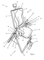
- the support device is a chair 20 comprising a seat subassembly 18 and support subassembly 46.
- the seat subassembly 18 of the chair 20 comprises a conventional seat base 22 and arm rests 24, along with a back rest 26 that incorporates the support article 10.
- the back rest is secured relative to the seat base 22 by a support arm 28 that extends up the rear face (not visible in Figure 2 ) of the back rest.
- the support article 10 itself is secured in a substantially rectangular mounting bracket 30 that extends around its periphery.
- the support article 10 is preferably mounted within the mounting bracket 30 in a removable way, e.g. by using releasable clips or fasteners, but may alternatively be secured to the bracket using adhesive or the bracket secured thereto by the resin that has applied to the expanded polystyrene simultaneously with the application of the resin.
- the support arm 28 extends upwards further to also support a head rest 32.
- the mounting bracket 30 is secured to the support arm 28 by an adjustable mounting arrangement (not shown), such as a plurality of holes in the support arm that provide alternative locations for fitting of a pin or other suitable fastener. This enables the support article to be raised and lowered with respect to the seat base 22. In other embodiments this adjustment may be motorised.
- a front support leg 34 extends forward from the seat base 22 and downwardly to terminate in a base plate 36.
- the base plate prevents the seat from tipping forward when a user sits on it, and furthermore, when a patient stands on the base plate 36 and sits down on the seat base 22, the seat is prevented from tilting backwards.
- a pair of foot rests 38 extend laterally from the support leg, approximately mid-way between the base plate 36 and the seat base 22 and are intended to be used during the reclining of the seat as discussed in more detail below.
- the seat further comprises a cross-member 40 that extends underneath the seat base 22 and which terminates in a pair of vertically extending bars 42 at either end thereof.
- the bars 42 themselves terminate at their upper end with a pair of co-axially extending pivot pins 44 that extend outwardly and are arranged about a common axis X-X.
- the support subassembly 46 is in the form of an A-frame formed from tubular steel members 48 at the front thereof, and 50 at the rear. Both the front and rear tubular members 48 and 50 are substantially 'U' shaped and the rear member additionally comprises a cross bar 52 to provide additional strength.
- the members 48 and 50 are pivotably secured together at point 52 at either side of the seat (only one pivot point visible in Figure 2 ). The angle between the members is maintained by tie rods 55 (only one visible in Figure 2 ) that extend between the Members 48 and 50 on either side of the chair 20 and that may be adjusted to alter the height of the subassembly 46.
- the front tubular member 48 additionally comprises a first and second upwardly directed pivot jaws 54 either side of the chair, and proximate to the pivot point 52.
- the jaws 54 are dimensioned to receive the pivot pins 44 such that the seat subassembly as a whole may pivot with respect to the support subassembly 46 about axis X-X.
- the pivot pins 44 are held in the jaws 54 under the influence of gravity alone.
- suitable catches may be provided to inhibit the removal of the seat subassembly 18.
- the rear tubular member 48 additionally includes handle extensions 56 to the generally upwardly directed portions thereof, that may be used by the patient to assist with the tilting of the seat sub-assembly 18.
- Figure 3 illustrates the rest position of the chair 20.
- the positions of the back rest 26 may first be adjusted as illustrated by the arrow Y, and the support leg may be extended forwards or retracted backwards as illustrated by the arrow Z.
- the user then seats themselves on the seat sub-assembly 18 in the usual manner such that their back fits snugly within the support surface 12.
- the patient's spine still has to support a considerable portion of the patent's weight.
- the patient may themselves recline the entire seat sub-assembly 18 with respect to the support sub-assembly 46. This may be achieved by the patient grasping handles 56, and gently pushing against them to allow the pivoting about axis X-X to occur as indicated by arrow W.
- the geometry of the seat sub-assembly in particular the positioning of the pivot pins 44 with respect to the back rest 26 and seat base 22 results in the chair being inherently stable to allow pivoting without an undue force being required.
- the dimensioning of the support sub-assembly 46 by comparison with the seat sub-assembly 18 means that in whatever position, either upright or reclined, the chair 20 remains stable. Whilst in Figure 4 the seat sub-assembly 18 is shown in a partially reclined position, it will be appreciated that additional reclining may be possible to the point at which the back rest 26 is substantially horizontal (fully reclined).
- the chair 20 is preferably provided with a latching mechanism (not shown) to hold the seat sub-assembly 18 in this position.
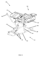
- Figures 5 and 6 show an alternative embodiment of the chair. This embodiment is largely similar to the previous embodiment except for the frame and arm supports. Features which are substantially the same as those of the previous embodiment are given corresponding reference numbers with the additional prefix "1".
- the second embodiment of the chair 120 has a different support subassembly 146.
- the support subassembly 146 is in this embodiment in the form of two inverted T-shaped frames 158, where the horizontal bars 160 of each T are joined by two cross bars 164 at the front of the base and one 166 at the rear.
- the seat subassembly 118 is supported by the upright shaft 162 of each inverted T 158.
- a linear actuator 168 mounted between the two front crossbars and the seat base operates the reclining mechanism of the chair 120.
- the linear actuator 168 comprises a DC motor with a worm gear which acts on a spindle drive system or a ball screw system.
- a pressure sensitive strip may be attached to the underside of the chair (e.g. at the rear of the lower leg support and/or at the rear of the back support).
- the strip is linked to a control system of the linear actuator. If pressure is exerted on the strip, for example if it is brought into contact with an object whilst the chair is being reclined or brought upright, the strip will prevent the linear actuator from further movement. This safety mechanism prevents damage to the obstruction as well as protecting the chair.
- a further embodiment may have handle extensions 56, 156 attached to the seat base 22 rather than to the support subassembly 46, 146.
- the support articles 10 and 110 may be incorporated into other devices such as wheelchairs, car seats or beds.
- the support article may be manufactured to support other parts of the body such as the neck or legs.
- the CAD software may be used to apply certain further adjustments to the profile before the manufacturing of the support article in order to provide corrective support to the patient's back that may assist the recuperation of the patient rather than simply alleviating their pain in the short term.
- the chairs 20 and 120 may take numerous alternative forms and may be adjusted by using numerous alternative mechanisms.
- the reclining motion may be motorised using various actuation mechanisms such as an electric motor driven screw meshing with a sector gear, a wire and pulley arrangement, scissor actuator, linear actuator, or the like.
- actuation mechanisms such as an electric motor driven screw meshing with a sector gear, a wire and pulley arrangement, scissor actuator, linear actuator, or the like.
- a mechanism may be used to aid the patient in standing up from the chair, by lifting the chair into a more forward tilting position.
- the back rest of the chair may recline independently of the seat base
- a thin layer of cushioning material may be provided over the support surface.
- the order in which the two scans are taken may be reversed. If this were the case, the shape data obtained from the second scan could be used to adjust the length data found in the first scan. Once a sufficient body of data has been acquired for multiple patients it may be possible to compile a database or table of adjustment factors that can be applied to the first scan rather than performing a second scan. In order for accurate adjustments to be made enough data should be gathered from a range of people of varying age, race and sex since these factors have been found to affect the extent of elongation.
Landscapes
- Orthopedics, Nursing, And Contraception (AREA)
Applications Claiming Priority (1)
| Application Number | Priority Date | Filing Date | Title |
|---|---|---|---|
| GBGB0808365.1A GB0808365D0 (en) | 2008-05-08 | 2008-05-08 | A method of producing a support article, a support article and a support deviceincorporating the same |
Publications (1)
| Publication Number | Publication Date |
|---|---|
| EP2116153A1 true EP2116153A1 (fr) | 2009-11-11 |
Family
ID=39570997
Family Applications (1)
| Application Number | Title | Priority Date | Filing Date |
|---|---|---|---|
| EP09159810A Withdrawn EP2116153A1 (fr) | 2008-05-08 | 2009-05-08 | Procédé de fabrication d'un article support, article support et dispositif support l'incluant |
Country Status (3)
| Country | Link |
|---|---|
| US (1) | US20090306714A1 (fr) |
| EP (1) | EP2116153A1 (fr) |
| GB (1) | GB0808365D0 (fr) |
Cited By (5)
| Publication number | Priority date | Publication date | Assignee | Title |
|---|---|---|---|---|
| NL2002945C2 (nl) * | 2009-05-29 | 2010-11-30 | Perteon Seats B V | Werkwijze voor het vervaardigen van een zitorthese uit een representatie van het contactvlak van de zitorthese en een op een dergelijke wijze vervaardigde zitorthese. |
| GB2508046A (en) * | 2012-11-16 | 2014-05-21 | Roma Medical Aids Ltd | A measurement jig for designing a bespoke wheelchair |
| WO2014146157A1 (fr) | 2013-03-18 | 2014-09-25 | Rudolf Stonawski | Procédé et dispositif de fabrication d'un dispositif de soutien |
| EP3047760B1 (fr) | 2015-01-21 | 2019-01-09 | Sven Oliver Maier | Procede de fabrication d'un element de support corporel |
| WO2023053027A1 (fr) * | 2021-09-28 | 2023-04-06 | Stander Barend Jacobus | Agencement et système de siège réglable/personnalisé |
Families Citing this family (2)
| Publication number | Priority date | Publication date | Assignee | Title |
|---|---|---|---|---|
| US11564848B2 (en) | 2018-09-27 | 2023-01-31 | Exosseus Llc | Method of producing a custom-fit orthopedic immobilization device |
| US12514711B2 (en) | 2018-09-27 | 2026-01-06 | Exosseus Llc | Method of producing a custom-fit orthopedic immobilization device |
Citations (5)
| Publication number | Priority date | Publication date | Assignee | Title |
|---|---|---|---|---|
| US4890235A (en) * | 1988-07-14 | 1989-12-26 | The Cleveland Clinic Foundation | Computer aided prescription of specialized seats for wheelchairs or other body supports |
| US4972351A (en) * | 1988-07-14 | 1990-11-20 | The Cleveland Clinic Foundation | Computer aided fabrication of wheelchair seats or other body supports |
| WO1991011142A1 (fr) * | 1990-01-26 | 1991-08-08 | University College London | Procede de façonnage de coussins |
| US6141889A (en) * | 1995-07-07 | 2000-11-07 | Baum; Ira M. | Foot support and method (CIP version) |
| US6941188B1 (en) * | 2004-04-26 | 2005-09-06 | Creative Seating Innovations, Inc. | Method of shaping a foam article |
Family Cites Families (19)
| Publication number | Priority date | Publication date | Assignee | Title |
|---|---|---|---|---|
| DE3470710D1 (en) * | 1984-02-13 | 1988-06-01 | Akta Barnsaekerhet Ab | A reversible child restraint for automobiles |
| US5163333A (en) * | 1990-11-28 | 1992-11-17 | The Center For Innovative Technology By Mesne Assignment From The University Of Virginia | Back and trunk positioning and shape sensing apparatus |
| US5328245A (en) * | 1992-10-30 | 1994-07-12 | Thomas J. Marks | Chair having adjustable back support |
| US5297021A (en) * | 1992-11-16 | 1994-03-22 | Koerlin James M | Zero shear recliner/tilt wheelchair seat |
| US5642302A (en) * | 1995-02-21 | 1997-06-24 | Banque De Developpement Du Canada | Method and apparatus for positioning a human body |
| US6125338A (en) * | 1998-04-22 | 2000-09-26 | University Of Pittsburgh | Contour replicating and measuring device |
| US6937348B2 (en) * | 2000-01-28 | 2005-08-30 | Genex Technologies, Inc. | Method and apparatus for generating structural pattern illumination |
| US6549819B1 (en) * | 2000-06-13 | 2003-04-15 | Larry Dale Danduran | Method of producing a three-dimensional image |
| US6597965B2 (en) * | 2001-05-11 | 2003-07-22 | Prosthetics Research Specialists, Inc. | Method for making a prosthetic component cosmetic cover |
| US6733710B2 (en) * | 2002-07-16 | 2004-05-11 | Bald Spot Racing, Llc | Vehicle passenger restraint and method of producing same |
| US20040263863A1 (en) * | 2003-01-27 | 2004-12-30 | Rogers William E | System and method for design and manufacture of custom face masks |
| EP1590172A4 (fr) * | 2003-02-04 | 2006-03-29 | Nova Chem Inc | Composition de revetement pour particules de resine thermoplastique en vue de la formation de conteneur de mousse |
| US7340316B2 (en) * | 2004-06-28 | 2008-03-04 | Hanger Orthopedic Group, Inc. | System and method for producing medical devices |
| US20060227336A1 (en) * | 2005-04-06 | 2006-10-12 | Dinner Todd M | Apparatus and methods for preparing customized personal supports |
| US20080116619A1 (en) * | 2006-11-22 | 2008-05-22 | Wah Kan Cheung | Profile bodyboard |
| US20070200417A1 (en) * | 2005-11-19 | 2007-08-30 | York Julie L | Seat cushion using vertically lapped fiber |
| CN101466291B (zh) * | 2006-04-04 | 2012-11-28 | 罗伯特·B·查飞 | 监测和控制充气设备中压力的方法和装置 |
| US7918510B2 (en) * | 2006-08-08 | 2011-04-05 | Van Den Nieuwboer Johanna Hendrika | Pathology related individual modular orthopedic seating system |
| US9737417B2 (en) * | 2007-07-27 | 2017-08-22 | Vorum Research Corporation | Method, apparatus, media and signals for producing a representation of a mold |
-
2008
- 2008-05-08 GB GBGB0808365.1A patent/GB0808365D0/en not_active Ceased
-
2009
- 2009-05-08 EP EP09159810A patent/EP2116153A1/fr not_active Withdrawn
- 2009-05-08 US US12/437,877 patent/US20090306714A1/en not_active Abandoned
Patent Citations (5)
| Publication number | Priority date | Publication date | Assignee | Title |
|---|---|---|---|---|
| US4890235A (en) * | 1988-07-14 | 1989-12-26 | The Cleveland Clinic Foundation | Computer aided prescription of specialized seats for wheelchairs or other body supports |
| US4972351A (en) * | 1988-07-14 | 1990-11-20 | The Cleveland Clinic Foundation | Computer aided fabrication of wheelchair seats or other body supports |
| WO1991011142A1 (fr) * | 1990-01-26 | 1991-08-08 | University College London | Procede de façonnage de coussins |
| US6141889A (en) * | 1995-07-07 | 2000-11-07 | Baum; Ira M. | Foot support and method (CIP version) |
| US6941188B1 (en) * | 2004-04-26 | 2005-09-06 | Creative Seating Innovations, Inc. | Method of shaping a foam article |
Cited By (12)
| Publication number | Priority date | Publication date | Assignee | Title |
|---|---|---|---|---|
| NL2002945C2 (nl) * | 2009-05-29 | 2010-11-30 | Perteon Seats B V | Werkwijze voor het vervaardigen van een zitorthese uit een representatie van het contactvlak van de zitorthese en een op een dergelijke wijze vervaardigde zitorthese. |
| WO2010137978A3 (fr) * | 2009-05-29 | 2011-01-13 | Perteon Seats B.V. | Procédé de fabrication d'une orthèse d'assise à partir d'une représentation de la surface de contact de l'orthèse d'assise, et orthèse d'assise fabriquée de cette façon |
| US8881356B2 (en) | 2009-05-29 | 2014-11-11 | Perteon Seats B.V. | Method for manufacturing a sitting orthosis from a representation of the contact surface of the sitting orthosis, and a sitting orthosis manufactured in such a manner |
| GB2508046A (en) * | 2012-11-16 | 2014-05-21 | Roma Medical Aids Ltd | A measurement jig for designing a bespoke wheelchair |
| WO2014076457A1 (fr) * | 2012-11-16 | 2014-05-22 | Roma Medical Aids Limited | Gabarit |
| AU2013346563B2 (en) * | 2012-11-16 | 2018-01-18 | Roma Medical Aids Limited | Measuring jig |
| GB2508046B (en) * | 2012-11-16 | 2020-01-22 | Roma Medical Aids Ltd | Measurement jig |
| US11166861B2 (en) | 2012-11-16 | 2021-11-09 | Roma Medical Aids Limited | Method of specifying a customized wheelchair using a measurement jig and computer-implemented model generation device |
| WO2014146157A1 (fr) | 2013-03-18 | 2014-09-25 | Rudolf Stonawski | Procédé et dispositif de fabrication d'un dispositif de soutien |
| AT514093A1 (de) * | 2013-03-18 | 2014-10-15 | Rudolf Stonawski | Verfahren und Vorrichtung zum Herstellen einer Stützvorrichtung |
| EP3047760B1 (fr) | 2015-01-21 | 2019-01-09 | Sven Oliver Maier | Procede de fabrication d'un element de support corporel |
| WO2023053027A1 (fr) * | 2021-09-28 | 2023-04-06 | Stander Barend Jacobus | Agencement et système de siège réglable/personnalisé |
Also Published As
| Publication number | Publication date |
|---|---|
| US20090306714A1 (en) | 2009-12-10 |
| GB0808365D0 (en) | 2008-06-18 |
Similar Documents
| Publication | Publication Date | Title |
|---|---|---|
| EP2116153A1 (fr) | Procédé de fabrication d'un article support, article support et dispositif support l'incluant | |
| CA2743455C (fr) | Siege pivotant | |
| US20240423369A1 (en) | Chair mechanism for an item of furniture for sitting and reclining | |
| US8740303B2 (en) | Customizable chair with multipoint adjustment | |
| US7654974B2 (en) | Recliner spinal traction device | |
| CN1856264A (zh) | 可调高度的工作椅 | |
| CN210471586U (zh) | 一种用于座位单元的调节装置及座位单元 | |
| US7419176B2 (en) | Stand-up wheelchair | |
| JP2013526956A (ja) | 姿勢装置 | |
| WO2009107909A1 (fr) | Fauteuil pour personne handicapée | |
| CN110114042B (zh) | 颈椎牵引装置 | |
| JP3740072B2 (ja) | 連動式リクライニング機構を備えた椅子 | |
| Jang et al. | A study of pressure distribution effect and user satisfaction of a customized off-loading cushion based on 3d modeling: a comparison with conventional air cushions | |
| RU2497427C1 (ru) | Ортопедический стул | |
| TWM353738U (en) | Apparatus for adjusting body posture | |
| CN222870729U (zh) | 健康管理装置 | |
| BE1024555B1 (nl) | Werkwijze en element voor het bepalen van de vorm voor een op maat gemaakte zitschaal | |
| CN222623160U (zh) | 一种可变角度颈椎牵引椅 | |
| CN206355273U (zh) | 甲状腺手术治疗床 | |
| Presperin | Seating systems: The therapist and rehabilitation engineering team | |
| Krasilovsky | Seating assessment and management in a nursing home population | |
| Chen et al. | The design and research of detachable bed and wheelchair based on ergonomics | |
| CN204091448U (zh) | 可多向活动调整腿部型态的摆位椅 | |
| CN217610146U (zh) | 一种符合人体工程学的多功能座椅 | |
| CN219578569U (zh) | 一种老年座椅的可调节装置 |
Legal Events
| Date | Code | Title | Description |
|---|---|---|---|
| PUAI | Public reference made under article 153(3) epc to a published international application that has entered the european phase |
Free format text: ORIGINAL CODE: 0009012 |
|
| AK | Designated contracting states |
Kind code of ref document: A1 Designated state(s): AT BE BG CH CY CZ DE DK EE ES FI FR GB GR HR HU IE IS IT LI LT LU LV MC MK MT NL NO PL PT RO SE SI SK TR |
|
| 17P | Request for examination filed |
Effective date: 20100430 |
|
| 17Q | First examination report despatched |
Effective date: 20100609 |
|
| GRAJ | Information related to disapproval of communication of intention to grant by the applicant or resumption of examination proceedings by the epo deleted |
Free format text: ORIGINAL CODE: EPIDOSDIGR1 |
|
| GRAP | Despatch of communication of intention to grant a patent |
Free format text: ORIGINAL CODE: EPIDOSNIGR1 |
|
| GRAP | Despatch of communication of intention to grant a patent |
Free format text: ORIGINAL CODE: EPIDOSNIGR1 |
|
| STAA | Information on the status of an ep patent application or granted ep patent |
Free format text: STATUS: THE APPLICATION IS DEEMED TO BE WITHDRAWN |
|
| 18D | Application deemed to be withdrawn |
Effective date: 20120208 |