EP2116155A1 - Aufblasbare Kopfstütze mit mehreren Funktionalitäten - Google Patents
Aufblasbare Kopfstütze mit mehreren Funktionalitäten Download PDFInfo
- Publication number
- EP2116155A1 EP2116155A1 EP09158155A EP09158155A EP2116155A1 EP 2116155 A1 EP2116155 A1 EP 2116155A1 EP 09158155 A EP09158155 A EP 09158155A EP 09158155 A EP09158155 A EP 09158155A EP 2116155 A1 EP2116155 A1 EP 2116155A1
- Authority
- EP
- European Patent Office
- Prior art keywords
- compartments
- central
- welding
- cells
- lateral
- Prior art date
- Legal status (The legal status is an assumption and is not a legal conclusion. Google has not performed a legal analysis and makes no representation as to the accuracy of the status listed.)
- Withdrawn
Links
Images


Classifications
-
- A—HUMAN NECESSITIES
- A47—FURNITURE; DOMESTIC ARTICLES OR APPLIANCES; COFFEE MILLS; SPICE MILLS; SUCTION CLEANERS IN GENERAL
- A47G—HOUSEHOLD OR TABLE EQUIPMENT
- A47G9/00—Bed-covers; Counterpanes; Travelling rugs; Sleeping rugs; Sleeping bags; Pillows
- A47G9/10—Pillows
- A47G9/1027—Details of inflatable pillows
Definitions
- the present invention relates to an inflatable head support device, pillow type. More particularly, the present invention relates to a head support device consisting of cells able to be inflated with air.
- the present invention therefore relates to the technical field of support devices of the mattress or cushion type, for supporting the body of a person or part of the body of a person lying down.
- Therapeutic mattresses consisting of inflated air cells, in particular coil-shaped cells extending transversely with respect to the longitudinal direction of the bed on which the mattress is intended to be applied, said cells being fed with air by means of an air pressure regulating system making it possible, as appropriate, to differentiate the air pressure inside the cells in different zones of the mattress according to the parts of the body resting on said areas of the mattress so as to homogenize the interface pressure on the different parts of the body.
- These mattresses in particular make it possible, depending on the number of inflatable elements used, to individually control the pressure and thus the filling of the inflatable elements in the different zones of the mattress to provide a distribution of the interface pressure adapted to the level of each of the body parts of a patient, thanks to a device for regulating the inflation / deflation of the cells.
- an airbag having different cells arranged side by side longitudinally with lateral cells of greater height, so as to create a wedging of the head in a gutter.
- the object of the present invention is to provide a complementary device of the pillow type to fight against pressure ulcers, on the one hand, but also, on the other hand, to facilitate the movements of the head and neck required for the interventions of the nursing staff for the care, more particularly at the level of the head but also in other parts of the body.
- the succession of cells of increasing height of the central compartments creates an inclined plane and a comfortable progressive elevation of the head.
- the cells of the small branch of the L side compartments can support the neck, filling the gap between the two points of contact: occiput and shoulder height.
- This arrangement allows the device in the inflated state to better support the head relative to the neck by avoiding the tilting of the skull backwards below the neck and thus relieve the vertebrae of the neck and promote good blood supply to the head.
- the greater number of said cells of the central compartments added to the small branches of the lateral compartments is to make contact of the skull on the reduced surfaces delimited in the two axial directions XX 'and perpendicular direction YY' in larger numbers, which increases the patient's comfort at the risk of pressure ulcers.
- This configuration according to the invention also has the advantage of being able to adopt a good positioning of the head in different positions.
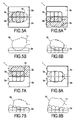
- the head is supported at the neck or neck by the two small branches of the two Ls of the lateral compartments and the skull tilts backwards, the chin and throat being, on the contrary, tipped up.
- This position facilitates the intubation procedure in the trachea of a patient lying on a mattress when the device is used in a hospital or on a therapeutic mattress or bed.
- This configuration of the head support device with the deflated central compartments is also useful for washing the head and hair of a patient or performing care, by inserting a tray in the deflated central area below the patient's skull.
- This laterally pivoted head position is advantageous for performing care in the oral sphere with heavy equipment which must be approached at the maximum of the mouth and, if necessary in part resting on the bed, such as intubation equipment, nasal probe or gastric tube.
- This laterally pivoted head position is also advantageous when it is necessary to pivot the patient's entire body for intervention at the occipital or back level, for example and, generally, to avoid excessive pressure on the patient. skin of the patient that can generate pressure ulcers or treat said pressure sores at the occipital level or on the posterior surface of the patient, in particular at the level of the sacrum or the heel.
- the device according to the invention thus makes it possible to prevent or fight against pressure ulcers in a supplementary way compared to a simple therapeutic mattress of the prior art, as described above.
- An inflatable air device has advantages over pillows of textile or synthetic foam, generally used in hospital beds. Firstly, the device according to the present invention has a greater lightness and reduced size when stored in the deflated state. On the other hand, it is possible to produce such devices from a simple envelope of plastic or impermeable material, which results in the manufacturing cost is significantly reduced compared to pillows filled with textile material or synthetic foam. Last but not least, the costs of use are significantly reduced because it is possible to wash the device between two uses and, therefore, to reuse for different patients unlike foam pillows in particular.
- said central compartments comprise means for limiting their expansion in width.
- width means the dimension in the perpendicular direction YY 'to said direction of the central axis XX'.
- This means of limiting the width may consist, in particular of external connecting means between the central compartments between them on the one hand and between each central compartment and said large branch of the lateral compartment which is adjacent to it or by means of internal connections to the central compartments, such as spacers including a strip of fabric, bringing together the opposite faces of each said central compartment in said direction YY ', perpendicular to the direction of the central axis XX'.
- said central compartments are, on the one hand, interconnected and, on the other hand, connected to said lateral compartments, along their adjacent sides, extending into said direction of the central axis XX ', preferably connected by welding.
- the different cells of said central compartments have an increasing height with a smaller height cell h1 is higher than the lateral compartments of uniform height h.
- said cells of the central compartments are defined by adhesive lines or welding of the upper and lower faces of the compartment between them, said bonding or preferably welding lines extending in a perpendicular direction YY 'to the longitudinal direction XX' said central compartments, the upper and lower faces of each of said cells having in section, in a vertical plane parallel to the central axis of symmetry XX ', a convex rounded profile delimited by said welding lines.
- the term "height” here refers to the dimension in the vertical direction when said device rests on a central axis of symmetry XX 'arranged horizontally.
- said cells of the central compartment communicate with each other pneumatically.
- two adjacent cells at said separation lines communicate with each other within said compartment beyond said separation lines, preferably by welding, delimiting two adjacent cells.
- said lines or separation preferably by welding do not extend over the entire width in the perpendicular direction YY 'to said longitudinal direction of the central compartments.
- each said central compartment comprises four cells of the same width L 2 in the central axial direction XX 'and of the same length I 3 in the direction YY' perpendicular to said central axial direction XX ', but of height h 1 -h 4 gradually increasing from the smaller height cell adjacent to the small branch of the adjacent L-shaped lateral compartment towards the larger cell on the end side of the large branch of the L opposite the small plugged.
- the number of four cells is an optimal compromise between comfort and cost of manufacture.
- the upper faces of the lateral compartments have a convex rounded profile in vertical cross section, perpendicular to the central axis of symmetry XX 'for the large branch of the lateral compartment L-shaped bent and in section in a vertical plane parallel to the central axis of symmetry XX 'for the small branch of the lateral compartment bent in the shape of L.
- the four compartments are made by gluing or preferably welding two thermoplastic sheets against each other, the four compartments being secured at a welding line or peripheral bonding of said support device. and separation lines by welding or gluing separating the different compartments, the device comprising all the different compartments and, where appropriate, the different cells, being made by welding two thermoplastic sheets against each other, glued together or welded at said separation lines by gluing or welding.
- the four compartments are made independently by welding two thermoplastic sheets against each other, each compartment being secured at a peripheral welding line and said central compartments being furthermore secured to each other. preferably at the level of welding or bonding lines separating the different cells, the different compartments being joined to each other by welding or bonding to each other.
- said bonding or welding lines correspond in fact to the ends at the edge of flat gluing or welding areas.
- This bonding or welding in a flat area can, in fact, be achieved by inserting a strip of fabric serving as a spacer between the outer faces of two compartments or two adjacent cells to be glued or soldered.
- said compartments have upper and lower faces having, in the inflated state, convex rounded symmetrical shapes, said L-shaped lateral bent compartments having the shape of an angled bead and said cells of the central compartments. also having a substantially cylindrical coil shape extending along a perpendicular axis YY 'to said central axial direction XX' in the portions bordered by said separation lines by welding or bonding between said cells.
- L and I 1 also mean the lengths of said large and respectively small branches of the L of the lateral compartment, on their external face, it being understood that the lengths on the internal faces, that is to say the faces adjacent to the central compartments are reduced.
- the length of the large branch of the L on its internal face adjacent to the central compartment is equal to the length of the central compartment, as well as the length of the small branch in the direction YY 'of the compartment lateral on its inner face is equal to the width of the central compartments in claim YY '.
- the width I 2 in the direction YY 'perpendicular to the direction of the central axis of symmetry XX' of said lateral compartments at the level of the large branch of the L of said lateral compartments is approximately equal to the width of each of said central compartments in said perpendicular YY direction, and the width L 1 in the central direction XX 'of the small branch of the L of the side compartment, is greater than or equal to the width L 2 in the central direction XX' of each of said plurality of cells.
- central compartments and the convex rounded upper faces of said cells are substantially tangential to the same inclined line D with respect to the horizontal angle ⁇ 5 to 20 °, of preferably 10 to 15 °, said straight extending from the upper side of the adjacent lateral compartment at its small branch of L.
- the angle of 10 ° to 15 ° allows an ideal inclination of the head for the comfort of the patient.
- a head support device is made of films or sheets of PVC or polyurethane or sheets of fabric impregnated with PVC or polyurethane.
- Polyurethane is preferred which, by its flexibility and elasticity, provides a significant improvement in the comfort of the patient.
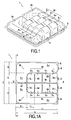
- the head support device comprises two lateral compartments 2a, 2b angled L-shaped symmetrically arranged with respect to an axis central XX 'of the support device so as to form a U or a horseshoe, each lateral compartment comprises a large branch 2a 2 , 2b 2 extending in the longitudinal direction parallel to the axial direction XX' and a small 2a 1 , 2b 1 extending in the direction YY '.
- the two large branches 2a 2 and 2b 2 are parallel to one another, while the two small branches are aligned, the ends of the small limbs 2a 1 of the L of the two L-shaped lateral bent compartments being in contact with each other. on opposite sides of a separating welding line 2c.
- the device is obtained by heat sealing along peripheral welding lines 5 defining the roughly square periphery 5 of the entire device 1 on the one hand, and the separating welding lines 2c, 2d and 3e between the different compartments of on the other hand, as well as 3D separating lines between the individual cells (3 1 a-3 4 a, 3-3 1b 4b) of the two central compartments 3a and 3b.
- the device according to the invention in fact comprises two central compartments 3a and 3b also arranged symmetrically with respect to the longitudinal axis XX 'of the device, the two central compartments being interposed inside the U or being interposed side by side, with their longitudinal sides adjacent along a welding line 3e in the extension of the welding line 2c at the ends of the two small branches 2a 1 and 2b 1 of the side compartments.
- the central compartments are separated from the inner faces of the longitudinal sides of the large branches 2a 2 and 2b 2 , L-shaped side compartments by welding lines 2d.
- the welding lines are bent to form the separation between the small transverse sides 3d 3 of the central compartments extending in the direction YY 'perpendicular to the axial direction XX' and the internal faces of the small branches 2a 1 and 2b 1 of the lateral compartments .
- the small opposite transverse sides 3d 4 of the central compartments on the side of the peripheral welding line 5 arrive at the same level in the direction XX 'as the short sides in the direction YY' at the ends of the large branches 2a 2 and 2b 2 of the compartments lateral bent.
- L and I 1 also mean the lengths of the external faces of said large branches and, respectively, small branches of the L of the lateral compartment, it being understood that the lengths of the internal faces, ie the faces adjacent to the central compartments. are smaller.
- the length of the large branch 2a 2 , 2b 2 of the L on its internal face adjacent to the central compartment is equal to the length L 3 of the central compartment, as well as the length of the inner face of the small branch 2a 1 , 2b 1 in the direction YY 'of the lateral compartment is equal to the width I 3 of the central compartments in the direction YY'.
- the width I 2 in the direction YY 'perpendicular to the direction of the central axis of symmetry XX' of said lateral compartments 2a, 2b at the large branch of the L of said lateral compartments 2a, 2b is approximately equal to the width I 3 of each of said central compartments 3a, 3b in said direction YY 'perpendicular and the width L 1 in the central direction XX' of the small branch of the L of the lateral compartment, is greater than or equal to the width L 2 in the central direction XX 'of each of said cells 3 1 a-3 4 a, 3 1b-3 4b central compartments 3a, 3b and the convex upper faces rounded 3d of said cells are substantially tangent to the same inclined line D with respect to the horizontal angle ⁇ 5 to 20 °, preferably 10 to 15 °, said straight extending from the upper side of the adjacent lateral compartment at its small branch of L.
- Each central compartment 3a, 3b is divided into four cells 3 1 a-3 4 a, 3 1b-3 4b consecutively arranged side by side in said axial direction XX 'of the device, said cells being delimited by separating lines 3c extending in a perpendicular direction YY 'to the longitudinal direction XX' of said central compartments.
- Said cells are delimited by welding lines 3c of the upper and lower faces of the compartment between them, said bonding or welding lines 3c extending in a perpendicular direction YY 'to the longitudinal direction XX' of said central compartments, the upper faces 3d 1 and lower 3d 2 of each of said cells 3 1 a-3 4 a, 3 1 b-3 4 b having in section, in a vertical plane parallel to the central axis of symmetry XX ', a rounded convex profile delimited by said 3c welding lines 1 .
- their height h 15 cm, substantially uniform, is slightly less than the height h4 the smallest cells.
- the term "height” here means the dimension in the vertical direction when said device rests on a central axis of symmetry XX 'arranged horizontally.
- the welding separation lines 3c between the different cells do not extend edge to edge between the two opposite longitudinal sides of the central compartments 3a, 3b, the different cells communicating with each other pneumatically inside said central compartment in the zone at the said separation lines 3c delimiting two adjacent cells.
- Said bent side compartments 2a-2b have upper and lower faces having, in the inflated state, convex rounded symmetrical shapes, said L-shaped lateral bent compartments having the shape of a bent bead and said central compartments 3a, 3b also having a substantially cylindrical coil shape extending along a perpendicular axis YY 'to said central axial direction XX' in the portions bordered by said separation lines by welding or gluing 3c between said cells.
- the upper faces 3d of the lateral compartments 3a, 3b have a convex rounded profile in vertical cross section, perpendicular to the central axis of symmetry XX 'for the large branch of the L-shaped lateral compartment and in section in a parallel vertical plane. to the central axis of symmetry XX 'for the small branch of the L-shaped bent lateral compartment.
- the width (L 1 ) in the central direction (XX') of the small branch of the L of the lateral compartment is greater than or equal to the width (L 2) in the central direction (XX ') of each said cells (3 1 a-3 4 a, 3 1b-3 4b) central compartments (3a, 3b) and convex curved upper surfaces (3d 1 ) said cells are substantially tangential to a same inclined line (D) with respect to the horizontal angle ⁇ of 10 to 15 °, said straight line extending from the upper face of the adjacent lateral compartment at the level of his little branch of L.
- FIG. 4A there is shown the realization of a weld said "flat" along a weld line 3c between a first sheet 3d 1 constituting the upper phases of two adjacent cells and a lower sheet 3d 2 constituting the lower faces of two adjacent cells.
- This flat weld is also performed in the case of separation lines 2c, 2d and 3e between the three compartments, as well as the peripheral welding line 5 of the entire device.
- FIG 4B there is shown a mode of bonding or alternating welding in which is implemented a spacer 3c 1 between the two lateral faces of two cells or two compartments, this type of welding is used for the connection of the different independent compartments as shown on the Figures 2 and 2A .
- each compartment is made from two sheets which are joined to each other along peripheral sealing lines 5 1 , for the side compartments and 5 2 for the central compartments.
- peripheral welding lines 5 1 are flat welding lines, as shown in FIG. Figure 4A .
- the central compartments 3a, 3b they furthermore comprise separation lines 3c between cells which, they are also made in a flat weld as shown in FIG. Figure 4A .
- the welding lines 2c, 2d, 3e of separation between the different compartments are advantageously made using spacers 3c 1 interposed between the faces of the compartments to be welded or glued together.
- the spacer 3c 1 consists of a strip of the same PVC or polyurethane plastic material as that contained in the envelope constituting the different compartments.
- the flanges constituting different cells are joined by flat welding lines 3c.
- the zone of contact between two adjacent cells and the zone of contact between the small side 3d 3 of the cell of smaller height 3 4 a, 3 4 b and a small branch 2b 1 of the lateral compartment is constituted by a flat zone vertical in that the dimensions of the upper faces 3d 1 and 3d 2 of the upper and lower leaves of the constituent envelope are dimensioned to lead to this shape after inflation.
- each of the compartments is sealed and the compartments do not communicate with each other pneumatically, each compartment being provided with a valve connector 6.
- the hatched or dashed areas are the deflated compartments
- the principle of a pillow with air inflatable compartment is advantageous because it allows to regulate if necessary differently the air supply of the different compartments. But in addition, because of the nature of the plastic or waterproof material of the constituent envelopes of the different compartments, the device according to the invention can be washed between two uses and therefore reused by different patients in contrast to the foam head support device because of the risk of contamination within the cellular structure of the foam.
Landscapes
- Health & Medical Sciences (AREA)
- General Health & Medical Sciences (AREA)
- Otolaryngology (AREA)
- Pulmonology (AREA)
- Invalid Beds And Related Equipment (AREA)
Applications Claiming Priority (1)
| Application Number | Priority Date | Filing Date | Title |
|---|---|---|---|
| FR0852995A FR2930880B1 (fr) | 2008-05-06 | 2008-05-06 | Dispositif support de tete gonflable a fonctionnalites multiples |
Publications (1)
| Publication Number | Publication Date |
|---|---|
| EP2116155A1 true EP2116155A1 (de) | 2009-11-11 |
Family
ID=39986449
Family Applications (1)
| Application Number | Title | Priority Date | Filing Date |
|---|---|---|---|
| EP09158155A Withdrawn EP2116155A1 (de) | 2008-05-06 | 2009-04-17 | Aufblasbare Kopfstütze mit mehreren Funktionalitäten |
Country Status (2)
| Country | Link |
|---|---|
| EP (1) | EP2116155A1 (de) |
| FR (1) | FR2930880B1 (de) |
Cited By (4)
| Publication number | Priority date | Publication date | Assignee | Title |
|---|---|---|---|---|
| CN105055092A (zh) * | 2015-08-21 | 2015-11-18 | 无锡市海昌机械设备有限公司 | 一种舒适性优的坐垫 |
| CN108670638A (zh) * | 2018-05-31 | 2018-10-19 | 海宁卫生学校 | 一种病房用床垫 |
| US20230126248A1 (en) * | 2021-10-26 | 2023-04-27 | Michael Kerner | Intubation positioning device |
| US12023185B2 (en) * | 2020-02-11 | 2024-07-02 | Saint Louis University | Positioning system |
Citations (2)
| Publication number | Priority date | Publication date | Assignee | Title |
|---|---|---|---|---|
| WO2006043861A1 (en) | 2004-10-21 | 2006-04-27 | Kjell Svedman | A device for supporting head and neck |
| EP1834546A1 (de) * | 2006-02-27 | 2007-09-19 | UniGreen International A/S | Aufblasbare Tüte |
-
2008
- 2008-05-06 FR FR0852995A patent/FR2930880B1/fr not_active Expired - Fee Related
-
2009
- 2009-04-17 EP EP09158155A patent/EP2116155A1/de not_active Withdrawn
Patent Citations (2)
| Publication number | Priority date | Publication date | Assignee | Title |
|---|---|---|---|---|
| WO2006043861A1 (en) | 2004-10-21 | 2006-04-27 | Kjell Svedman | A device for supporting head and neck |
| EP1834546A1 (de) * | 2006-02-27 | 2007-09-19 | UniGreen International A/S | Aufblasbare Tüte |
Cited By (4)
| Publication number | Priority date | Publication date | Assignee | Title |
|---|---|---|---|---|
| CN105055092A (zh) * | 2015-08-21 | 2015-11-18 | 无锡市海昌机械设备有限公司 | 一种舒适性优的坐垫 |
| CN108670638A (zh) * | 2018-05-31 | 2018-10-19 | 海宁卫生学校 | 一种病房用床垫 |
| US12023185B2 (en) * | 2020-02-11 | 2024-07-02 | Saint Louis University | Positioning system |
| US20230126248A1 (en) * | 2021-10-26 | 2023-04-27 | Michael Kerner | Intubation positioning device |
Also Published As
| Publication number | Publication date |
|---|---|
| FR2930880A1 (fr) | 2009-11-13 |
| FR2930880B1 (fr) | 2012-11-30 |
Similar Documents
| Publication | Publication Date | Title |
|---|---|---|
| EP2005929B1 (de) | Matratze mit heterogener aufblasbarer Struktur | |
| EP0217878B1 (de) | Bettzeug- oder sitzbestandteil | |
| FR2949321A1 (fr) | Dispositif de support comprenant un matelas de dimensions ajustables a l'aide de cellules gonflables | |
| EP2055210A1 (de) | Aufblasbare Zelle, Herstellungsverfahren und Halterungsvorrichtung, die sie umfasst | |
| FR2949320A1 (fr) | Dispositif de basculement lateral | |
| CA2829244C (fr) | Element de literie reversible a quatre cotes | |
| AU2011101697B4 (en) | Tri-Cell Lumbar Support Travel Pillow and Foot Rest | |
| EP0721755A1 (de) | Aufblasbare, teleskopische Zellen für Kissen und Matratzen | |
| EP2116155A1 (de) | Aufblasbare Kopfstütze mit mehreren Funktionalitäten | |
| EP2214537A2 (de) | Zubehör zum abstützen des kopfs in liegender position | |
| FR2470565A1 (fr) | Perfectionnement a un sommier | |
| EP2500004B1 (de) | Aufblasbare Zelle einer Anti-Dekupitusmatratze | |
| EP4225246A1 (de) | Vorrichtung zur lagerung eines menschlichen körperteils | |
| CN113974371A (zh) | 一种电动海绵充气垫 | |
| WO2020178269A1 (fr) | Dispositif de matelas a decompression modulaire, statique ou dynamique | |
| FR2942396A1 (fr) | Dispositif support de tete ou d'avant-bras gonflable | |
| EP2070503B1 (de) | Antidekubitus aufblasbare Matratze | |
| JP5260138B2 (ja) | エアー枕 | |
| EP1707174B1 (de) | Zelle für eine Matratze zur Prävention von Wundliegen | |
| WO2022079377A1 (fr) | Dispositif de soutien d'un corps humain en position allongee | |
| FR2937861A1 (fr) | Cellule gonflable de matelas anti-escarres avec soudure(s) oblongue(s) | |
| FR2542589A1 (fr) | Structures souples comportant plusieurs volumes gonfles a des pressions differentes pour la realisation d'elements de mobilier | |
| FR2700950A1 (fr) | Matelas anti-escarres à gonflement alterné. | |
| FR2778097A1 (fr) | Coussin anti escarres et son procede de fabrication | |
| FR2647000A1 (fr) | Matelas |
Legal Events
| Date | Code | Title | Description |
|---|---|---|---|
| PUAI | Public reference made under article 153(3) epc to a published international application that has entered the european phase |
Free format text: ORIGINAL CODE: 0009012 |
|
| AK | Designated contracting states |
Kind code of ref document: A1 Designated state(s): AT BE BG CH CY CZ DE DK EE ES FI FR GB GR HR HU IE IS IT LI LT LU LV MC MK MT NL NO PL PT RO SE SI SK TR |
|
| 17P | Request for examination filed |
Effective date: 20100309 |
|
| GRAP | Despatch of communication of intention to grant a patent |
Free format text: ORIGINAL CODE: EPIDOSNIGR1 |
|
| RIC1 | Information provided on ipc code assigned before grant |
Ipc: A47G 9/10 20060101AFI20140626BHEP |
|
| INTG | Intention to grant announced |
Effective date: 20140724 |
|
| STAA | Information on the status of an ep patent application or granted ep patent |
Free format text: STATUS: THE APPLICATION IS DEEMED TO BE WITHDRAWN |
|
| 18D | Application deemed to be withdrawn |
Effective date: 20141101 |