EP2116168B1 - Dispositif de séparation d'impuretés doté d'un réglage de niveau - Google Patents
Dispositif de séparation d'impuretés doté d'un réglage de niveau Download PDFInfo
- Publication number
- EP2116168B1 EP2116168B1 EP09006072.4A EP09006072A EP2116168B1 EP 2116168 B1 EP2116168 B1 EP 2116168B1 EP 09006072 A EP09006072 A EP 09006072A EP 2116168 B1 EP2116168 B1 EP 2116168B1
- Authority
- EP
- European Patent Office
- Prior art keywords
- cleaning
- tank
- fluid
- control
- level
- Prior art date
- Legal status (The legal status is an assumption and is not a legal conclusion. Google has not performed a legal analysis and makes no representation as to the accuracy of the status listed.)
- Active
Links
Images

Classifications
-
- A—HUMAN NECESSITIES
- A47—FURNITURE; DOMESTIC ARTICLES OR APPLIANCES; COFFEE MILLS; SPICE MILLS; SUCTION CLEANERS IN GENERAL
- A47L—DOMESTIC WASHING OR CLEANING; SUCTION CLEANERS IN GENERAL
- A47L15/00—Washing or rinsing machines for crockery or tableware
- A47L15/42—Details
- A47L15/4244—Water-level measuring or regulating arrangements
-
- A—HUMAN NECESSITIES
- A47—FURNITURE; DOMESTIC ARTICLES OR APPLIANCES; COFFEE MILLS; SPICE MILLS; SUCTION CLEANERS IN GENERAL
- A47L—DOMESTIC WASHING OR CLEANING; SUCTION CLEANERS IN GENERAL
- A47L15/00—Washing or rinsing machines for crockery or tableware
- A47L15/24—Washing or rinsing machines for crockery or tableware with movement of the crockery baskets by conveyors
- A47L15/241—Washing or rinsing machines for crockery or tableware with movement of the crockery baskets by conveyors the dishes moving in a horizontal plane
-
- A—HUMAN NECESSITIES
- A47—FURNITURE; DOMESTIC ARTICLES OR APPLIANCES; COFFEE MILLS; SPICE MILLS; SUCTION CLEANERS IN GENERAL
- A47L—DOMESTIC WASHING OR CLEANING; SUCTION CLEANERS IN GENERAL
- A47L15/00—Washing or rinsing machines for crockery or tableware
- A47L15/24—Washing or rinsing machines for crockery or tableware with movement of the crockery baskets by conveyors
- A47L15/247—Details specific to conveyor-type machines, e.g. curtains
-
- D—TEXTILES; PAPER
- D06—TREATMENT OF TEXTILES OR THE LIKE; LAUNDERING; FLEXIBLE MATERIALS NOT OTHERWISE PROVIDED FOR
- D06F—LAUNDERING, DRYING, IRONING, PRESSING OR FOLDING TEXTILE ARTICLES
- D06F39/00—Details of washing machines not specific to a single type of machines covered by groups D06F9/00 - D06F27/00
- D06F39/08—Liquid supply or discharge arrangements
- D06F39/087—Water level measuring or regulating devices
-
- A—HUMAN NECESSITIES
- A47—FURNITURE; DOMESTIC ARTICLES OR APPLIANCES; COFFEE MILLS; SPICE MILLS; SUCTION CLEANERS IN GENERAL
- A47L—DOMESTIC WASHING OR CLEANING; SUCTION CLEANERS IN GENERAL
- A47L15/00—Washing or rinsing machines for crockery or tableware
- A47L15/42—Details
- A47L15/4202—Water filter means or strainers
-
- Y—GENERAL TAGGING OF NEW TECHNOLOGICAL DEVELOPMENTS; GENERAL TAGGING OF CROSS-SECTIONAL TECHNOLOGIES SPANNING OVER SEVERAL SECTIONS OF THE IPC; TECHNICAL SUBJECTS COVERED BY FORMER USPC CROSS-REFERENCE ART COLLECTIONS [XRACs] AND DIGESTS
- Y10—TECHNICAL SUBJECTS COVERED BY FORMER USPC
- Y10T—TECHNICAL SUBJECTS COVERED BY FORMER US CLASSIFICATION
- Y10T137/00—Fluid handling
- Y10T137/0318—Processes
- Y10T137/0324—With control of flow by a condition or characteristic of a fluid
-
- Y—GENERAL TAGGING OF NEW TECHNOLOGICAL DEVELOPMENTS; GENERAL TAGGING OF CROSS-SECTIONAL TECHNOLOGIES SPANNING OVER SEVERAL SECTIONS OF THE IPC; TECHNICAL SUBJECTS COVERED BY FORMER USPC CROSS-REFERENCE ART COLLECTIONS [XRACs] AND DIGESTS
- Y10—TECHNICAL SUBJECTS COVERED BY FORMER USPC
- Y10T—TECHNICAL SUBJECTS COVERED BY FORMER US CLASSIFICATION
- Y10T137/00—Fluid handling
- Y10T137/2713—Siphons
- Y10T137/2774—Periodic or accumulation responsive discharge
-
- Y—GENERAL TAGGING OF NEW TECHNOLOGICAL DEVELOPMENTS; GENERAL TAGGING OF CROSS-SECTIONAL TECHNOLOGIES SPANNING OVER SEVERAL SECTIONS OF THE IPC; TECHNICAL SUBJECTS COVERED BY FORMER USPC CROSS-REFERENCE ART COLLECTIONS [XRACs] AND DIGESTS
- Y10—TECHNICAL SUBJECTS COVERED BY FORMER USPC
- Y10T—TECHNICAL SUBJECTS COVERED BY FORMER US CLASSIFICATION
- Y10T137/00—Fluid handling
- Y10T137/4673—Plural tanks or compartments with parallel flow
- Y10T137/479—Flow dividing compartments
-
- Y—GENERAL TAGGING OF NEW TECHNOLOGICAL DEVELOPMENTS; GENERAL TAGGING OF CROSS-SECTIONAL TECHNOLOGIES SPANNING OVER SEVERAL SECTIONS OF THE IPC; TECHNICAL SUBJECTS COVERED BY FORMER USPC CROSS-REFERENCE ART COLLECTIONS [XRACs] AND DIGESTS
- Y10—TECHNICAL SUBJECTS COVERED BY FORMER USPC
- Y10T—TECHNICAL SUBJECTS COVERED BY FORMER US CLASSIFICATION
- Y10T137/00—Fluid handling
- Y10T137/7287—Liquid level responsive or maintaining systems
-
- Y—GENERAL TAGGING OF NEW TECHNOLOGICAL DEVELOPMENTS; GENERAL TAGGING OF CROSS-SECTIONAL TECHNOLOGIES SPANNING OVER SEVERAL SECTIONS OF THE IPC; TECHNICAL SUBJECTS COVERED BY FORMER USPC CROSS-REFERENCE ART COLLECTIONS [XRACs] AND DIGESTS
- Y10—TECHNICAL SUBJECTS COVERED BY FORMER USPC
- Y10T—TECHNICAL SUBJECTS COVERED BY FORMER US CLASSIFICATION
- Y10T137/00—Fluid handling
- Y10T137/7287—Liquid level responsive or maintaining systems
- Y10T137/729—Washing machine cycle control
-
- Y—GENERAL TAGGING OF NEW TECHNOLOGICAL DEVELOPMENTS; GENERAL TAGGING OF CROSS-SECTIONAL TECHNOLOGIES SPANNING OVER SEVERAL SECTIONS OF THE IPC; TECHNICAL SUBJECTS COVERED BY FORMER USPC CROSS-REFERENCE ART COLLECTIONS [XRACs] AND DIGESTS
- Y10—TECHNICAL SUBJECTS COVERED BY FORMER USPC
- Y10T—TECHNICAL SUBJECTS COVERED BY FORMER US CLASSIFICATION
- Y10T137/00—Fluid handling
- Y10T137/7287—Liquid level responsive or maintaining systems
- Y10T137/7303—Control of both inflow and outflow of tank
-
- Y—GENERAL TAGGING OF NEW TECHNOLOGICAL DEVELOPMENTS; GENERAL TAGGING OF CROSS-SECTIONAL TECHNOLOGIES SPANNING OVER SEVERAL SECTIONS OF THE IPC; TECHNICAL SUBJECTS COVERED BY FORMER USPC CROSS-REFERENCE ART COLLECTIONS [XRACs] AND DIGESTS
- Y10—TECHNICAL SUBJECTS COVERED BY FORMER USPC
- Y10T—TECHNICAL SUBJECTS COVERED BY FORMER US CLASSIFICATION
- Y10T137/00—Fluid handling
- Y10T137/8593—Systems
- Y10T137/86236—Tank with movable or adjustable outlet or overflow pipe
Definitions
- the invention relates to a device and a method for level control in a fluid tank.
- Such devices and methods can be used in particular in cleaning devices for cleaning of items to be cleaned.
- the device and the method can be used in dishwashers for dishes, containers or similar items to be cleaned, in particular in dishwashers for commercial use.
- the invention can be advantageously used in multi-chamber dishwashers, for example in continuous dishwashers.
- the invention can be used in connection with treatment devices for the removal of impurities from a cleaning liquid.
- a treatment device may comprise a device for dirt separation, preferably a centrifugal separator for the separation of impurities by utilizing the centrifugal force.
- Cleaning devices for cleaning items to be cleaned are known from the most diverse fields of natural sciences, technology and medical technology. In the following, particular reference will be made to dishwashers, but also other types of cleaning devices, such as cleaning devices for cleaning medical device, articles for the care of patients, cleaning equipment for cleaning containers and trays or other types of cleaning devices of the level control according to the invention can benefit. In general, the invention can also be used in other types of fluid systems in which a level control of a fluid in a fluid tank is important.
- Centrifugal separators are arranged to set the cleaning liquid to be cleaned in rotation, for example in the form of one or more vortices. This rotation separates contaminants due to their inertia.
- a tank of a dishwashing machine for example a wash tank
- a treatment device in order to clean the cleaning liquid continuously or in certain cycles, a subset of the cleaning liquid has to be frequently passed through the treatment device is, with the deposited dirt from this treatment device, for example in the context of a cycle, drain.
- this reduces the level of cleaning fluid in the associated storage tank. This loss should be permanently compensated so that the functionality of the cleaning device is maintained.
- This leveling can be done in different ways. For example, it can be detected with the aid of a level sensor whether the level in the storage tank has fallen below a permissible level. If this is the case, for example, a refill system can be put into operation. However, this means an increased expenditure on equipment.
- cleaning liquid for example, from a subsequent tank of the cleaning device flows into the storage tank from which the treatment device is fed, and complements the level.
- a circulation pump for cleaning and / or the circuit can be switched off by the treatment device. This results in the disadvantage that in this case, for example, no cleaning function in the corresponding section of the cleaning device is given more, or that the treatment of the cleaning liquid is inoperative.
- DE 27 16 252 A1 has a dishwashing or washing machine with a device for dispensing a metered in a sump amount of water to the object. From a collecting tank, a transfer of water into a washing container, for which a siphon is provided, which has a small high cross-section.
- FR 2 305 159 A1 discloses a level control using a photoelectric cell connected to a receiving device by means of a signal line. About this device, the level is controlled in a preheater. Depending on the level within the preheater or a trough provided there, a flow of liquid is made or prevented depending on the level via the photoelectric cell.
- EP 0 546 434 A1 refers to a level control for a dishwasher.
- a level controller for the liquid level in a dishwashing machine has a drain pan arranged below the bottom of the washing container, which has a sieve arrangement assigned.
- a program-controlled circulation pump for the rinsing liquid is connected via a suction opening.
- a water inlet valve is provided, via which water can be supplied when necessary in case of circulation. To allow a simple control structure, the water inlet valve is opened as long as and as soon as the liquid level in the drain pan falls below a predetermined minimum operating level.
- a high level of functional reliability should be ensured with respect to a level control, at the same time minimal effort on sensors or other equipment.
- a device for level control in a fluid tank is proposed.
- the fluid tank is adapted to receive a supply of a fluid, in particular a liquid.
- this liquid may be a cleaning liquid, in particular water with or without the addition of auxiliaries, such as, for example, cleaners, rinse aids or similar auxiliaries.
- the fluid tank can be designed, for example, as a pressureless fluid tank, in which the fluid is taken up to a level.
- the device comprises at least one of the fluid flow through the delivery line.
- the delivery line can be designed as a pipe with a rectangular, square, round or otherwise designed cross-section. The dimensioning of this delivery line can be adapted to the requirements of the respective overall device in which the device is used for level control.
- the delivery line has at least one control opening hydraulically connected to the fluid tank.
- a hydraulic connection is meant a connection in which the fluid of the fluid tank can act hydraulically on the control opening in order to open or close it. In this case, the fluid preferably comes into direct contact with this control opening in order to open or close it.
- the hydraulic connection can be produced, for example, by arranging the control opening directly in the fluid tank, or, alternatively or additionally, in a control tank hydraulically connected to the fluid tank, for example a secondary tank. In this way, for example, the same fluid level of the fluid can be adjusted in the control tank as in the actual fluid tank.
- the control opening is set up to at least largely prevent the outflow of fluid from the delivery line into the fluid tank when at least one minimum level in the fluid tank is exceeded. Furthermore, the control opening is set up to allow outflow of fluid from the delivery line into the fluid tank when the minimum falls below the minimum level in the fluid tank.
- the control opening is preferably equipped without any movable components and can be opened or closed only by opening or releasing by the fluid via the hydraulic connection.
- the level control in the storage tank is accordingly automatically, ie without sensors and / or without moving components, so that a level in the storage tank can be kept at a predetermined value, or that falls below the at least one predetermined minimum level can be prevented.
- may still valves, floats or similar movable components may be provided which allow, for example, an opening or closing the at least one control port, depending on the level in the fluid tank.
- the minimum level can be specified by a position of the control opening, for example a vertical positioning of the control opening.
- a "falling below” or an “exceeding” may include a " ⁇ " or " ⁇ ” or a ">” or “ ⁇ ” relation.
- the minimum level rather than an infinitely small level limit, may also include a level range within which the control port is gradually released.
- a graduated level control can take place, for example, by successively releasing or closing the individual control openings.
- the delivery line has at least one control section arranged within the fluid tank or within a control tank hydraulically connected to the fluid tank.
- the control port is arranged.
- the delivery line runs in the control section at least partially horizontally, wherein the control opening is arranged in the horizontal region.
- the control opening can be arranged, for example, on an underside of the conveyor line in the control section.
- control opening is preferably designed as a purely mechanical rigid opening, without moving components.
- control port may be configured without any moving components and may have a particular shape and Have size, which is particularly suitable for the particular use.
- a rectangular, square, round, oval or otherwise shaped opening for example an opening with a flow cross-section, which takes into account the respective flow conditions in the overall device.
- the device may comprise at least one conveyor, for example at least one pump.
- This conveyor should be arranged to convey fluid from the fluid tank into the delivery line.
- the present invention is particularly applicable, as shown above, in connection with a cleaning device for cleaning at least one cleaning product, for example as part of one of the above-described cleaning devices, such as a dishwasher, a cleaning machine for containers or similar items to be cleaned.
- a cleaning device for cleaning at least one cleaning product for example as part of one of the above-described cleaning devices, such as a dishwasher, a cleaning machine for containers or similar items to be cleaned.
- a cleaning device for cleaning at least one cleaning product for example as part of one of the above-described cleaning devices, such as a dishwasher, a cleaning machine for containers or similar items to be cleaned.
- a cleaning device for cleaning at least one cleaning product for example as part of one of the above-described cleaning devices, such as a dishwasher, a cleaning machine for containers or similar items to be cleaned.
- Particularly preferred is the use in commercial dishwashers, ie in dishwashers, which have at least two tanks for receiving cleaning liquid.
- it can be used in single-chamber dishwashers and / or in continuous dishwashers.
- the cleaning device preferably comprises at least one storage tank for receiving a cleaning liquid.
- this storage tank can be designed as a pressureless or pressurized storage tank. Particularly preferred is the use in open storage tanks, so storage tanks, which have for example towards a cleaning chamber of the cleaning device at least one opening, so from this cleaning chamber can be acted upon with cleaning liquid.
- the cleaning device comprises at least one device for level control according to one or more of the embodiments described above.
- This device is used according to the invention to perform a level control in the storage tank of the cleaning device.
- the device may be associated with one or more of such storage tanks and may in particular be able to maintain the level in the at least one storage tank at a predetermined value without sensors or moving components or below a minimum level of the cleaning liquid in the storage tank at least within predetermined To prevent or slow down boundaries.
- level control is to be understood, so that this in addition to a regulation in the true sense, ie an active adjustment to a desired value by appropriate compensatory measures, also preventing or slowing down below the minimum level may include.
- the device for level control can be arranged in particular in the cleaning device such that the control port is hydraulically connected to the storage tank, while one end of the delivery line is connected to a further tank of the cleaning device, preferably a tank with a lower degree of purity, or a drain system of the cleaning device ,
- the cleaning device may comprise at least two cleaning zones, wherein a transport device of the cleaning device can ensure that the cleaning material is transported in a transport direction through the at least two cleaning zones.
- the storage tank can then be assigned to at least one first cleaning zone.
- the cleaning device may in particular be designed to convey the cleaning fluid from the storage tank into the delivery line. For this purpose, for example, a pump or a similar conveyor may be provided, as described above.
- pumps can be used synergistically, which are already present in the cleaning device, such as feed pumps for impingement of flushing systems, spray nozzles or the like, or sewage pumps.
- the further tank, into which the end of the delivery line of the device for level control opens, should then preferably be a tank, which is associated with at least one upstream in the transport direction of the second cleaning zone.
- an overflow of used cleaning fluid from a cleaner cleaning zone in a cleaning zone lower degree of purification can be controlled via the delivery line that, at least within certain limits, prevents falling below a minimum level in the cleaner storage tank by over-dissipation into the upstream further tank or at least slowed down.
- the cleaning device comprises at least one treatment device for removing contaminants from the cleaning liquid.
- This treatment device may, for example, comprise at least one of the devices described above, for example a filter or similar treatment devices.
- the use of at least one centrifugal separator since in such centrifugal separators usually comparatively large liquid flows are required to remove impurities.
- the treatment device can be connected to the device for level control, in particular to transport wastewater through the conveyor line.
- the treatment device may have at least one dirt outlet for draining off a soiled fraction of the cleaning fluid and at least one clean outlet for draining a purified fraction of the cleaning fluid.
- the dirt drain can be connected to the delivery line.
- the clean process can be arranged in order to allow the purified fraction to flow into the storage tank.
- the treatment device may further comprise an inlet for supplying cleaning liquid to be purified, which is connected to the storage tank.
- cleaning liquid can be conveyed from the storage tank to the inlet by means of a pump, after which the purified fraction is passed back into the storage tank, whereas the polluted fraction is transported away by the delivery line.
- the cleaning device may comprise at least one rinsing system for applying the cleaning liquid to the cleaning product, in particular at least one nozzle system.
- This flushing system can be acted upon by a flushing line with flushing liquid from the storage tank, wherein the inlet of the treatment device can be connected to the flushing line. In this way, the fraction to be purified, which is supplied to the feed of the treatment device, can be diverted from the purge line.
- the delivery line as a tubular sewer line of the treatment device in particular the centrifugal separator, be configured and can be performed horizontally for example over a certain distance through the storage tank, which then forms the control section or part of the control section.
- This control section can then be arranged, for example, at the predetermined minimum level of the fill level of the storage tank, for example a dishwasher tank.
- the wastewater i.
- cleaning fluid can be introduced with a high proportion of dirt, in particular in the upstream in the transport direction dishwasher tank.
- the wastewater may also be directed directly into a sewage connection of the machine as part of a drainage system.
- the horizontal line section may have on its underside the control opening in a certain size. As long as the level in the storage tank is at the level of the control port or above, closes the pressure of the cleaning fluid in the storage tank, the opening, and wastewater from the centrifugal separator can flow without hindrance further in the direction of the sewer pipe. Falls below the Level in the storage tank, however, the predetermined minimum level, the control opening at the bottom of the horizontal pipe section is free. From this point on, waste water from the centrifugal separator can no longer flow towards the drain, but can fall back into the tank. In this way it can be prevented that the liquid level in the storage tank continues to drop.
- Such a decrease could have the consequence that sooner or later, for example, a circulating pump of the corresponding storage tank, which feeds, for example, a flushing system, is supplied with an insufficient amount of cleaning liquid, whereby, for example, a complete section of the cleaning device, for example the dishwasher, would have no function ,
- cleaning liquid in particular water with or without auxiliaries
- a sufficient amount from a subsequent zone for example from a fresh water rinse
- the wastewater quantity required by the centrifugal separator can be compensated.
- special cleaning but it can lead to a so-called Wasserverschleppung so that the regular inflowing amount of water is not sufficient and therefore would fall below the desired minimum levels in the storage tank would occur.
- the inventive design of the device and the cleaning device counteract with minimal effort.
- the treatment device can be specially assigned to the storage tank in particular.
- a level control for the storage tank can be made, which is automatically and without sensors or moving components in a position to keep the level in the storage tank to a predetermined value.
- the delivery line which may be configured, for example, as a sewer line, may for example be designed as a tubular delivery line and may, for example, have a circular, square or approximately square, a rectangular or approximately rectangular or another cross section.
- the control opening which may for example be arranged on the underside of the delivery line, may be matched to the size of the delivery line and / or the volume flow present during operation and may be, for example, a tube with an internal diameter of about 22 mm and a volume flow of about 80 l have a length of about 20 mm per minute and a width of about 20 mm also.
- the described device for level control in one or more of the embodiments described above can basically be used for any operations in which a level control is required. In this way, a simple level control, preferably without complex control and / or sensors, can be guaranteed. This is particularly advantageous in the mentioned cleaning devices noticeable, especially in dishwashers.
- the level control device can be used, for example, to control other processes that require a level control.
- a pump rinsing liquid can be transported away from a tank, and it can be avoided falling below a certain minimum level in the corresponding tank.
- FIG. 1 a possible embodiment of a cleaning device 110 according to the invention is shown.
- the cleaning device 110 is designed in this embodiment as a continuous dishwashing machine and has a transport device 112 for transporting the cleaning material.
- the items to be cleaned are applied to the transport device 112 at a feed point 114, for example directly or using baskets, and are transported in a transport direction 116 by the cleaning device 110, in order then to be removed again at a removal point 118 on the outlet side of the cleaning device 110 in the cleaned state ,
- the cleaning device 110 has in the illustrated embodiment, a plurality of cleaning zones, which are successively traversed by the cleaning material.
- a pre-rinse zone 120 is provided, with a pre-rinsing tank 122 and a pre-rinse system 124, which is fed from the pre-rinse tank 122 via a pre-rinse pump 126.
- a main rinse zone 130 Downstream of the pre-rinse zone 120 in the transport direction 116 and separated therefrom, optionally by a separation curtain 128, is a main rinse zone 130 having a main rinse tank 132 and a main rinse system 134 fed from the main rinse tank 132 via a main rinse pump 136.
- the main purging zone 130 is followed by a final rinse zone 138 which divides into a pump rinse zone 140 and a fresh water rinse zone 142.
- the final rinse zone 138 comprises a common rinse tank 144 and a pump rinse system 146 of the pump rinse zone 140 and a fresh water rinse system 148 of the fresh water rinse zone 142. While the pump rinse system 146 is fed via a rinse pump 150 with rinse liquid from the rinse tank 144, the freshwater rinse system 148 is drained from a fresh water line 152 Water supply 154 fed.
- a drying zone 156 Downstream of the final rinse zone 138 and separated therefrom by an optional separation curtain 128 is a drying zone 156, which may have, for example, a fan 158 and an exhaust air device 160.
- the fresh water line 152 can be guided, for example, by the exhaust air device 160, for example a heat exchanger of this exhaust air device 160, and can furthermore have a boiler 162 in order to bring the incoming water to a temperature required for the final rinse.
- cleaning apparatus 110 is to be understood only by way of example, and that other types of cleaning devices can be configured according to the invention.
- the cleaning device 110 can be varied with regard to the type and design of the rinsing zones as well as the type and design of the rinsing systems. Also completely different constructions of cleaning devices are conceivable, for example single-chamber systems or similar structures.
- the cleaning device 110 further comprises a device 164 for level control, which serves in the illustrated embodiment for regulating a level 166 in the rinse tank 144 and which simultaneously for the treatment of the cleaning liquid is used in the rinse tank 144.
- this device 164 can be used for level control, with or without a function for the treatment of cleaning fluid, alternatively or additionally also in other areas of the cleaning device 110, for example in one or more of the other rinse zones 120, 130, 138, 140, 142.
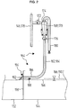
- FIG. 2 is a detailed illustration of this device 164 according to FIG. 1 shown, with reference to which the construction and operation of this device 164 is to be explained.
- this device 164 may also be used in other types of devices that require level control.
- the device 164 comprises a treatment device 168 for treating cleaning fluid from the rinse aid tank 144.
- this treatment device 168 is designed as a centrifugal separator 170 and comprises an inlet 172 for supplying cleaning fluid to be purified, a clean outlet 174 for discharging a purified fraction the cleaning liquid and a dirt drain 176 for discharging a soiled, ie enriched with impurities fraction of the cleaning liquid.
- conditioning device 168 may include other types of processing devices, such as filters or similar devices.
- the feed 172 of the treatment device 168 is connected in the illustrated embodiment via a purge line 178 of the pump flushing system 146 with the rinse tank 144 and is thus supplied in the secondary flow from the pump flushing system 146 via the rinse pump 150 with cleaning fluid.
- the centrifugal separator 170 separates suspended matter which accumulates in the cleaning liquid and thereby improves the washing result.
- the dirt-enriched second fraction of the centrifugal separator 170 which exits at the dirt outlet 176, via a feed line 182 , which may also serve as a sewer line 184, in the illustrated embodiment in one of the upstream in the transport direction 116 rinse zones, in this example, for example, in the main rinsing tank 132, passed.
- a feed line 182 which may also serve as a sewer line 184, in the illustrated embodiment in one of the upstream in the transport direction 116 rinse zones, in this example, for example, in the main rinsing tank 132, passed.
- an introduction can also be made directly into a wastewater system of the cleaning device 110 or into an on-site sewer system.
- only one zone of the cleaning device 110 is equipped with a centrifugal separator 170.
- the delivery line 182 has a substantially horizontally extending control section 186, which is connected via a control port 188 hydraulically connected to the rinse tank 144 or any other storage tank in which the level of the cleaning liquid to be regulated.
- control opening 188 is arranged on the underside of the delivery line 182 in the control section 186, that is to say into the rinse aid tank 144.
- Reference numerals 166 indicate possible levels of cleaning fluid in the rinse tank 144, with the upper of the illustrated levels 166 being at the control port 188, and thus simultaneously characterizing a minimum level 190 below which the level of cleaning fluid in the rinse tank 144 is not likely to decrease should. For example, by moving the conveying line 182 in the vertical direction, this minimum level 190 can be adjusted. Of course, other levels than the displayed levels are 166 in FIG. 2 possible.
- One end 192 of the delivery line 182 projects through an aperture 194 in a wall 196 between the tanks 132 and 144 into the main rinse tank 132 upstream of the rinse tank 144 and forms an outlet port through which liquid from the sewer line 184 enters this main rinse tank 132 can flow.
- the centrifugal separator 170 is supplied in bypass flow from the pump flushing system 146.
- the purified fluid of the first fraction falls back into the rinse tank 144 via the spout 180.
- the wastewater enriched with dirt of the centrifugal separator 170 is conducted via the sewer line 184 in the example into the main flushing zone 130.
- the control portion 186 of the tubular sewer pipe 184 of the apparatus 164 extends at least partially horizontally at the predetermined height of the minimum level 190 through the rinse tank 144.
- this sewer line 184 then exits the rinse tank 144 and directs the wastewater (high dirt content cleaning fluid), for example, into the previous rinse tank, in this case the main rinse tank 132.
- the horizontal control section 186 with the control port 188 of a predetermined size defines Minimum level 190. As long as the level in the rinse tank 144 is at the level of the control port 188 or above, the waste water from the centrifugal separator 170 continues to flow toward the end of the delivery line 192 without hindrance and exits at this end 192. On the other hand, if the level in the rinse tank 144 falls below the predetermined minimum level 190, caused for example by special operating conditions such as water carryover, the control opening 188 on the underside of the horizontal control section 186 becomes free.
- the waste water from the centrifugal separator 170 no longer flows in the direction of the end 192, but falls back into the rinse tank 144 through the control opening 188. This prevents the liquid level in the rinse tank 144 from further decreasing. If the liquid level in the rinse tank 144 is replenished by the regularly inflowing water, for example from a downstream zone of the cleaning device 110, the control opening 188 is closed again, and the wastewater flow from the centrifugal separator 170 again occurs at the outlet opening at the end 192 of the conveying line 182 out.
- the control opening 188 on the underside of the control section 186 which is guided at the level of the minimum level 190, is preferably matched to the size of the tube of the tubular control section 186 and / or the existing during operation volume flow and is for example in a tube with about 20 mm inner diameter and a volume flow of approx. 80 l per minute approx. 20 mm long and approx. 20 mm wide.
- a device 164 according to the invention for level control in particular with a treatment device 168 (with or without centrifugal separator 170), can also be used on throughflow dishwashers with fewer or more tanks than illustrated, or also on a single-tank dishwasher.
- the control section 186 is arranged directly in the rinse tank 144 and is guided at the level of the minimum level 190.
- the hydraulic connection between the rinse aid tank 144 and the control opening 188 or the control section 186 takes place in a different manner.
- the hydraulic connection can be made such that the control section 186 is not guided directly in the rinse tank 144, but in a separate control tank, for example in a sub-tank hydraulically connected to the rinse tank 144.
- the device 164 can also be used for other operations in the cleaning devices 110 in which, for example, by a pump rinse fluid is transported away from a tank and prevents falling below a certain minimum level in the corresponding tank shall be. Accordingly, the device 164 may be used advantageously in connection with the treatment of cleaning fluid, but can be used profitably, inexpensively and in a simple manner for other types of level control.
Landscapes
- Engineering & Computer Science (AREA)
- Textile Engineering (AREA)
- Cleaning By Liquid Or Steam (AREA)
- Washing And Drying Of Tableware (AREA)
Claims (13)
- Dispositif (164) de régulation de niveau d'un fluide dans un réservoir à fluide (122, 132, 144), le réservoir à fluide (122, 132, 144) étant conçu pour accueillir une réserve du fluide, et le dispositif (164) comportant au moins une conduite de refoulement (182) dans laquelle peut s'écouler le fluide, laquelle comporte au moins une ouverture de commande (188) reliée hydrauliquement au réservoir à fluide (122, 132, 144),
caractérisé en ce que la conduite de refoulement (182) possède au moins une portion de commande (186) disposée à l'intérieur du réservoir à fluide (122, 132, 144) ou à l'intérieur d'un réservoir de commande relié hydrauliquement au réservoir à fluide (122, 132, 144), laquelle s'étend au moins partiellement horizontalement et en ce que l'ouverture de commande (188) est disposée dans la portion de commande (186), la portion de commande (186) horizontale définissant avec l'ouverture de commande (188) un niveau minimal (190) du fluide dans le réservoir à fluide ou dans le réservoir de commande et l'ouverture de commande (188), en cas de dépassement du niveau minimal (190) dans le réservoir à fluide (122, 132, 144), empêchant au moins dans une large mesure un écoulement du fluide hors de la conduite de refoulement (182) dans le réservoir à fluide (122, 132, 144) et, en cas de franchissement vers le bas du niveau minimal (190) dans le réservoir à fluide (122, 132, 144), permettant un écoulement du fluide hors de la conduite de refoulement (182) dans le réservoir à fluide (122, 132, 144). - Dispositif (164) selon la revendication 1, l'ouverture de commande (188) étant disposée sur un côté inférieur de la conduite de refoulement (182) dans la portion de commande (186).
- Dispositif (164) selon l'une des revendications précédentes, l'ouverture de commande (188) étant configurée sous la forme d'une ouverture mécaniquement rigide sans éléments structuraux mobiles.
- Dispositif (164) selon l'une des revendications précédentes, comprenant en outre au moins un appareil de refoulement, notamment une pompe (126, 136, 150), l'appareil de refoulement étant conçu pour refouler du fluide hors du réservoir à fluide (122, 132, 144) dans la conduite de refoulement (182).
- Dispositif de nettoyage (110) destiné à nettoyer au moins un produit à nettoyer, notamment lave-vaisselle, comprenant au moins un réservoir de stockage (122, 132, 144) destiné à accueillir un liquide de nettoyage, comprenant en outre au moins un dispositif (164) selon l'une des revendications précédentes servant à la régulation du niveau dans le réservoir de stockage (122, 132, 144).
- Dispositif de nettoyage (110) selon la revendication précédente, l'ouverture de commande (188) étant reliée hydrauliquement au réservoir de stockage (122, 132, 144), la conduite de refoulement (182) étant reliée à un réservoir supplémentaire (122, 132, 144) ou un système d'évacuation.
- Dispositif de nettoyage (110) selon la revendication précédente, le dispositif de nettoyage (110) comportant au moins deux zones de nettoyage (120, 130, 138, 140, 142), le dispositif de nettoyage (110) comportant au moins un dispositif de transport (112) destiné à transporter le produit à nettoyer dans une direction de transport (116) à travers les au moins deux zones de nettoyage (120, 130, 138, 140, 142), le réservoir de stockage (122, 132, 144) étant associé à au moins une première zone de nettoyage (120, 130, 138, 140, 142), le dispositif de nettoyage (110) étant conçu pour refouler le liquide de nettoyage du réservoir de stockage (122, 132, 144) dans la conduite de refoulement (182), le réservoir supplémentaire (122, 132, 144) étant associé à au moins une deuxième zone de nettoyage (120, 130, 138, 140, 142) placée en amont dans la direction de transport (116).
- Dispositif de nettoyage (110) selon l'une des revendications précédentes concernant un dispositif de nettoyage (110), comprenant en outre au moins un dispositif de préparation (168) destiné à éliminer des impuretés du liquide de nettoyage, le dispositif de préparation (168) étant relié au dispositif (164) de régulation de niveau.
- Dispositif de nettoyage (110) selon la revendication précédente, le dispositif de préparation (168) possédant au moins un écoulement des déchets (176) destiné à l'évacuation d'une fraction polluée du liquide de nettoyage et au moins un écoulement propre (174) destiné à l'évacuation d'une fraction nettoyée du liquide de nettoyage, l'écoulement des déchets (176) étant relié à la conduite de refoulement (182) et l'écoulement propre (174) étant disposé de manière à permettre une affluence de la fraction nettoyée dans le réservoir de stockage (122, 132, 144).
- Dispositif de nettoyage (110) selon l'une des deux revendications précédentes, le dispositif de préparation (168) possédant au moins une arrivée (172) destinée à l'acheminement de liquide de nettoyage à nettoyer, l'arrivée (172) étant reliée au réservoir de stockage (122, 132, 144).
- Dispositif de nettoyage (110) selon la revendication précédente, le dispositif de nettoyage (110) possédant au moins un système de rinçage (124, 134, 146, 148) destiné à charger le produit à nettoyer avec le liquide de nettoyage, notamment un système à buses, le système de rinçage (124, 134, 146, 148) pouvant être chargé avec le liquide de nettoyage depuis le réservoir de stockage (122, 132, 144) par le biais d'une conduite de rinçage (178), l'arrivée (172) étant reliée à la conduite de rinçage (178).
- Dispositif de nettoyage (110) selon l'une des quatre revendications précédentes, le dispositif de préparation (168) possédant au moins un collecteur centrifuge (170).
- Procédé de régulation de niveau dans un réservoir à fluide (122, 132, 144) en utilisant un dispositif (164) selon l'une des revendications précédentes, concernant un dispositif (164) de régulation de niveau dans un réservoir à fluide (122, 132, 144).
Applications Claiming Priority (1)
| Application Number | Priority Date | Filing Date | Title |
|---|---|---|---|
| DE200810022960 DE102008022960A1 (de) | 2008-05-09 | 2008-05-09 | Schmutzabscheider-Einrichtung mit Niveauregelung |
Publications (2)
| Publication Number | Publication Date |
|---|---|
| EP2116168A1 EP2116168A1 (fr) | 2009-11-11 |
| EP2116168B1 true EP2116168B1 (fr) | 2019-01-30 |
Family
ID=41050366
Family Applications (1)
| Application Number | Title | Priority Date | Filing Date |
|---|---|---|---|
| EP09006072.4A Active EP2116168B1 (fr) | 2008-05-09 | 2009-05-04 | Dispositif de séparation d'impuretés doté d'un réglage de niveau |
Country Status (5)
| Country | Link |
|---|---|
| US (1) | US8397735B2 (fr) |
| EP (1) | EP2116168B1 (fr) |
| CN (1) | CN101574250B (fr) |
| DE (1) | DE102008022960A1 (fr) |
| RU (1) | RU2494668C2 (fr) |
Families Citing this family (3)
| Publication number | Priority date | Publication date | Assignee | Title |
|---|---|---|---|---|
| DE102014000448A1 (de) | 2014-01-10 | 2015-07-16 | Meiko Maschinenbau Gmbh & Co. Kg | Transportspülmaschine mit mehreren Behandlungszonen |
| DE102015206338A1 (de) * | 2015-04-09 | 2016-10-13 | Illinois Tool Works Inc. | Transportspülmaschine sowie Verfahren zum Betreiben einer Transportspülmaschine |
| DE102019206978B4 (de) * | 2019-05-14 | 2020-12-17 | Meiko Maschinenbau Gmbh & Co. Kg | Geschirrspülmaschine zum Einsatz in einem Verkehrsmittel |
Citations (2)
| Publication number | Priority date | Publication date | Assignee | Title |
|---|---|---|---|---|
| FR2305159A1 (fr) * | 1975-03-25 | 1976-10-22 | Seb Sa | Machine electro-domestique a laver les verres et objets analogues |
| EP0546434A1 (fr) * | 1991-12-12 | 1993-06-16 | AEG Hausgeräte GmbH | Réglage du niveau pour une machine à laver la vaisselle |
Family Cites Families (13)
| Publication number | Priority date | Publication date | Assignee | Title |
|---|---|---|---|---|
| NL126434C (fr) | 1964-01-03 | 1900-01-01 | ||
| AT290777B (de) * | 1968-06-18 | 1971-06-25 | Winterhalter Kg Karl | Geschirrspülmaschine |
| DE6602300U (de) | 1968-06-18 | 1969-05-29 | Karl Winterhalter K G | Geschirrspuelmaschine |
| DE1965828C3 (de) | 1969-12-20 | 1973-11-22 | Karl Winterhalter Kg, 7996 Meckenbeuren | Automatische Gerschirrspülmaschine mit Fliehkraftabscheider |
| DE2716252C2 (de) * | 1977-04-13 | 1983-04-07 | Bosch-Siemens Hausgeräte GmbH, 7000 Stuttgart | Geschirrspül- oder Waschmaschine mit einer Einrichtung zum Abgeben einer in einem Sammelbehälter abgemessenen Wassermenge |
| DE4231849C2 (de) * | 1991-12-20 | 2003-05-08 | Bsh Bosch Siemens Hausgeraete | Wasch- oder Geschirrspülmaschine mit einem Druckgeber als Wasserstandregler |
| IT1273347B (it) * | 1994-02-28 | 1997-07-08 | Candy Spa | Dispositivo per il controllo del livello del liquido di lavaggio in una lavastoviglie |
| IT1271021B (it) * | 1994-10-20 | 1997-05-26 | Candy Spa | Dispositivo di controllo del carico di liquido di lavaggio in una lavastoviglie |
| DE19836739A1 (de) | 1998-08-13 | 2000-02-17 | Meiko Maschinenbau Gmbh & Co | Geschirrspülmaschine |
| BR0100716A (pt) * | 2001-02-15 | 2002-11-05 | Multibras Eletrodomesticos Sa | Dispositivo indicador de nìvel de água para lava-louça |
| DE102005030720A1 (de) * | 2005-07-01 | 2007-01-04 | Premark Feg L.L.C., Wilmington | Transportgeschirrspülmaschine und Betriebsverfahren hierfür |
| DE102005035764A1 (de) * | 2005-07-29 | 2007-02-01 | Premark Feg L.L.C., Wilmington | Transportgeschirrspülmaschine und Betriebsverfahren hierfür |
| KR101266870B1 (ko) * | 2006-07-12 | 2013-05-23 | 삼성전자주식회사 | 식기세척기 |
-
2008
- 2008-05-09 DE DE200810022960 patent/DE102008022960A1/de not_active Withdrawn
-
2009
- 2009-05-04 CN CN200910137650XA patent/CN101574250B/zh not_active Expired - Fee Related
- 2009-05-04 EP EP09006072.4A patent/EP2116168B1/fr active Active
- 2009-05-08 RU RU2009117604/12A patent/RU2494668C2/ru active
- 2009-05-11 US US12/463,643 patent/US8397735B2/en not_active Expired - Fee Related
Patent Citations (2)
| Publication number | Priority date | Publication date | Assignee | Title |
|---|---|---|---|---|
| FR2305159A1 (fr) * | 1975-03-25 | 1976-10-22 | Seb Sa | Machine electro-domestique a laver les verres et objets analogues |
| EP0546434A1 (fr) * | 1991-12-12 | 1993-06-16 | AEG Hausgeräte GmbH | Réglage du niveau pour une machine à laver la vaisselle |
Also Published As
| Publication number | Publication date |
|---|---|
| RU2009117604A (ru) | 2010-11-20 |
| CN101574250B (zh) | 2011-12-21 |
| US20090277511A1 (en) | 2009-11-12 |
| EP2116168A1 (fr) | 2009-11-11 |
| RU2494668C2 (ru) | 2013-10-10 |
| DE102008022960A1 (de) | 2009-11-12 |
| US8397735B2 (en) | 2013-03-19 |
| CN101574250A (zh) | 2009-11-11 |
Similar Documents
| Publication | Publication Date | Title |
|---|---|---|
| DE102008037683B4 (de) | Transportspülmaschine sowie Verfahren zum Betreiben einer Transportspülmaschine | |
| EP1953458B1 (fr) | Procédé de nettoyage d'un appareil de cuisson | |
| DE102009048810B4 (de) | Spülmaschine mit Schmutzaustragsystem | |
| DE102012212638C5 (de) | Spülmaschine sowie Verfahren zum Betreiben einer Spülmaschine | |
| EP2072000B1 (fr) | Lave-vaisselle en forme d'automate de programmation et son procédé de fonctionnement | |
| DE102008057178A1 (de) | Anlage zum Spülen von Spülgut und Verfahren zum Betreiben einer solchen Anlage | |
| DE102012211442A1 (de) | Reinigungsvorrichtung mit individuell schaltbarem Klarspül-Düsensystem | |
| DE102010062457A1 (de) | Beladevorrichtung für eine Transportspülmaschine | |
| EP1835840A1 (fr) | Lave-vaisselle à plusieurs cuves, équipé d'un dispositif de lavage à contre-courant | |
| DE102007009252A1 (de) | Verfahren zum Betrieb einer Durchlaufgeschirrspülmaschine | |
| DE102004030003A1 (de) | Spülmaschinen-Betriebsverfahren und Transportspülmaschine | |
| DE102010053051A1 (de) | Spülmaschine mit Umkehr-Osmose-Anlage | |
| DE102004030014A1 (de) | Spülmaschinen-Betriebsverfahren und Transportspülmaschine | |
| DE102004030015A1 (de) | Spülmaschinen-Betriebsverfahren und Transportspülmaschine | |
| DE102016107054A1 (de) | Transportspülmaschine zum reinigen von spülgut | |
| EP2116168B1 (fr) | Dispositif de séparation d'impuretés doté d'un réglage de niveau | |
| EP4306030B1 (fr) | Lave-vaisselle avec système d'évacuation des saletés | |
| DE102009032964A1 (de) | Verfahren zum Betrieb einer Mehrtankgeschirrspülmaschine | |
| DE102011017294A1 (de) | Transportspülmaschine mit Sonderbehandlungszonen | |
| DE102010063711A1 (de) | Spülmaschine mit automatischer Schmutzaustragung | |
| EP1637059B1 (fr) | Installation de lave-vaiselle | |
| EP1815779B1 (fr) | Machine à laver la vaisselle à bande | |
| DE102010005533B4 (de) | Transportspülmaschine mit optimierter Klarspülerdosierung sowie Verfahren zum Betreiben einer solchen Transportspülmaschine | |
| DE102004030001A1 (de) | Spülmaschinen-Betriebsverfahren und Transportspülmaschine | |
| DE102006026817A1 (de) | Gewerbliche Geschirrspülmaschine in Form eines Programmautomaten |
Legal Events
| Date | Code | Title | Description |
|---|---|---|---|
| PUAI | Public reference made under article 153(3) epc to a published international application that has entered the european phase |
Free format text: ORIGINAL CODE: 0009012 |
|
| AK | Designated contracting states |
Kind code of ref document: A1 Designated state(s): AT BE BG CH CY CZ DE DK EE ES FI FR GB GR HR HU IE IS IT LI LT LU LV MC MK MT NL NO PL PT RO SE SI SK TR |
|
| 17P | Request for examination filed |
Effective date: 20091202 |
|
| 17Q | First examination report despatched |
Effective date: 20150428 |
|
| GRAP | Despatch of communication of intention to grant a patent |
Free format text: ORIGINAL CODE: EPIDOSNIGR1 |
|
| STAA | Information on the status of an ep patent application or granted ep patent |
Free format text: STATUS: GRANT OF PATENT IS INTENDED |
|
| INTG | Intention to grant announced |
Effective date: 20180709 |
|
| GRAJ | Information related to disapproval of communication of intention to grant by the applicant or resumption of examination proceedings by the epo deleted |
Free format text: ORIGINAL CODE: EPIDOSDIGR1 |
|
| STAA | Information on the status of an ep patent application or granted ep patent |
Free format text: STATUS: EXAMINATION IS IN PROGRESS |
|
| GRAP | Despatch of communication of intention to grant a patent |
Free format text: ORIGINAL CODE: EPIDOSNIGR1 |
|
| STAA | Information on the status of an ep patent application or granted ep patent |
Free format text: STATUS: GRANT OF PATENT IS INTENDED |
|
| RIN1 | Information on inventor provided before grant (corrected) |
Inventor name: ROEDERER, THOMAS Inventor name: FRANZ, JOACHIM DIPL.-ING. (FH) |
|
| INTC | Intention to grant announced (deleted) | ||
| INTG | Intention to grant announced |
Effective date: 20180830 |
|
| GRAS | Grant fee paid |
Free format text: ORIGINAL CODE: EPIDOSNIGR3 |
|
| GRAA | (expected) grant |
Free format text: ORIGINAL CODE: 0009210 |
|
| STAA | Information on the status of an ep patent application or granted ep patent |
Free format text: STATUS: THE PATENT HAS BEEN GRANTED |
|
| AK | Designated contracting states |
Kind code of ref document: B1 Designated state(s): AT BE BG CH CY CZ DE DK EE ES FI FR GB GR HR HU IE IS IT LI LT LU LV MC MK MT NL NO PL PT RO SE SI SK TR |
|
| REG | Reference to a national code |
Ref country code: GB Ref legal event code: FG4D Free format text: NOT ENGLISH |
|
| REG | Reference to a national code |
Ref country code: CH Ref legal event code: EP |
|
| REG | Reference to a national code |
Ref country code: AT Ref legal event code: REF Ref document number: 1092572 Country of ref document: AT Kind code of ref document: T Effective date: 20190215 |
|
| REG | Reference to a national code |
Ref country code: IE Ref legal event code: FG4D Free format text: LANGUAGE OF EP DOCUMENT: GERMAN |
|
| REG | Reference to a national code |
Ref country code: DE Ref legal event code: R096 Ref document number: 502009015601 Country of ref document: DE |
|
| REG | Reference to a national code |
Ref country code: CH Ref legal event code: NV Representative=s name: SCHMAUDER AND PARTNER AG PATENT- UND MARKENANW, CH |
|
| REG | Reference to a national code |
Ref country code: LT Ref legal event code: MG4D |
|
| REG | Reference to a national code |
Ref country code: NL Ref legal event code: MP Effective date: 20190130 |
|
| PG25 | Lapsed in a contracting state [announced via postgrant information from national office to epo] |
Ref country code: ES Free format text: LAPSE BECAUSE OF FAILURE TO SUBMIT A TRANSLATION OF THE DESCRIPTION OR TO PAY THE FEE WITHIN THE PRESCRIBED TIME-LIMIT Effective date: 20190130 Ref country code: NL Free format text: LAPSE BECAUSE OF FAILURE TO SUBMIT A TRANSLATION OF THE DESCRIPTION OR TO PAY THE FEE WITHIN THE PRESCRIBED TIME-LIMIT Effective date: 20190130 Ref country code: PL Free format text: LAPSE BECAUSE OF FAILURE TO SUBMIT A TRANSLATION OF THE DESCRIPTION OR TO PAY THE FEE WITHIN THE PRESCRIBED TIME-LIMIT Effective date: 20190130 Ref country code: FI Free format text: LAPSE BECAUSE OF FAILURE TO SUBMIT A TRANSLATION OF THE DESCRIPTION OR TO PAY THE FEE WITHIN THE PRESCRIBED TIME-LIMIT Effective date: 20190130 Ref country code: LT Free format text: LAPSE BECAUSE OF FAILURE TO SUBMIT A TRANSLATION OF THE DESCRIPTION OR TO PAY THE FEE WITHIN THE PRESCRIBED TIME-LIMIT Effective date: 20190130 Ref country code: SE Free format text: LAPSE BECAUSE OF FAILURE TO SUBMIT A TRANSLATION OF THE DESCRIPTION OR TO PAY THE FEE WITHIN THE PRESCRIBED TIME-LIMIT Effective date: 20190130 Ref country code: PT Free format text: LAPSE BECAUSE OF FAILURE TO SUBMIT A TRANSLATION OF THE DESCRIPTION OR TO PAY THE FEE WITHIN THE PRESCRIBED TIME-LIMIT Effective date: 20190530 Ref country code: NO Free format text: LAPSE BECAUSE OF FAILURE TO SUBMIT A TRANSLATION OF THE DESCRIPTION OR TO PAY THE FEE WITHIN THE PRESCRIBED TIME-LIMIT Effective date: 20190430 |
|
| PG25 | Lapsed in a contracting state [announced via postgrant information from national office to epo] |
Ref country code: BG Free format text: LAPSE BECAUSE OF FAILURE TO SUBMIT A TRANSLATION OF THE DESCRIPTION OR TO PAY THE FEE WITHIN THE PRESCRIBED TIME-LIMIT Effective date: 20190430 Ref country code: IS Free format text: LAPSE BECAUSE OF FAILURE TO SUBMIT A TRANSLATION OF THE DESCRIPTION OR TO PAY THE FEE WITHIN THE PRESCRIBED TIME-LIMIT Effective date: 20190530 Ref country code: HR Free format text: LAPSE BECAUSE OF FAILURE TO SUBMIT A TRANSLATION OF THE DESCRIPTION OR TO PAY THE FEE WITHIN THE PRESCRIBED TIME-LIMIT Effective date: 20190130 Ref country code: LV Free format text: LAPSE BECAUSE OF FAILURE TO SUBMIT A TRANSLATION OF THE DESCRIPTION OR TO PAY THE FEE WITHIN THE PRESCRIBED TIME-LIMIT Effective date: 20190130 Ref country code: GR Free format text: LAPSE BECAUSE OF FAILURE TO SUBMIT A TRANSLATION OF THE DESCRIPTION OR TO PAY THE FEE WITHIN THE PRESCRIBED TIME-LIMIT Effective date: 20190501 |
|
| PG25 | Lapsed in a contracting state [announced via postgrant information from national office to epo] |
Ref country code: SK Free format text: LAPSE BECAUSE OF FAILURE TO SUBMIT A TRANSLATION OF THE DESCRIPTION OR TO PAY THE FEE WITHIN THE PRESCRIBED TIME-LIMIT Effective date: 20190130 Ref country code: RO Free format text: LAPSE BECAUSE OF FAILURE TO SUBMIT A TRANSLATION OF THE DESCRIPTION OR TO PAY THE FEE WITHIN THE PRESCRIBED TIME-LIMIT Effective date: 20190130 Ref country code: CZ Free format text: LAPSE BECAUSE OF FAILURE TO SUBMIT A TRANSLATION OF THE DESCRIPTION OR TO PAY THE FEE WITHIN THE PRESCRIBED TIME-LIMIT Effective date: 20190130 Ref country code: EE Free format text: LAPSE BECAUSE OF FAILURE TO SUBMIT A TRANSLATION OF THE DESCRIPTION OR TO PAY THE FEE WITHIN THE PRESCRIBED TIME-LIMIT Effective date: 20190130 Ref country code: DK Free format text: LAPSE BECAUSE OF FAILURE TO SUBMIT A TRANSLATION OF THE DESCRIPTION OR TO PAY THE FEE WITHIN THE PRESCRIBED TIME-LIMIT Effective date: 20190130 |
|
| REG | Reference to a national code |
Ref country code: DE Ref legal event code: R097 Ref document number: 502009015601 Country of ref document: DE |
|
| PLBE | No opposition filed within time limit |
Free format text: ORIGINAL CODE: 0009261 |
|
| STAA | Information on the status of an ep patent application or granted ep patent |
Free format text: STATUS: NO OPPOSITION FILED WITHIN TIME LIMIT |
|
| 26N | No opposition filed |
Effective date: 20191031 |
|
| PG25 | Lapsed in a contracting state [announced via postgrant information from national office to epo] |
Ref country code: MC Free format text: LAPSE BECAUSE OF FAILURE TO SUBMIT A TRANSLATION OF THE DESCRIPTION OR TO PAY THE FEE WITHIN THE PRESCRIBED TIME-LIMIT Effective date: 20190130 |
|
| REG | Reference to a national code |
Ref country code: BE Ref legal event code: MM Effective date: 20190531 |
|
| PG25 | Lapsed in a contracting state [announced via postgrant information from national office to epo] |
Ref country code: SI Free format text: LAPSE BECAUSE OF FAILURE TO SUBMIT A TRANSLATION OF THE DESCRIPTION OR TO PAY THE FEE WITHIN THE PRESCRIBED TIME-LIMIT Effective date: 20190130 Ref country code: LU Free format text: LAPSE BECAUSE OF NON-PAYMENT OF DUE FEES Effective date: 20190504 |
|
| PG25 | Lapsed in a contracting state [announced via postgrant information from national office to epo] |
Ref country code: TR Free format text: LAPSE BECAUSE OF FAILURE TO SUBMIT A TRANSLATION OF THE DESCRIPTION OR TO PAY THE FEE WITHIN THE PRESCRIBED TIME-LIMIT Effective date: 20190130 |
|
| PG25 | Lapsed in a contracting state [announced via postgrant information from national office to epo] |
Ref country code: IE Free format text: LAPSE BECAUSE OF NON-PAYMENT OF DUE FEES Effective date: 20190504 |
|
| PG25 | Lapsed in a contracting state [announced via postgrant information from national office to epo] |
Ref country code: BE Free format text: LAPSE BECAUSE OF NON-PAYMENT OF DUE FEES Effective date: 20190531 |
|
| REG | Reference to a national code |
Ref country code: AT Ref legal event code: MM01 Ref document number: 1092572 Country of ref document: AT Kind code of ref document: T Effective date: 20190504 |
|
| PG25 | Lapsed in a contracting state [announced via postgrant information from national office to epo] |
Ref country code: AT Free format text: LAPSE BECAUSE OF NON-PAYMENT OF DUE FEES Effective date: 20190504 |
|
| PG25 | Lapsed in a contracting state [announced via postgrant information from national office to epo] |
Ref country code: CY Free format text: LAPSE BECAUSE OF FAILURE TO SUBMIT A TRANSLATION OF THE DESCRIPTION OR TO PAY THE FEE WITHIN THE PRESCRIBED TIME-LIMIT Effective date: 20190130 |
|
| PG25 | Lapsed in a contracting state [announced via postgrant information from national office to epo] |
Ref country code: HU Free format text: LAPSE BECAUSE OF FAILURE TO SUBMIT A TRANSLATION OF THE DESCRIPTION OR TO PAY THE FEE WITHIN THE PRESCRIBED TIME-LIMIT; INVALID AB INITIO Effective date: 20090504 Ref country code: MT Free format text: LAPSE BECAUSE OF FAILURE TO SUBMIT A TRANSLATION OF THE DESCRIPTION OR TO PAY THE FEE WITHIN THE PRESCRIBED TIME-LIMIT Effective date: 20190130 |
|
| PG25 | Lapsed in a contracting state [announced via postgrant information from national office to epo] |
Ref country code: MK Free format text: LAPSE BECAUSE OF FAILURE TO SUBMIT A TRANSLATION OF THE DESCRIPTION OR TO PAY THE FEE WITHIN THE PRESCRIBED TIME-LIMIT Effective date: 20190130 |
|
| P01 | Opt-out of the competence of the unified patent court (upc) registered |
Effective date: 20230525 |
|
| PGFP | Annual fee paid to national office [announced via postgrant information from national office to epo] |
Ref country code: GB Payment date: 20240516 Year of fee payment: 16 |
|
| PGFP | Annual fee paid to national office [announced via postgrant information from national office to epo] |
Ref country code: DE Payment date: 20240523 Year of fee payment: 16 |
|
| PGFP | Annual fee paid to national office [announced via postgrant information from national office to epo] |
Ref country code: CH Payment date: 20240602 Year of fee payment: 16 |
|
| PGFP | Annual fee paid to national office [announced via postgrant information from national office to epo] |
Ref country code: FR Payment date: 20240522 Year of fee payment: 16 |
|
| PGFP | Annual fee paid to national office [announced via postgrant information from national office to epo] |
Ref country code: IT Payment date: 20240529 Year of fee payment: 16 |
|
| REG | Reference to a national code |
Ref country code: DE Ref legal event code: R119 Ref document number: 502009015601 Country of ref document: DE |
|
| REG | Reference to a national code |
Ref country code: CH Ref legal event code: H13 Free format text: ST27 STATUS EVENT CODE: U-0-0-H10-H13 (AS PROVIDED BY THE NATIONAL OFFICE) Effective date: 20251223 |
|
| PG25 | Lapsed in a contracting state [announced via postgrant information from national office to epo] |
Ref country code: CH Free format text: LAPSE BECAUSE OF NON-PAYMENT OF DUE FEES Effective date: 20250531 |
|
| GBPC | Gb: european patent ceased through non-payment of renewal fee |
Effective date: 20250504 |
|
| PG25 | Lapsed in a contracting state [announced via postgrant information from national office to epo] |
Ref country code: GB Free format text: LAPSE BECAUSE OF NON-PAYMENT OF DUE FEES Effective date: 20250504 |
|
| PG25 | Lapsed in a contracting state [announced via postgrant information from national office to epo] |
Ref country code: DE Free format text: LAPSE BECAUSE OF NON-PAYMENT OF DUE FEES Effective date: 20251202 |
|
| PG25 | Lapsed in a contracting state [announced via postgrant information from national office to epo] |
Ref country code: IT Free format text: LAPSE BECAUSE OF NON-PAYMENT OF DUE FEES Effective date: 20250504 |
|
| PG25 | Lapsed in a contracting state [announced via postgrant information from national office to epo] |
Ref country code: FR Free format text: LAPSE BECAUSE OF NON-PAYMENT OF DUE FEES Effective date: 20250531 |