EP2116340B1 - Synchroner Roboterbetrieb auf einer Struktur mit begrenztem Raum - Google Patents
Synchroner Roboterbetrieb auf einer Struktur mit begrenztem Raum Download PDFInfo
- Publication number
- EP2116340B1 EP2116340B1 EP09155313.1A EP09155313A EP2116340B1 EP 2116340 B1 EP2116340 B1 EP 2116340B1 EP 09155313 A EP09155313 A EP 09155313A EP 2116340 B1 EP2116340 B1 EP 2116340B1
- Authority
- EP
- European Patent Office
- Prior art keywords
- end effector
- location
- robotic
- confined space
- robotic system
- Prior art date
- Legal status (The legal status is an assumption and is not a legal conclusion. Google has not performed a legal analysis and makes no representation as to the accuracy of the status listed.)
- Active
Links
Images



Classifications
-
- B—PERFORMING OPERATIONS; TRANSPORTING
- B25—HAND TOOLS; PORTABLE POWER-DRIVEN TOOLS; MANIPULATORS
- B25J—MANIPULATORS; CHAMBERS PROVIDED WITH MANIPULATION DEVICES
- B25J9/00—Program-controlled manipulators
- B25J9/16—Program controls
- B25J9/1679—Program controls characterised by the tasks executed
- B25J9/1682—Dual arm manipulator; Coordination of several manipulators
-
- B—PERFORMING OPERATIONS; TRANSPORTING
- B21—MECHANICAL METAL-WORKING WITHOUT ESSENTIALLY REMOVING MATERIAL; PUNCHING METAL
- B21J—FORGING; HAMMERING; PRESSING METAL; RIVETING; FORGE FURNACES
- B21J15/00—Riveting
- B21J15/10—Riveting machines
- B21J15/14—Riveting machines specially adapted for riveting specific articles, e.g. brake lining machines
- B21J15/142—Aerospace structures
-
- G—PHYSICS
- G05—CONTROLLING; REGULATING
- G05B—CONTROL OR REGULATING SYSTEMS IN GENERAL; FUNCTIONAL ELEMENTS OF SUCH SYSTEMS; MONITORING OR TESTING ARRANGEMENTS FOR SUCH SYSTEMS OR ELEMENTS
- G05B2219/00—Program-control systems
- G05B2219/30—Nc systems
- G05B2219/32—Operator till task planning
- G05B2219/32285—Multi manipulator assembly cell
-
- G—PHYSICS
- G05—CONTROLLING; REGULATING
- G05B—CONTROL OR REGULATING SYSTEMS IN GENERAL; FUNCTIONAL ELEMENTS OF SUCH SYSTEMS; MONITORING OR TESTING ARRANGEMENTS FOR SUCH SYSTEMS OR ELEMENTS
- G05B2219/00—Program-control systems
- G05B2219/30—Nc systems
- G05B2219/39—Robotics, robotics to robotics hand
- G05B2219/39121—Two manipulators operate on same object
-
- G—PHYSICS
- G05—CONTROLLING; REGULATING
- G05B—CONTROL OR REGULATING SYSTEMS IN GENERAL; FUNCTIONAL ELEMENTS OF SUCH SYSTEMS; MONITORING OR TESTING ARRANGEMENTS FOR SUCH SYSTEMS OR ELEMENTS
- G05B2219/00—Program-control systems
- G05B2219/30—Nc systems
- G05B2219/39—Robotics, robotics to robotics hand
- G05B2219/39122—Follower, follower mirrors leader, leader
-
- G—PHYSICS
- G05—CONTROLLING; REGULATING
- G05B—CONTROL OR REGULATING SYSTEMS IN GENERAL; FUNCTIONAL ELEMENTS OF SUCH SYSTEMS; MONITORING OR TESTING ARRANGEMENTS FOR SUCH SYSTEMS OR ELEMENTS
- G05B2219/00—Program-control systems
- G05B2219/30—Nc systems
- G05B2219/39—Robotics, robotics to robotics hand
- G05B2219/39141—Follower program has no taught positions, receives position from leader, convert from leader
-
- G—PHYSICS
- G05—CONTROLLING; REGULATING
- G05B—CONTROL OR REGULATING SYSTEMS IN GENERAL; FUNCTIONAL ELEMENTS OF SUCH SYSTEMS; MONITORING OR TESTING ARRANGEMENTS FOR SUCH SYSTEMS OR ELEMENTS
- G05B2219/00—Program-control systems
- G05B2219/30—Nc systems
- G05B2219/45—Nc applications
- G05B2219/45059—Drilling robot
-
- G—PHYSICS
- G05—CONTROLLING; REGULATING
- G05B—CONTROL OR REGULATING SYSTEMS IN GENERAL; FUNCTIONAL ELEMENTS OF SUCH SYSTEMS; MONITORING OR TESTING ARRANGEMENTS FOR SUCH SYSTEMS OR ELEMENTS
- G05B2219/00—Program-control systems
- G05B2219/30—Nc systems
- G05B2219/45—Nc applications
- G05B2219/45064—Assembly robot
-
- G—PHYSICS
- G05—CONTROLLING; REGULATING
- G05B—CONTROL OR REGULATING SYSTEMS IN GENERAL; FUNCTIONAL ELEMENTS OF SUCH SYSTEMS; MONITORING OR TESTING ARRANGEMENTS FOR SUCH SYSTEMS OR ELEMENTS
- G05B2219/00—Program-control systems
- G05B2219/30—Nc systems
- G05B2219/45—Nc applications
- G05B2219/45126—Riveting machine
-
- Y—GENERAL TAGGING OF NEW TECHNOLOGICAL DEVELOPMENTS; GENERAL TAGGING OF CROSS-SECTIONAL TECHNOLOGIES SPANNING OVER SEVERAL SECTIONS OF THE IPC; TECHNICAL SUBJECTS COVERED BY FORMER USPC CROSS-REFERENCE ART COLLECTIONS [XRACs] AND DIGESTS
- Y10—TECHNICAL SUBJECTS COVERED BY FORMER USPC
- Y10T—TECHNICAL SUBJECTS COVERED BY FORMER US CLASSIFICATION
- Y10T29/00—Metal working
- Y10T29/49—Method of mechanical manufacture
- Y10T29/49826—Assembling or joining
-
- Y—GENERAL TAGGING OF NEW TECHNOLOGICAL DEVELOPMENTS; GENERAL TAGGING OF CROSS-SECTIONAL TECHNOLOGIES SPANNING OVER SEVERAL SECTIONS OF THE IPC; TECHNICAL SUBJECTS COVERED BY FORMER USPC CROSS-REFERENCE ART COLLECTIONS [XRACs] AND DIGESTS
- Y10—TECHNICAL SUBJECTS COVERED BY FORMER USPC
- Y10T—TECHNICAL SUBJECTS COVERED BY FORMER US CLASSIFICATION
- Y10T29/00—Metal working
- Y10T29/49—Method of mechanical manufacture
- Y10T29/49826—Assembling or joining
- Y10T29/49908—Joining by deforming
- Y10T29/49938—Radially expanding part in cavity, aperture, or hollow body
- Y10T29/49943—Riveting
-
- Y—GENERAL TAGGING OF NEW TECHNOLOGICAL DEVELOPMENTS; GENERAL TAGGING OF CROSS-SECTIONAL TECHNOLOGIES SPANNING OVER SEVERAL SECTIONS OF THE IPC; TECHNICAL SUBJECTS COVERED BY FORMER USPC CROSS-REFERENCE ART COLLECTIONS [XRACs] AND DIGESTS
- Y10—TECHNICAL SUBJECTS COVERED BY FORMER USPC
- Y10T—TECHNICAL SUBJECTS COVERED BY FORMER US CLASSIFICATION
- Y10T29/00—Metal working
- Y10T29/49—Method of mechanical manufacture
- Y10T29/49826—Assembling or joining
- Y10T29/49947—Assembling or joining by applying separate fastener
- Y10T29/49948—Multipart cooperating fastener [e.g., bolt and nut]
-
- Y—GENERAL TAGGING OF NEW TECHNOLOGICAL DEVELOPMENTS; GENERAL TAGGING OF CROSS-SECTIONAL TECHNOLOGIES SPANNING OVER SEVERAL SECTIONS OF THE IPC; TECHNICAL SUBJECTS COVERED BY FORMER USPC CROSS-REFERENCE ART COLLECTIONS [XRACs] AND DIGESTS
- Y10—TECHNICAL SUBJECTS COVERED BY FORMER USPC
- Y10T—TECHNICAL SUBJECTS COVERED BY FORMER US CLASSIFICATION
- Y10T29/00—Metal working
- Y10T29/49—Method of mechanical manufacture
- Y10T29/49826—Assembling or joining
- Y10T29/49947—Assembling or joining by applying separate fastener
- Y10T29/49954—Fastener deformed after application
- Y10T29/49956—Riveting
-
- Y—GENERAL TAGGING OF NEW TECHNOLOGICAL DEVELOPMENTS; GENERAL TAGGING OF CROSS-SECTIONAL TECHNOLOGIES SPANNING OVER SEVERAL SECTIONS OF THE IPC; TECHNICAL SUBJECTS COVERED BY FORMER USPC CROSS-REFERENCE ART COLLECTIONS [XRACs] AND DIGESTS
- Y10—TECHNICAL SUBJECTS COVERED BY FORMER USPC
- Y10T—TECHNICAL SUBJECTS COVERED BY FORMER US CLASSIFICATION
- Y10T29/00—Metal working
- Y10T29/51—Plural diverse manufacturing apparatus including means for metal shaping or assembling
-
- Y—GENERAL TAGGING OF NEW TECHNOLOGICAL DEVELOPMENTS; GENERAL TAGGING OF CROSS-SECTIONAL TECHNOLOGIES SPANNING OVER SEVERAL SECTIONS OF THE IPC; TECHNICAL SUBJECTS COVERED BY FORMER USPC CROSS-REFERENCE ART COLLECTIONS [XRACs] AND DIGESTS
- Y10—TECHNICAL SUBJECTS COVERED BY FORMER USPC
- Y10T—TECHNICAL SUBJECTS COVERED BY FORMER US CLASSIFICATION
- Y10T29/00—Metal working
- Y10T29/51—Plural diverse manufacturing apparatus including means for metal shaping or assembling
- Y10T29/5124—Plural diverse manufacturing apparatus including means for metal shaping or assembling with means to feed work intermittently from one tool station to another
-
- Y—GENERAL TAGGING OF NEW TECHNOLOGICAL DEVELOPMENTS; GENERAL TAGGING OF CROSS-SECTIONAL TECHNOLOGIES SPANNING OVER SEVERAL SECTIONS OF THE IPC; TECHNICAL SUBJECTS COVERED BY FORMER USPC CROSS-REFERENCE ART COLLECTIONS [XRACs] AND DIGESTS
- Y10—TECHNICAL SUBJECTS COVERED BY FORMER USPC
- Y10T—TECHNICAL SUBJECTS COVERED BY FORMER US CLASSIFICATION
- Y10T29/00—Metal working
- Y10T29/52—Plural diverse manufacturing apparatus
-
- Y—GENERAL TAGGING OF NEW TECHNOLOGICAL DEVELOPMENTS; GENERAL TAGGING OF CROSS-SECTIONAL TECHNOLOGIES SPANNING OVER SEVERAL SECTIONS OF THE IPC; TECHNICAL SUBJECTS COVERED BY FORMER USPC CROSS-REFERENCE ART COLLECTIONS [XRACs] AND DIGESTS
- Y10—TECHNICAL SUBJECTS COVERED BY FORMER USPC
- Y10T—TECHNICAL SUBJECTS COVERED BY FORMER US CLASSIFICATION
- Y10T29/00—Metal working
- Y10T29/53—Means to assemble or disassemble
Definitions
- US 5,191,639 describes a process of programming machining robots on one side of the part and then generates a mirror image of the program data for a machining robot on the opposite side of the part.
- This task is even more complex because a robotic system would have to attach the nut in a confined space.
- the task is even more complex because the robotic system would have to enter the confined space via an access hole.
- the task is even more complex because aircraft tolerances are extremely tight.
- the task is even more complex because the robotic system inside the confined space has to synchronize its tasks with those of the robotic system outside the confined space.
- a fully automated method as defined in claim 1 is performed on a structure having a confined space.
- the structure has a location that is identifiable from within the confined space and from outside the confined space.
- a first robotic system moves a first end effector inside the confined space such that the first end effector is positioned over the location.
- a first vector corresponding to the location is generated.
- a second robotic system moves a second end effector outside the confined space such that the second end effector is positioned over the location.
- a second vector corresponding to the location is generated.
- the first and second vectors are used to move the first and second end effectors to a new location such that the first and second end effectors are in working opposition.
- the first and second end effectors perform a synchronous operation at the new location.
- the method of positioning an end effector within a confined space of a structure includes using a compliant robotic arm to move the end effector through an access port of the structure and into the confined space; using the robotic arm to coarsely position the end effector over a location of a surface within the confined space; using the robotic arm to press the end effector against the surface; and using a device attached to the end effector to shift the end effector along the surface to precisely position the end effector at the location.
- a method is performed on a pre-assembled wing box of an aircraft.
- the pre-assembled wing box includes a plurality of fasteners.
- a first robotic system moves a first end effector inside the wing box over first and second temporary fasteners, and generates first vectors for the first and second fasteners.
- a second robotic system moves a second end effector outside the wing box over the first and second fasteners and generates second vectors for the first and second fasteners.
- the first and second vectors are used to compute permanent fastener locations between the first and second fasteners.
- the permanent fastener locations for the first robotic system are computed from the first vectors, and the permanent fastener locations for the second robotic system are computed from the second vectors.
- a method performed on a pre-assembled wing box of an aircraft comprises the steps of using a first robotic system to move a first end effector inside the wing box over first and second fasteners, and generating first vectors for the first and second fasteners; using a second robotic system to move a second end effector outside the wing box over the first and second fasteners and generating second vectors for the first and second fasteners; and using the first and second vectors to compute permanent fastener locations between the first and second fasteners, the permanent fastener locations for the first robotic system computed from the first vectors, the permanent fastener locations for the second robotic system computed from the second vectors.
- the method comprises using the first robotic system to move the first end effector to a permanent fastener location inside the wing box, using the second robotic system to move the second end effector to the corresponding permanent fastener location outside the wing box; and using the end effectors to perform a synchronous assembly operation at their respective locations.
- the method comprises pre-assembling the wing box prior to using the first and second robotic systems.
- the wing box is pre-assembled with instrumented fasteners; and the first and second vectors are generated by sensing the orientation of beacons emanating from the first and second fasteners.
- the invention also relates to an article comprising computer memory encoded with data for causing the first and second robotic systems to perform the method according to the present invention.
- the invention also relates to a system comprising the first and second robotic systems; and a robotic controller for causing the first and second robotic systems to perform the method according to the present invention.
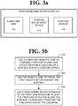
- FIG. 1 illustrates first and second robotic systems 110 and 120 for performing one or more operations on a structure having a confined space.
- the first robotic system 110 includes a positioning and orientation system 112 for moving a first end effector 114 into the confined space and positioning and orienting the first end effector 114 within the confined space.
- the second robotic system 120 includes a positioning and orientation system 122 for moving a second end effector 124 outside the confined space. Once the first and second end effectors 114 and 124 are oriented and positioned, they perform one or more operations (e.g., assembly operations) on the structure.
- operations e.g., assembly operations
- a robotic controller 130 may include a computer that is programmed to operate the robotic systems 110 and 120.
- the computer includes computer memory that is encoded with data for commanding the first and second robotic system 110 and 120.
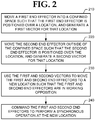
- FIG. 2 illustrates a method of operating the first and second robotic systems 110 and 120 to perform a synchronous operation on a structure having a confined space.
- the structure has a location that is identifiable from within the confined space and also from outside the confined space.
- the location might be identified, without limitation, by visual means (e.g., a mark, a fastener, or a hole or other feature of the structure), magnetic means (e.g., by an embedded magnet), or by an instrumented fastener (described later).
- the first robotic system 110 is commanded to move the first end effector 114 into the confined space such that the first end effector 114 is positioned over the location.
- the first robotic system 110 communicates a first vector to the robotic controller 130.
- the first vector may include position information (e.g., x-y coordinates) and/or angular orientation (e.g., with respect to the surface normal).
- the precision of positioning the first end effector 114 is application-specific. For instance, the precision for aircraft assembly will typically be higher than other types of industrial assembly.
- the second robotic system 120 is commanded to move the second end effector 124 outside of the confined space such that the second end effector 124 is positioned over the location.
- the second robotic system 120 communicates a second vector to the robotic controller 130.
- the second vector may include position information and/or angular orientation.
- the first vector will be used as a frame of reference for the first robotic system 110.
- the second vector will be used as a frame of reference for the second robotic system 120.
- the first and second robotic systems 110 and 120 use the first and second vectors, respectively, to move the first and second end effectors 114 and 124 to a new location.
- the first and second end effectors 114 and 124 are in working opposition, with the first end effector 114 inside the confined space and the second end effector 124 outside the confined space.
- the first and second end effectors 114 and 124 are commanded to perform a synchronous operation at the new location.
- a synchronous assembly operation may be performed at the new location.
- a synchronous operation can be performed on the structure, even though the first end effector 114 isn't visible from outside the confined space. Moreover, the synchronous operation can be performed even though the robotic systems 110 and 120 do not have a single fixed frame of reference.
- the method of Figure 2 can be performed autonomously. Such autonomous operation can reduce or even eliminate manual assembly.
- the method of Figure 2 is not limited to obtaining a reference frame from a single location. If the structure contains multiple locations that are visible from inside and outside the confined space, two or more locations can be used to establish reference frames. An example of using two locations to establish reference frames is described below.
- the apparatus 310 includes a long compliant arm 312 having multiple degrees of freedom.
- One example of such an arm is a snake arm.
- the first end effector is at a free end of the robotic arm 312.
- the apparatus 310 further includes a positioning device 314 attached to the first end effector.
- the compliant arm is used to coarsely position the first end effector over a location of a surface within the confined space.
- the position is coarse due to the compliance of the arm.
- the robotic arm 312 presses the first end effector against the surface. Friction between the first end effector and the surface will prevent the first end effector from shifting its x-y position due to compliance of the arm 312.
- the positioning device 314 is used to shift the position of the first end effector along the surface.
- a vision system 316 or other sensing device may be used to determine when the first end effector is positioned precisely at the location.
- the device 314 can be commanded to repeatedly shift the first end effector until the actual position of the first end effector is within a tolerance of the location.
- the positioning device 314 may be commanded by the robotic controller 130 or by a controller on-board first robotic system 110.
- a synchronous operation and a structure are not limited to anything in particular.
- a fastening operation may be performed on an aircraft structure having a confined space.
- Aircraft structures having at least one confined space include, but are not limited to, wings, horizontal and vertical stabilizers, and cargo compartments and other fuselage compartments.
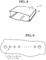
- FIG. 4 illustrates a wing bay 410 of a wing box.
- the wing box includes components such as skin panels 420, spars 430, and ribs (the ribs are not shown).
- Each wing bay 410 has a confined interior space and an access port 440 that leads to the confined space.
- the wing box has a plurality of wing bays 410.
- the methods of Figures 2 and 3b may be adapted to perform permanent fastening operations on a pre-assembled wing box.
- faying i.e., overlapping
- wing box parts e.g., spars, skin panels, and ribs
- sealant eliminates gaps between the faying surfaces to facilitate burrless drilling.
- the pressed-together parts of the wing box may then be fastened (temporarily or permanently) with tack fasteners.
- the tack fasteners may fasten spars to skin panels, spars to ribs, and ribs to skin panels.
- the wing box may be pre-assembled with instrumented fasteners disclosed in assignee's U.S. Serial No. 11/756,447 filed May 31, 2007 .
- an instrumented fastener includes one or more light sources (e.g., light-emitting diodes) configured to produce light beacons. Information regarding the instrumented fastener (e.g., fastener number) may be encoded in the light beacons.
- the instrumented fasteners allow the first robotic system to determine position and an orientation of an axis extending through a fastener location.
- the light beacons are directed inside and outside the wing bay, so they can be sensed by the robotic systems 110 and 120.
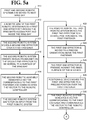
- FIGS. 5a and 5b illustrate a method of performing permanent fastening operations on a pre-assembled wing box of an aircraft.
- the fastening operations will include drilling burrless holes through the wing box, inserting fasteners through the holes such that the fasteners extend into the wing box, and fastening nuts to the bolts from within the wing box.
- the first and second robotic systems are moved to a first wing bay.
- a robotic arm of the first robotic system moves a first end effector through the wing bay's access port and inside the wing bay.
- the second robotic system moves a second end effector outside the wing box until the second end effector is over a first fastener.
- the second robotic system can move the second end effector to a coarse position, determine ⁇ X, ⁇ Y offsets (e.g., using a vision system), determine whether the offsets are within a tolerance, and, if not, adjust the position of second end effector until the offsets are within the tolerance.
- the second end effector will have proper in-plane positioning with respect to the first fastener.
- the pre-assembled wing box will typically have several tack fasteners for each wing bay. One of those fasteners will be identified as the "first."
- the robotic controller could be programmed so the first end effector is moved to a specific location, presumably where the first fastener is roughly located.
- a vision system is used to locate the first fastener.
- the wing box is temporarily assembled with instrumented fasteners whose beacons are encoded with the fastener number. By decoding the beacons, it can be determined whether the end effector is positioned over the "number one" instrumented fastener.
- the second robotic system orients an electromagnet on the second end effector to be normal to a surface of the wing bay.
- the second robotic system can move the second effector to a coarse rotational orientation, determine ⁇ A, ⁇ B angular offsets from the surface normal, determine whether the offsets are within a tolerance, and, if not, adjust the rotational orientation of the second end effector until the offsets are within the tolerance.
- Orientation relative to the surface normal could be sensed by a tactile or non-tactile sensor.
- a sensor could have four detectors arranged in a circle (e.g., at 0°, 90°, 180° and 270°). Each detector measures intensity of the beacon. The second end effector is moved until all intensity measurements are the same, at which point the second end effector is centered over the first fastener and normal to the surface of the wing bay.
- the second robotic assembly generates the location and orientation [XI, Y1, A1, B1] 2 of the second end effector with respect to the first fastener, and communicates this vector to the robotic controller.
- the second robotic system then waits for an input from the first robotic system.
- the robotic arm of the first robotic system moves the first end effector to a coarse position above the first tack fastener.
- the first robotic system can move the first effector to a coarse position, determine ⁇ X, ⁇ Y offsets (e.g., using a vision system) to the first fastener; determine whether the offsets are within a coarse position tolerance, and, if not, adjust the position of first end effector until the offsets are within the coarse position tolerance.
- the first end effector is moved to a precise orientation above the first tack fastener. For example, the first end effector is moved to a rotational orientation.
- Internal sensors or read encoders are used to determine ⁇ A, ⁇ B, and ⁇ C orientation offsets.
- the orientation offsets are compared to a tolerance, and the orientation is further adjusted until the orientation offsets are within the tolerance.
- the first robotic system presses the first end effector against the inner surface of the wing box. Friction between the surfaces will prevent the first end effector from shifting position (due to the compliance of the robotic arm).
- the positioning device attached to the first end effector moves the first end effector to a precise position over the first tack fastener.
- the first robotic system can determine ⁇ X, ⁇ Y offsets (e.g., using a vision system) to the first tack fastener; determine whether the offsets are within a fine position tolerance, and, if not, commands the device to shift the position of first end effector until the offsets are within the fine position tolerance.
- the first robotic system generates the location and orientation [XI, Y1, A1, B1, C1] 1 of the first end effector with respect to the first tack fastener. This vector is communicated to the robotic controller
- the first and second robotic systems are positioned and oriented precisely over an adjacent (second) fastener, and the vectors [X2, Y2, A2, B2, C2] 1 and [X2, Y2, A2, B2] 2 at the second tack fastener are generated and communicated to the robotic controller.
- the functions at blocks 514-530 may be repeated here, except that they are performed for the second fastener.
- the robotic controller computes permanent fastener locations between the first and second fasteners.
- Figure 6 illustrates permanent fastener locations (represented by crosses) that are in-line and equally spaced apart between the first and second fasteners TF1 and TF2.
- the permanent fastener locations are not so limited.
- the permanent fastener locations could follow a curve between the first and second fasteners TF1 and TF2.
- a fastening operation is performed at each permanent fastener location.
- An example of a fastening operation is illustrated in Figure 7 .
- the method of Figure 5 is not limited to such a fastening operation.
- Other fastening operations include, without limitation, riveting.
- the coordinates at the first fastener are set to the coordinates of the second fastener. That is,
- control is returned to block 510, whereby the first and second robotic assemblies are moved to, and perform permanent fastening operations on, the next wing bay.
- the method continues (block 542) until fastening operations have been performed on each wing bay of the wing box.
- FIG. 7 illustrates an example of a fastening operation that is performed by the first and second robotic systems.
- the fastening operation includes clamping the first and second end effectors against their respective surfaces (block 710). This may be done, for example, by activating an electromagnet on the second end effector to magnetically attract a steel plate on the first end effector (magnetic flux from the electromagnet penetrates the parts being clamped together).
- This clamping force squeezes out sealant and eliminates the gap between faying surfaces of parts. This facilitates burrless drilling, which the second end effector performs at block 720.
- the second end effector may also perform countersinking at block 720.
- the second end effector inserts a fastener through the drilled hole.
- the position of the first end effector relative to the inserted bolt is determined. If the offset is not within tolerances (block 750), the positioning device at the end of the first end effector is used to shift the position and/or change the orientation of the first end effector (block 760). The magnetic clamping force between the first and second end effectors may be relaxed to allow the position adjustment.
- the first end effector terminates the end of the fastener.
- the first end effector installs a sleeve and nut onto the fastener.
- the second robotic system 820 may have the same configuration as, and perform the same functions as the first robotic system 810.
- the first and second robotic systems 810 and 820 may include compliant arms 812 and 822 for moving first and second end effectors 814 and 824 in adjacent bays and perform fastening operations on upper and lower halves R U and R L of a rib or other structure.
- these other embodiments are not limited to wing boxes, and may be applied to synchronous operations performed across other adjacent confined spaces.
- a system herein is not limited to a robotic arm for positioning an end effector in a confined space.
- a crawler could be used instead of a robotic arm to position an end effector in a confined space.
- a method herein is not limited to a fastening operation.
- a method herein could be used to perform other operations on an aircraft. Examples of such operations include, without limitation, sealant application, cleaning, painting and inspection within a confined space.
- a method herein is not limited to synchronous operations on an aircraft.
- a method herein could be applied to synchronous operations on containers, autos, trucks, ships, and other structures having confined spaces.
- a method herein is not limited to manufacture. A method herein could be applied to other stages of aircraft manufacture and service.
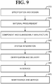
- Figure 9 illustrates for illustrative purposes only an example of an aircraft manufacturing and service method.
- the method may include specification and design 910 of an aircraft and material procurement 920.
- component and subassembly manufacturing 930 and system integration 940 of the aircraft takes place.
- the aircraft may go through certification and delivery 950 in order to be placed in service 960.
- routine maintenance and service 970 which may also include modification, reconfiguration, refurbishment, and so on).
- a system integrator may include without limitation any number of aircraft manufacturers and major-system subcontractors; a third party may include without limitation any number of venders, subcontractors, and suppliers; and an operator may be an airline, leasing company, military entity, service organization, and so on.
- Embodiments herein may be employed during any one or more of the stages of the production and service method.
- components or subassemblies corresponding to production process 930 may be fabricated or manufactured in a manner similar to components or subassemblies produced while the aircraft is in service.
- one or more apparatus embodiments, method embodiments, or a combination thereof may be utilized during the production stages 930 and 940, for example, by substantially expediting assembly of or reducing the cost of an aircraft.
- one or more embodiments herein may be utilized while the aircraft is in service, for example and without limitation, to maintenance and service 970.
Landscapes
- Engineering & Computer Science (AREA)
- Mechanical Engineering (AREA)
- Robotics (AREA)
- Manipulator (AREA)
- Automatic Assembly (AREA)
Claims (12)
- Automatisiertes Verfahren zur Durchführung einer Operation an einer Struktur mit einem engen Raum, wobei die Struktur eine Position aufweist, die von innerhalb des engen Raumes und von außerhalb des engen Raumes identifizierbar ist, wobei das Verfahren aufweist:Verwenden eines ersten Robot-Systems (110), um einen ersten Endeffektor (114) innerhalb des engen Raumes so zu bewegen, dass der erste Endeffektor (114) über der Position positioniert ist, wobei ein nachgiebiger Arm (312) des ersten Robot-Systems (110) verwendet wird, um den ersten Endeffektor grob über der Position zu positionieren und den ersten Endeffektor (114) gegen die Oberfläche zu drücken, und wobei eine Positionierungsvorrichtung (314), die an dem ersten Endeffektor (114) befestigt ist, verwendet wird, um den ersten Endeffektor (114) entlang der Oberfläche zu verschieben, um den ersten Endeffektor genau an der Position zu positionieren und einen ersten Vektor zu erzeugen, der der Position entspricht;Verwenden eines zweiten Robot-Systems (120), um einen zweiten Endeffektor (124) außerhalb des engen Raumes zu bewegen, so dass der zweite End-effektor (124) über der Position positioniert ist, und Erzeugen eines zweiten Vektors entsprechend der Position;Verwenden des ersten und zweiten Vektors, um den ersten und zweiten End-Effektor (114, 124) an eine neue Position zu bewegen, so dass sich der erste und zweite End-Effektor in Arbeitsgegensatz befinden; undVerwenden der ersten und zweiten Endeffektoren (114, 124), um die Operation an der neuen Position durchzuführen.
- Verfahren nach Anspruch 1, wobei jedes Robot-System (110, 120) seinen Vektor an eine Robotersteuerung (130) übermittelt, wenn eine genaue Position erreicht wurde.
- Verfahren nach Anspruch 1 oder 2, wobei der Vorgang einen synchronen Montage umfasst.
- Verfahren nach Anspruch 3, wobei die synchrone Montage aufweist: das zweite Robot-System (120) bohrt ein Loch an der neuen Position und führt ein Befestigungselement durch das Loch ein, und das erste Robot-System terminiert das Befestigungselement.
- Verfahren nach Anspruch 4, ferner umfassend: Erzeugen einer magnetischen Anziehungskraft zwischen dem ersten und dem zweiten Endeffektor.
- Verfahren nach einem der Ansprüche 1 bis 5, ferner umfassend: Verwendung des ersten und zweiten Robot-Systems (110, 120), um den ersten und den zweiten Endeffektor (114, 124) an einer zweiten Position zu positionieren und erste und zweite Vektoren zu erzeugen, die der zweiten Position entsprechen, wobei die neue Position für den ersten Endeffektor (114) in Bezug auf die ersten Vektoren berechnet wird, die den ersten und zweiten Positionen entsprechen, und wobei die neue Position für den zweiten Endeffektor (124) mit den zweiten Vektoren berechnet wird, die der ersten und zweiten Position entsprechen.
- Verfahren nach Anspruch 6, ferner umfassend: Berechnen einer Vielzahl von permanenten Befestigungspositionen zwischen der ersten und der zweiten Position.
- Verfahren nach einem der vorhergehenden Ansprüche, wobei sich ein instrumentiertes Befestigungselement an der Stelle befindet und wobei die Vektoren aus Baken erhalten werden, die durch das instrumentierte Befestigungselement erzeugt werden.
- Verfahren nach einem der vorstehenden Ansprüche, wobei die Struktur ein Flügelkasten eines Flugzeugs ist.
- Verfahren nach Anspruch 9, wobei das zweite Robot-System den zweiten Endeffektor durch eine Zugangsöffnung und in einen engen Raum eines benachbarten Flügelkastens bewegt.
- Gegenstand mit einen Computerspeicher, der mit Daten kodiert ist, um das erste und zweite Robot-System (110, 120) zu steuern, um das Verfahren nach einem der Ansprüche 1 bis 10 durchzuführen.
- System, umfassend ein erstes und ein zweites Robot-System (110, 120); und eine Robotersteuerung (130), um das erste und zweite Robot-System zu veranlassen, das Verfahren nach einem der Ansprüche 1 bis 10 durchzuführen.
Applications Claiming Priority (1)
| Application Number | Priority Date | Filing Date | Title |
|---|---|---|---|
| US12/117,153 US8301302B2 (en) | 2008-05-08 | 2008-05-08 | Synchronous robotic operation on a structure having a confined space |
Publications (3)
| Publication Number | Publication Date |
|---|---|
| EP2116340A1 EP2116340A1 (de) | 2009-11-11 |
| EP2116340B1 true EP2116340B1 (de) | 2019-06-19 |
| EP2116340B8 EP2116340B8 (de) | 2019-08-21 |
Family
ID=40863621
Family Applications (1)
| Application Number | Title | Priority Date | Filing Date |
|---|---|---|---|
| EP09155313.1A Active EP2116340B8 (de) | 2008-05-08 | 2009-03-17 | Synchroner Roboterbetrieb auf einer Struktur mit begrenztem Raum |
Country Status (8)
| Country | Link |
|---|---|
| US (1) | US8301302B2 (de) |
| EP (1) | EP2116340B8 (de) |
| JP (1) | JP5563238B2 (de) |
| KR (1) | KR101644642B1 (de) |
| CN (1) | CN101574805B (de) |
| CA (1) | CA2657085C (de) |
| ES (1) | ES2746178T3 (de) |
| RU (1) | RU2509681C2 (de) |
Families Citing this family (45)
| Publication number | Priority date | Publication date | Assignee | Title |
|---|---|---|---|---|
| US6442451B1 (en) * | 2000-12-28 | 2002-08-27 | Robotic Workspace Technologies, Inc. | Versatile robot control system |
| US20110160905A1 (en) * | 2008-09-03 | 2011-06-30 | Honda Motor Co., Ltd. | Workpiece mounting system, workpiece mounting method, sunroof unit holding device, and sunroof unit holding method |
| US20100217437A1 (en) * | 2009-02-24 | 2010-08-26 | Branko Sarh | Autonomous robotic assembly system |
| US8666546B2 (en) * | 2009-07-10 | 2014-03-04 | The Boeing Company | Autonomous robotic platform |
| US8510952B2 (en) * | 2010-07-15 | 2013-08-20 | The Boeing Company | Agile manufacturing apparatus and method for high throughput |
| US9764464B2 (en) | 2011-08-03 | 2017-09-19 | The Boeing Company | Robot including telescopic assemblies for positioning an end effector |
| JP5469144B2 (ja) * | 2011-09-30 | 2014-04-09 | 富士フイルム株式会社 | 検索画面情報の表示方法、検索画面情報処理システム及びそのプログラム |
| GB2498977B (en) | 2012-02-01 | 2015-10-07 | Bae Systems Plc | Drilling apparatus and method |
| US9517556B2 (en) * | 2012-06-29 | 2016-12-13 | Mitsubishi Electric Corporation | Robot control apparatus and robot control method |
| US8950054B2 (en) | 2012-10-10 | 2015-02-10 | The Boeing Company | Manufacturing method and robotic assembly system |
| US9395041B2 (en) | 2013-05-14 | 2016-07-19 | The Boeing Company | Small frame crawler system |
| US9481028B2 (en) * | 2013-09-26 | 2016-11-01 | The Boeing Company | Automated drilling through pilot holes |
| US9874628B2 (en) * | 2013-11-12 | 2018-01-23 | The Boeing Company | Dual hidden point bars |
| WO2015145407A1 (en) | 2014-03-28 | 2015-10-01 | Composite Cluster Singapore Pte. Ltd. | Freespace composite manufacturing process and device |
| US10046400B2 (en) | 2014-11-18 | 2018-08-14 | Apex Brands, Inc. | System and method of robotic positioning of multiple tools |
| US9975137B2 (en) * | 2015-03-24 | 2018-05-22 | The Boeing Company | Systems and methods for sealant layering |
| US11035672B2 (en) * | 2015-05-12 | 2021-06-15 | The Boeing Company | Sensing of a magnetic target |
| DE202015008713U1 (de) | 2015-12-18 | 2017-03-21 | GM Global Technology Operations LLC (n. d. Ges. d. Staates Delaware) | Roboter mit Werkzeug zur Spurstangenverstellung |
| US9937625B2 (en) * | 2015-12-29 | 2018-04-10 | The Boeing Company | Self-locating robots |
| US10023250B2 (en) * | 2016-06-10 | 2018-07-17 | The Boeing Company | Multi-tread vehicles and methods of operating thereof |
| JP6484213B2 (ja) * | 2016-12-09 | 2019-03-13 | ファナック株式会社 | 複数のロボットを含むロボットシステム、ロボット制御装置、及びロボット制御方法 |
| US10988268B2 (en) * | 2018-06-14 | 2021-04-27 | General Electric Company | System and method for performing operations on an engine |
| EP3670025A1 (de) * | 2018-12-21 | 2020-06-24 | The Boeing Company | Verfahren und vorrichtung zum einseitigen einspannen |
| US11305390B2 (en) | 2018-12-21 | 2022-04-19 | The Boeing Company | Method and apparatus for single-sided clamp-up |
| NL2022545B1 (en) * | 2019-02-08 | 2020-08-19 | Boeing Co | Method and apparatus for single-sided clamp-up |
| US11224951B2 (en) | 2018-12-21 | 2022-01-18 | The Boeing Company | Method and apparatus for single-sided clamp-up |
| EP3677361A1 (de) * | 2018-12-21 | 2020-07-08 | The Boeing Company | Verfahren und vorrichtung zum einseitigen einspannen |
| EP3674012A1 (de) * | 2018-12-21 | 2020-07-01 | The Boeing Company | Hochdichtes robotersystem |
| EP3674011A1 (de) * | 2018-12-21 | 2020-07-01 | The Boeing Company | Hochdichtes robotersystem |
| EP3670024A1 (de) * | 2018-12-21 | 2020-06-24 | The Boeing Company | Verfahren und vorrichtung zum einseitigen einspannen |
| NL2022542B1 (en) * | 2019-02-08 | 2020-08-19 | Boeing Co | Method and apparatus for single-sided clamp-up |
| EP3670021A1 (de) * | 2018-12-21 | 2020-06-24 | The Boeing Company | Verfahren und vorrichtung zum einseitigen einspannen |
| EP3670023A1 (de) * | 2018-12-21 | 2020-06-24 | The Boeing Company | Verfahren und vorrichtung zum einseitigen einspannen |
| US11584503B2 (en) | 2018-12-21 | 2023-02-21 | The Boeing Company | High-density robotic system |
| NL2022546B1 (en) * | 2019-02-08 | 2020-08-19 | Boeing Co | Method and apparatus for single-sided clamp-up |
| NL2022543B1 (en) * | 2019-02-08 | 2020-08-19 | Boeing Co | Method and apparatus for single-sided clamp-up |
| EP3670026A1 (de) * | 2018-12-21 | 2020-06-24 | The Boeing Company | Hochdichtes robotersystem |
| US11224950B2 (en) * | 2018-12-21 | 2022-01-18 | The Boeing Company | Method and apparatus for single-sided clamp-up |
| NL2022540B1 (en) * | 2019-02-08 | 2020-08-19 | Boeing Co | High-density robotic system |
| NL2022547B1 (en) * | 2019-02-08 | 2020-08-19 | Boeing Co | High-density robotic system |
| NL2022541B1 (en) * | 2019-02-08 | 2020-08-19 | Boeing Co | High-density robotic system |
| US11884377B2 (en) | 2018-12-21 | 2024-01-30 | The Boeing Company | High-density robotic system |
| US11110606B2 (en) * | 2019-01-02 | 2021-09-07 | The Boeing Company | Coordinating work within a multi-robot cell |
| US11530621B2 (en) | 2019-10-16 | 2022-12-20 | General Electric Company | Systems and method for use in servicing a machine |
| ES3057139T3 (en) * | 2022-12-19 | 2026-02-26 | Airbus Operations Gmbh | Method and mounting system for mounting a profiled component on an aircraft structural component |
Family Cites Families (26)
| Publication number | Priority date | Publication date | Assignee | Title |
|---|---|---|---|---|
| SU1096094A1 (ru) * | 1983-01-13 | 1984-06-07 | Казанский Ордена Трудового Красного Знамени И Ордена Дружбы Народов Авиационный Институт Им.А.Н.Туполева | Манипул тор с ручным управлением |
| KR950005415B1 (ko) * | 1986-09-19 | 1995-05-24 | 텍사스 인스트루먼츠 인코포레이티드 | 자동 로롯 장치 |
| US4885836A (en) | 1988-04-19 | 1989-12-12 | Imta | Riveting process and apparatus |
| JP2759324B2 (ja) | 1988-04-23 | 1998-05-28 | ファナック株式会社 | ロボットのミラーイメージ方法 |
| FR2647696B1 (fr) | 1989-06-06 | 1991-09-27 | Dassault Avions | Ensemble d'outillage pour rivetage de pieces |
| JP2686839B2 (ja) * | 1990-02-28 | 1997-12-08 | 松下電器産業株式会社 | 産業用ロボットシステム |
| US4995148A (en) * | 1990-03-30 | 1991-02-26 | Imta | Robotically controlled multi-task end effector |
| US5477597A (en) | 1993-04-14 | 1995-12-26 | Gemcor Engineering Corp. | Apparatus for positioning tooling |
| FR2739794B1 (fr) * | 1995-10-11 | 1997-12-26 | Dassault Aviat | Appareillage de rivetage operant par chocs et procede de mise en oeuvre de cet appareillage |
| US6314630B1 (en) * | 1996-03-22 | 2001-11-13 | The Boeing Company | Determinant wing assembly |
| US5785571A (en) * | 1996-09-16 | 1998-07-28 | Camp; Richard S. | Multi-configuration amusement device |
| SE511704C2 (sv) * | 1998-03-19 | 1999-11-08 | Saab Ab | Förfarande och anordning för montering av vinge |
| US6505393B2 (en) * | 1998-07-31 | 2003-01-14 | Airbus Deutschland Gmbh | Two-part riveting apparatus and method for riveting barrel-shaped components such as aircraft fuselage components |
| US6357101B1 (en) | 2000-03-09 | 2002-03-19 | The Boeing Company | Method for installing fasteners in a workpiece |
| US6729809B2 (en) * | 2001-10-09 | 2004-05-04 | The Boeing Company | Combined clamp and drill guide for elimination of inter-laminate burrs during drilling |
| JP3961323B2 (ja) * | 2002-03-28 | 2007-08-22 | 株式会社神戸製鋼所 | ロボットの制御方法、制御ユニット及び制御装置 |
| US6772508B2 (en) * | 2002-07-24 | 2004-08-10 | The Boeing Company | Fastener delivery and installation system |
| CN1256224C (zh) * | 2003-06-26 | 2006-05-17 | 上海交通大学 | 开放式网络机器人通用控制系统 |
| FR2861326B3 (fr) * | 2003-10-24 | 2006-02-03 | Dufieux Ind | Procede et dispositif d'usinage de panneaux |
| FR2865952B1 (fr) * | 2004-02-10 | 2006-06-23 | Airbus France | Procede et dispositif d'usinage mecanique de panneaux flexibles en particulier de forme complexe |
| DE102004015978A1 (de) * | 2004-04-01 | 2005-12-01 | Aksys Gmbh | Verfahren und Einrichtungen zum Aufbringen von Folien auf Innenwandabschnitte einer Fahrzeugkarosserie |
| US7216436B2 (en) * | 2004-08-24 | 2007-05-15 | Bell Helicopter Textron Inc. | Method and apparatus for locating and aligning fasteners |
| US20080028880A1 (en) * | 2006-08-01 | 2008-02-07 | Asada H Harry | Gravity driven underactuated robot arm for assembly operations inside an aircraft wing box |
| US8051547B2 (en) * | 2006-12-29 | 2011-11-08 | The Boeing Company | Robot-deployed assembly tool |
| US7937817B2 (en) * | 2007-05-31 | 2011-05-10 | The Boeing Company | Methods and apparatus for an instrumented fastener |
| US7967549B2 (en) * | 2008-05-15 | 2011-06-28 | The Boeing Company | Robotic system including foldable robotic arm |
-
2008
- 2008-05-08 US US12/117,153 patent/US8301302B2/en active Active
-
2009
- 2009-03-05 CA CA2657085A patent/CA2657085C/en active Active
- 2009-03-17 ES ES09155313T patent/ES2746178T3/es active Active
- 2009-03-17 EP EP09155313.1A patent/EP2116340B8/de active Active
- 2009-04-30 KR KR1020090038338A patent/KR101644642B1/ko active Active
- 2009-05-06 CN CN200910137883.XA patent/CN101574805B/zh active Active
- 2009-05-07 RU RU2009117381/11A patent/RU2509681C2/ru active
- 2009-05-08 JP JP2009113369A patent/JP5563238B2/ja active Active
Non-Patent Citations (1)
| Title |
|---|
| None * |
Also Published As
| Publication number | Publication date |
|---|---|
| CN101574805B (zh) | 2015-03-25 |
| RU2009117381A (ru) | 2010-11-20 |
| JP5563238B2 (ja) | 2014-07-30 |
| US20110245971A1 (en) | 2011-10-06 |
| CA2657085A1 (en) | 2009-11-08 |
| JP2009269168A (ja) | 2009-11-19 |
| CA2657085C (en) | 2015-12-22 |
| EP2116340B8 (de) | 2019-08-21 |
| CN101574805A (zh) | 2009-11-11 |
| EP2116340A1 (de) | 2009-11-11 |
| ES2746178T3 (es) | 2020-03-05 |
| KR101644642B1 (ko) | 2016-08-01 |
| KR20090117622A (ko) | 2009-11-12 |
| US8301302B2 (en) | 2012-10-30 |
| RU2509681C2 (ru) | 2014-03-20 |
Similar Documents
| Publication | Publication Date | Title |
|---|---|---|
| EP2116340B1 (de) | Synchroner Roboterbetrieb auf einer Struktur mit begrenztem Raum | |
| Frommknecht et al. | Multi-sensor measurement system for robotic drilling | |
| JP6602546B2 (ja) | 組立製造のためのシステム及び方法 | |
| Drouot et al. | Measurement assisted assembly for high accuracy aerospace manufacturing | |
| EP2965835B1 (de) | Metrologiebasiertes System zum Betreiben eines flexiblen Fertigungssystems | |
| US10197987B2 (en) | Use of manufacturing compounds to create fiducial marks | |
| EP3028826B1 (de) | Verfahren und vorrichtung für mehrstufige holmanordnung | |
| US20180354654A1 (en) | Apparatus, System, and Method for Supporting a Wing Assembly | |
| US20190210217A1 (en) | Machining station, workpiece holding system, and method of machining a workpiece | |
| EP3560624B1 (de) | Installationssystem und -methode für versetzte befestigungselemente | |
| CA2775480A1 (en) | Manufacturing control system | |
| Liu et al. | Hybrid visual servoing for rivet-in-hole insertion based on super-twisting sliding mode control | |
| Marino et al. | A general low-cost and flexible architecture for robotized drilling in aircraft assembly lines | |
| Mbarek | Positioning system for the aircraft structural assembly | |
| Drouot et al. | Towards industry 4.0: the future automated aircraft assembly demonstrator | |
| Bastidas-Cruz et al. | Implementing human-robot collaboration in highly dynamic environments: Assessment, planning and development | |
| Richardson et al. | Evolution of Mobile Robotic Manufacturing Systems at Spirit AeroSystems | |
| Liu et al. | Riveting for Helicopter Assembly | |
| Le Vacon et al. | Numerical Template | |
| Eastwood et al. | Simulation at the Heart of an Automated Aerospace Manufacturing Process | |
| Zhao et al. | Towards Industry 4.0: The Future Automated Aircraft Assembly Demonstrator |
Legal Events
| Date | Code | Title | Description |
|---|---|---|---|
| PUAI | Public reference made under article 153(3) epc to a published international application that has entered the european phase |
Free format text: ORIGINAL CODE: 0009012 |
|
| AK | Designated contracting states |
Kind code of ref document: A1 Designated state(s): AT BE BG CH CY CZ DE DK EE ES FI FR GB GR HR HU IE IS IT LI LT LU LV MC MK MT NL NO PL PT RO SE SI SK TR |
|
| AX | Request for extension of the european patent |
Extension state: AL BA RS |
|
| 17P | Request for examination filed |
Effective date: 20100422 |
|
| AKX | Designation fees paid |
Designated state(s): AT BE BG CH CY CZ DE DK EE ES FI FR GB GR HR HU IE IS IT LI LT LU LV MC MK MT NL NO PL PT RO SE SI SK TR |
|
| 17Q | First examination report despatched |
Effective date: 20100623 |
|
| STAA | Information on the status of an ep patent application or granted ep patent |
Free format text: STATUS: EXAMINATION IS IN PROGRESS |
|
| GRAP | Despatch of communication of intention to grant a patent |
Free format text: ORIGINAL CODE: EPIDOSNIGR1 |
|
| STAA | Information on the status of an ep patent application or granted ep patent |
Free format text: STATUS: GRANT OF PATENT IS INTENDED |
|
| INTG | Intention to grant announced |
Effective date: 20190103 |
|
| GRAS | Grant fee paid |
Free format text: ORIGINAL CODE: EPIDOSNIGR3 |
|
| GRAA | (expected) grant |
Free format text: ORIGINAL CODE: 0009210 |
|
| STAA | Information on the status of an ep patent application or granted ep patent |
Free format text: STATUS: THE PATENT HAS BEEN GRANTED |
|
| AK | Designated contracting states |
Kind code of ref document: B1 Designated state(s): AT BE BG CH CY CZ DE DK EE ES FI FR GB GR HR HU IE IS IT LI LT LU LV MC MK MT NL NO PL PT RO SE SI SK TR |
|
| REG | Reference to a national code |
Ref country code: GB Ref legal event code: FG4D |
|
| REG | Reference to a national code |
Ref country code: CH Ref legal event code: EP |
|
| REG | Reference to a national code |
Ref country code: IE Ref legal event code: FG4D |
|
| REG | Reference to a national code |
Ref country code: AT Ref legal event code: REF Ref document number: 1144885 Country of ref document: AT Kind code of ref document: T Effective date: 20190715 |
|
| REG | Reference to a national code |
Ref country code: DE Ref legal event code: R096 Ref document number: 602009058766 Country of ref document: DE |
|
| REG | Reference to a national code |
Ref country code: CH Ref legal event code: PK Free format text: BERICHTIGUNG B8 |
|
| REG | Reference to a national code |
Ref country code: NL Ref legal event code: MP Effective date: 20190619 |
|
| PG25 | Lapsed in a contracting state [announced via postgrant information from national office to epo] |
Ref country code: SE Free format text: LAPSE BECAUSE OF FAILURE TO SUBMIT A TRANSLATION OF THE DESCRIPTION OR TO PAY THE FEE WITHIN THE PRESCRIBED TIME-LIMIT Effective date: 20190619 Ref country code: LT Free format text: LAPSE BECAUSE OF FAILURE TO SUBMIT A TRANSLATION OF THE DESCRIPTION OR TO PAY THE FEE WITHIN THE PRESCRIBED TIME-LIMIT Effective date: 20190619 Ref country code: HR Free format text: LAPSE BECAUSE OF FAILURE TO SUBMIT A TRANSLATION OF THE DESCRIPTION OR TO PAY THE FEE WITHIN THE PRESCRIBED TIME-LIMIT Effective date: 20190619 Ref country code: NO Free format text: LAPSE BECAUSE OF FAILURE TO SUBMIT A TRANSLATION OF THE DESCRIPTION OR TO PAY THE FEE WITHIN THE PRESCRIBED TIME-LIMIT Effective date: 20190919 Ref country code: FI Free format text: LAPSE BECAUSE OF FAILURE TO SUBMIT A TRANSLATION OF THE DESCRIPTION OR TO PAY THE FEE WITHIN THE PRESCRIBED TIME-LIMIT Effective date: 20190619 |
|
| REG | Reference to a national code |
Ref country code: LT Ref legal event code: MG4D |
|
| PG25 | Lapsed in a contracting state [announced via postgrant information from national office to epo] |
Ref country code: BG Free format text: LAPSE BECAUSE OF FAILURE TO SUBMIT A TRANSLATION OF THE DESCRIPTION OR TO PAY THE FEE WITHIN THE PRESCRIBED TIME-LIMIT Effective date: 20190919 Ref country code: LV Free format text: LAPSE BECAUSE OF FAILURE TO SUBMIT A TRANSLATION OF THE DESCRIPTION OR TO PAY THE FEE WITHIN THE PRESCRIBED TIME-LIMIT Effective date: 20190619 Ref country code: GR Free format text: LAPSE BECAUSE OF FAILURE TO SUBMIT A TRANSLATION OF THE DESCRIPTION OR TO PAY THE FEE WITHIN THE PRESCRIBED TIME-LIMIT Effective date: 20190920 |
|
| REG | Reference to a national code |
Ref country code: AT Ref legal event code: MK05 Ref document number: 1144885 Country of ref document: AT Kind code of ref document: T Effective date: 20190619 |
|
| PG25 | Lapsed in a contracting state [announced via postgrant information from national office to epo] |
Ref country code: NL Free format text: LAPSE BECAUSE OF FAILURE TO SUBMIT A TRANSLATION OF THE DESCRIPTION OR TO PAY THE FEE WITHIN THE PRESCRIBED TIME-LIMIT Effective date: 20190619 Ref country code: EE Free format text: LAPSE BECAUSE OF FAILURE TO SUBMIT A TRANSLATION OF THE DESCRIPTION OR TO PAY THE FEE WITHIN THE PRESCRIBED TIME-LIMIT Effective date: 20190619 Ref country code: AT Free format text: LAPSE BECAUSE OF FAILURE TO SUBMIT A TRANSLATION OF THE DESCRIPTION OR TO PAY THE FEE WITHIN THE PRESCRIBED TIME-LIMIT Effective date: 20190619 Ref country code: PT Free format text: LAPSE BECAUSE OF FAILURE TO SUBMIT A TRANSLATION OF THE DESCRIPTION OR TO PAY THE FEE WITHIN THE PRESCRIBED TIME-LIMIT Effective date: 20191021 Ref country code: SK Free format text: LAPSE BECAUSE OF FAILURE TO SUBMIT A TRANSLATION OF THE DESCRIPTION OR TO PAY THE FEE WITHIN THE PRESCRIBED TIME-LIMIT Effective date: 20190619 Ref country code: CZ Free format text: LAPSE BECAUSE OF FAILURE TO SUBMIT A TRANSLATION OF THE DESCRIPTION OR TO PAY THE FEE WITHIN THE PRESCRIBED TIME-LIMIT Effective date: 20190619 Ref country code: RO Free format text: LAPSE BECAUSE OF FAILURE TO SUBMIT A TRANSLATION OF THE DESCRIPTION OR TO PAY THE FEE WITHIN THE PRESCRIBED TIME-LIMIT Effective date: 20190619 |
|
| PG25 | Lapsed in a contracting state [announced via postgrant information from national office to epo] |
Ref country code: IS Free format text: LAPSE BECAUSE OF FAILURE TO SUBMIT A TRANSLATION OF THE DESCRIPTION OR TO PAY THE FEE WITHIN THE PRESCRIBED TIME-LIMIT Effective date: 20191019 |
|
| REG | Reference to a national code |
Ref country code: ES Ref legal event code: FG2A Ref document number: 2746178 Country of ref document: ES Kind code of ref document: T3 Effective date: 20200305 |
|
| PG25 | Lapsed in a contracting state [announced via postgrant information from national office to epo] |
Ref country code: TR Free format text: LAPSE BECAUSE OF FAILURE TO SUBMIT A TRANSLATION OF THE DESCRIPTION OR TO PAY THE FEE WITHIN THE PRESCRIBED TIME-LIMIT Effective date: 20190619 |
|
| PG25 | Lapsed in a contracting state [announced via postgrant information from national office to epo] |
Ref country code: PL Free format text: LAPSE BECAUSE OF FAILURE TO SUBMIT A TRANSLATION OF THE DESCRIPTION OR TO PAY THE FEE WITHIN THE PRESCRIBED TIME-LIMIT Effective date: 20190619 Ref country code: DK Free format text: LAPSE BECAUSE OF FAILURE TO SUBMIT A TRANSLATION OF THE DESCRIPTION OR TO PAY THE FEE WITHIN THE PRESCRIBED TIME-LIMIT Effective date: 20190619 |
|
| PG25 | Lapsed in a contracting state [announced via postgrant information from national office to epo] |
Ref country code: IS Free format text: LAPSE BECAUSE OF FAILURE TO SUBMIT A TRANSLATION OF THE DESCRIPTION OR TO PAY THE FEE WITHIN THE PRESCRIBED TIME-LIMIT Effective date: 20200224 |
|
| REG | Reference to a national code |
Ref country code: DE Ref legal event code: R097 Ref document number: 602009058766 Country of ref document: DE |
|
| PLBE | No opposition filed within time limit |
Free format text: ORIGINAL CODE: 0009261 |
|
| STAA | Information on the status of an ep patent application or granted ep patent |
Free format text: STATUS: NO OPPOSITION FILED WITHIN TIME LIMIT |
|
| PG2D | Information on lapse in contracting state deleted |
Ref country code: IS |
|
| 26N | No opposition filed |
Effective date: 20200603 |
|
| PG25 | Lapsed in a contracting state [announced via postgrant information from national office to epo] |
Ref country code: SI Free format text: LAPSE BECAUSE OF FAILURE TO SUBMIT A TRANSLATION OF THE DESCRIPTION OR TO PAY THE FEE WITHIN THE PRESCRIBED TIME-LIMIT Effective date: 20190619 |
|
| PG25 | Lapsed in a contracting state [announced via postgrant information from national office to epo] |
Ref country code: MC Free format text: LAPSE BECAUSE OF FAILURE TO SUBMIT A TRANSLATION OF THE DESCRIPTION OR TO PAY THE FEE WITHIN THE PRESCRIBED TIME-LIMIT Effective date: 20190619 |
|
| REG | Reference to a national code |
Ref country code: CH Ref legal event code: PL |
|
| REG | Reference to a national code |
Ref country code: BE Ref legal event code: MM Effective date: 20200331 |
|
| PG25 | Lapsed in a contracting state [announced via postgrant information from national office to epo] |
Ref country code: LU Free format text: LAPSE BECAUSE OF NON-PAYMENT OF DUE FEES Effective date: 20200317 |
|
| PG25 | Lapsed in a contracting state [announced via postgrant information from national office to epo] |
Ref country code: IE Free format text: LAPSE BECAUSE OF NON-PAYMENT OF DUE FEES Effective date: 20200317 Ref country code: CH Free format text: LAPSE BECAUSE OF NON-PAYMENT OF DUE FEES Effective date: 20200331 Ref country code: LI Free format text: LAPSE BECAUSE OF NON-PAYMENT OF DUE FEES Effective date: 20200331 |
|
| PG25 | Lapsed in a contracting state [announced via postgrant information from national office to epo] |
Ref country code: BE Free format text: LAPSE BECAUSE OF NON-PAYMENT OF DUE FEES Effective date: 20200331 |
|
| PG25 | Lapsed in a contracting state [announced via postgrant information from national office to epo] |
Ref country code: MT Free format text: LAPSE BECAUSE OF FAILURE TO SUBMIT A TRANSLATION OF THE DESCRIPTION OR TO PAY THE FEE WITHIN THE PRESCRIBED TIME-LIMIT Effective date: 20190619 Ref country code: CY Free format text: LAPSE BECAUSE OF FAILURE TO SUBMIT A TRANSLATION OF THE DESCRIPTION OR TO PAY THE FEE WITHIN THE PRESCRIBED TIME-LIMIT Effective date: 20190619 |
|
| PG25 | Lapsed in a contracting state [announced via postgrant information from national office to epo] |
Ref country code: MK Free format text: LAPSE BECAUSE OF FAILURE TO SUBMIT A TRANSLATION OF THE DESCRIPTION OR TO PAY THE FEE WITHIN THE PRESCRIBED TIME-LIMIT Effective date: 20190619 |
|
| P01 | Opt-out of the competence of the unified patent court (upc) registered |
Effective date: 20230516 |
|
| PGFP | Annual fee paid to national office [announced via postgrant information from national office to epo] |
Ref country code: ES Payment date: 20250401 Year of fee payment: 17 |
|
| PGFP | Annual fee paid to national office [announced via postgrant information from national office to epo] |
Ref country code: GB Payment date: 20260327 Year of fee payment: 18 |
|
| PGFP | Annual fee paid to national office [announced via postgrant information from national office to epo] |
Ref country code: DE Payment date: 20260327 Year of fee payment: 18 |
|
| PGFP | Annual fee paid to national office [announced via postgrant information from national office to epo] |
Ref country code: IT Payment date: 20260319 Year of fee payment: 18 |
|
| PGFP | Annual fee paid to national office [announced via postgrant information from national office to epo] |
Ref country code: FR Payment date: 20260325 Year of fee payment: 18 |