EP2116412A2 - Vorrichtung zum Elektroantrieb oder -betrieb eines Fahrzeugs - Google Patents
Vorrichtung zum Elektroantrieb oder -betrieb eines Fahrzeugs Download PDFInfo
- Publication number
- EP2116412A2 EP2116412A2 EP20090305398 EP09305398A EP2116412A2 EP 2116412 A2 EP2116412 A2 EP 2116412A2 EP 20090305398 EP20090305398 EP 20090305398 EP 09305398 A EP09305398 A EP 09305398A EP 2116412 A2 EP2116412 A2 EP 2116412A2
- Authority
- EP
- European Patent Office
- Prior art keywords
- motor
- vehicle
- wheels
- electric motor
- coupling means
- Prior art date
- Legal status (The legal status is an assumption and is not a legal conclusion. Google has not performed a legal analysis and makes no representation as to the accuracy of the status listed.)
- Withdrawn
Links
- 230000008878 coupling Effects 0.000 claims abstract description 36
- 238000010168 coupling process Methods 0.000 claims abstract description 36
- 238000005859 coupling reaction Methods 0.000 claims abstract description 36
- 238000000034 method Methods 0.000 claims description 11
- 230000009467 reduction Effects 0.000 claims description 7
- 210000000078 claw Anatomy 0.000 claims description 2
- 230000005540 biological transmission Effects 0.000 description 12
- 238000011084 recovery Methods 0.000 description 10
- 230000008901 benefit Effects 0.000 description 8
- 230000001133 acceleration Effects 0.000 description 6
- 230000001276 controlling effect Effects 0.000 description 6
- 240000008042 Zea mays Species 0.000 description 5
- 230000008859 change Effects 0.000 description 5
- 238000001514 detection method Methods 0.000 description 3
- 230000001172 regenerating effect Effects 0.000 description 3
- 238000005516 engineering process Methods 0.000 description 2
- 235000021183 entrée Nutrition 0.000 description 2
- 230000001105 regulatory effect Effects 0.000 description 2
- 230000007704 transition Effects 0.000 description 2
- 229920000297 Rayon Polymers 0.000 description 1
- 238000004364 calculation method Methods 0.000 description 1
- 230000036461 convulsion Effects 0.000 description 1
- 238000001816 cooling Methods 0.000 description 1
- 230000003247 decreasing effect Effects 0.000 description 1
- 238000011161 development Methods 0.000 description 1
- 238000006073 displacement reaction Methods 0.000 description 1
- 230000009977 dual effect Effects 0.000 description 1
- 230000007613 environmental effect Effects 0.000 description 1
- 230000005484 gravity Effects 0.000 description 1
- 238000010438 heat treatment Methods 0.000 description 1
- 230000006872 improvement Effects 0.000 description 1
- 238000003780 insertion Methods 0.000 description 1
- 230000037431 insertion Effects 0.000 description 1
- 238000012423 maintenance Methods 0.000 description 1
- 210000000056 organ Anatomy 0.000 description 1
- 238000003825 pressing Methods 0.000 description 1
- 239000002964 rayon Substances 0.000 description 1
- 230000008439 repair process Effects 0.000 description 1
- 230000002459 sustained effect Effects 0.000 description 1
- 238000013519 translation Methods 0.000 description 1
Images



Classifications
-
- B—PERFORMING OPERATIONS; TRANSPORTING
- B60—VEHICLES IN GENERAL
- B60K—ARRANGEMENT OR MOUNTING OF PROPULSION UNITS OR OF TRANSMISSIONS IN VEHICLES; ARRANGEMENT OR MOUNTING OF PLURAL DIVERSE PRIME-MOVERS IN VEHICLES; AUXILIARY DRIVES FOR VEHICLES; INSTRUMENTATION OR DASHBOARDS FOR VEHICLES; ARRANGEMENTS IN CONNECTION WITH COOLING, AIR INTAKE, GAS EXHAUST OR FUEL SUPPLY OF PROPULSION UNITS IN VEHICLES
- B60K1/00—Arrangement or mounting of electrical propulsion units
- B60K1/02—Arrangement or mounting of electrical propulsion units comprising more than one electric motor
-
- B—PERFORMING OPERATIONS; TRANSPORTING
- B60—VEHICLES IN GENERAL
- B60L—PROPULSION OF ELECTRICALLY-PROPELLED VEHICLES; SUPPLYING ELECTRIC POWER FOR AUXILIARY EQUIPMENT OF ELECTRICALLY-PROPELLED VEHICLES; ELECTRODYNAMIC BRAKE SYSTEMS FOR VEHICLES IN GENERAL; MAGNETIC SUSPENSION OR LEVITATION FOR VEHICLES; MONITORING OPERATING VARIABLES OF ELECTRICALLY-PROPELLED VEHICLES; ELECTRIC SAFETY DEVICES FOR ELECTRICALLY-PROPELLED VEHICLES
- B60L15/00—Methods, circuits, or devices for controlling the traction-motor speed of electrically-propelled vehicles
- B60L15/20—Methods, circuits, or devices for controlling the traction-motor speed of electrically-propelled vehicles for control of the vehicle or its driving motor to achieve a desired performance, e.g. speed, torque, programmed variation of speed
- B60L15/2009—Methods, circuits, or devices for controlling the traction-motor speed of electrically-propelled vehicles for control of the vehicle or its driving motor to achieve a desired performance, e.g. speed, torque, programmed variation of speed for braking
-
- B—PERFORMING OPERATIONS; TRANSPORTING
- B60—VEHICLES IN GENERAL
- B60L—PROPULSION OF ELECTRICALLY-PROPELLED VEHICLES; SUPPLYING ELECTRIC POWER FOR AUXILIARY EQUIPMENT OF ELECTRICALLY-PROPELLED VEHICLES; ELECTRODYNAMIC BRAKE SYSTEMS FOR VEHICLES IN GENERAL; MAGNETIC SUSPENSION OR LEVITATION FOR VEHICLES; MONITORING OPERATING VARIABLES OF ELECTRICALLY-PROPELLED VEHICLES; ELECTRIC SAFETY DEVICES FOR ELECTRICALLY-PROPELLED VEHICLES
- B60L15/00—Methods, circuits, or devices for controlling the traction-motor speed of electrically-propelled vehicles
- B60L15/20—Methods, circuits, or devices for controlling the traction-motor speed of electrically-propelled vehicles for control of the vehicle or its driving motor to achieve a desired performance, e.g. speed, torque, programmed variation of speed
- B60L15/2045—Methods, circuits, or devices for controlling the traction-motor speed of electrically-propelled vehicles for control of the vehicle or its driving motor to achieve a desired performance, e.g. speed, torque, programmed variation of speed for optimising the use of energy
-
- B—PERFORMING OPERATIONS; TRANSPORTING
- B60—VEHICLES IN GENERAL
- B60L—PROPULSION OF ELECTRICALLY-PROPELLED VEHICLES; SUPPLYING ELECTRIC POWER FOR AUXILIARY EQUIPMENT OF ELECTRICALLY-PROPELLED VEHICLES; ELECTRODYNAMIC BRAKE SYSTEMS FOR VEHICLES IN GENERAL; MAGNETIC SUSPENSION OR LEVITATION FOR VEHICLES; MONITORING OPERATING VARIABLES OF ELECTRICALLY-PROPELLED VEHICLES; ELECTRIC SAFETY DEVICES FOR ELECTRICALLY-PROPELLED VEHICLES
- B60L15/00—Methods, circuits, or devices for controlling the traction-motor speed of electrically-propelled vehicles
- B60L15/20—Methods, circuits, or devices for controlling the traction-motor speed of electrically-propelled vehicles for control of the vehicle or its driving motor to achieve a desired performance, e.g. speed, torque, programmed variation of speed
- B60L15/2054—Methods, circuits, or devices for controlling the traction-motor speed of electrically-propelled vehicles for control of the vehicle or its driving motor to achieve a desired performance, e.g. speed, torque, programmed variation of speed by controlling transmissions or clutches
-
- B—PERFORMING OPERATIONS; TRANSPORTING
- B60—VEHICLES IN GENERAL
- B60L—PROPULSION OF ELECTRICALLY-PROPELLED VEHICLES; SUPPLYING ELECTRIC POWER FOR AUXILIARY EQUIPMENT OF ELECTRICALLY-PROPELLED VEHICLES; ELECTRODYNAMIC BRAKE SYSTEMS FOR VEHICLES IN GENERAL; MAGNETIC SUSPENSION OR LEVITATION FOR VEHICLES; MONITORING OPERATING VARIABLES OF ELECTRICALLY-PROPELLED VEHICLES; ELECTRIC SAFETY DEVICES FOR ELECTRICALLY-PROPELLED VEHICLES
- B60L3/00—Electric devices on electrically-propelled vehicles for safety purposes; Monitoring operating variables, e.g. speed, deceleration or energy consumption
- B60L3/0023—Detecting, eliminating, remedying or compensating for drive train abnormalities, e.g. failures within the drive train
- B60L3/003—Detecting, eliminating, remedying or compensating for drive train abnormalities, e.g. failures within the drive train relating to inverters
-
- B—PERFORMING OPERATIONS; TRANSPORTING
- B60—VEHICLES IN GENERAL
- B60L—PROPULSION OF ELECTRICALLY-PROPELLED VEHICLES; SUPPLYING ELECTRIC POWER FOR AUXILIARY EQUIPMENT OF ELECTRICALLY-PROPELLED VEHICLES; ELECTRODYNAMIC BRAKE SYSTEMS FOR VEHICLES IN GENERAL; MAGNETIC SUSPENSION OR LEVITATION FOR VEHICLES; MONITORING OPERATING VARIABLES OF ELECTRICALLY-PROPELLED VEHICLES; ELECTRIC SAFETY DEVICES FOR ELECTRICALLY-PROPELLED VEHICLES
- B60L3/00—Electric devices on electrically-propelled vehicles for safety purposes; Monitoring operating variables, e.g. speed, deceleration or energy consumption
- B60L3/0023—Detecting, eliminating, remedying or compensating for drive train abnormalities, e.g. failures within the drive train
- B60L3/0061—Detecting, eliminating, remedying or compensating for drive train abnormalities, e.g. failures within the drive train relating to electrical machines
-
- B—PERFORMING OPERATIONS; TRANSPORTING
- B60—VEHICLES IN GENERAL
- B60L—PROPULSION OF ELECTRICALLY-PROPELLED VEHICLES; SUPPLYING ELECTRIC POWER FOR AUXILIARY EQUIPMENT OF ELECTRICALLY-PROPELLED VEHICLES; ELECTRODYNAMIC BRAKE SYSTEMS FOR VEHICLES IN GENERAL; MAGNETIC SUSPENSION OR LEVITATION FOR VEHICLES; MONITORING OPERATING VARIABLES OF ELECTRICALLY-PROPELLED VEHICLES; ELECTRIC SAFETY DEVICES FOR ELECTRICALLY-PROPELLED VEHICLES
- B60L3/00—Electric devices on electrically-propelled vehicles for safety purposes; Monitoring operating variables, e.g. speed, deceleration or energy consumption
- B60L3/04—Cutting off the power supply under fault conditions
-
- B—PERFORMING OPERATIONS; TRANSPORTING
- B60—VEHICLES IN GENERAL
- B60L—PROPULSION OF ELECTRICALLY-PROPELLED VEHICLES; SUPPLYING ELECTRIC POWER FOR AUXILIARY EQUIPMENT OF ELECTRICALLY-PROPELLED VEHICLES; ELECTRODYNAMIC BRAKE SYSTEMS FOR VEHICLES IN GENERAL; MAGNETIC SUSPENSION OR LEVITATION FOR VEHICLES; MONITORING OPERATING VARIABLES OF ELECTRICALLY-PROPELLED VEHICLES; ELECTRIC SAFETY DEVICES FOR ELECTRICALLY-PROPELLED VEHICLES
- B60L58/00—Methods or circuit arrangements for monitoring or controlling batteries or fuel cells, specially adapted for electric vehicles
- B60L58/10—Methods or circuit arrangements for monitoring or controlling batteries or fuel cells, specially adapted for electric vehicles for monitoring or controlling batteries
- B60L58/12—Methods or circuit arrangements for monitoring or controlling batteries or fuel cells, specially adapted for electric vehicles for monitoring or controlling batteries responding to state of charge [SoC]
-
- B—PERFORMING OPERATIONS; TRANSPORTING
- B60—VEHICLES IN GENERAL
- B60L—PROPULSION OF ELECTRICALLY-PROPELLED VEHICLES; SUPPLYING ELECTRIC POWER FOR AUXILIARY EQUIPMENT OF ELECTRICALLY-PROPELLED VEHICLES; ELECTRODYNAMIC BRAKE SYSTEMS FOR VEHICLES IN GENERAL; MAGNETIC SUSPENSION OR LEVITATION FOR VEHICLES; MONITORING OPERATING VARIABLES OF ELECTRICALLY-PROPELLED VEHICLES; ELECTRIC SAFETY DEVICES FOR ELECTRICALLY-PROPELLED VEHICLES
- B60L7/00—Electrodynamic brake systems for vehicles in general
- B60L7/10—Dynamic electric regenerative braking
- B60L7/12—Dynamic electric regenerative braking for vehicles propelled by DC motors
-
- B—PERFORMING OPERATIONS; TRANSPORTING
- B60—VEHICLES IN GENERAL
- B60K—ARRANGEMENT OR MOUNTING OF PROPULSION UNITS OR OF TRANSMISSIONS IN VEHICLES; ARRANGEMENT OR MOUNTING OF PLURAL DIVERSE PRIME-MOVERS IN VEHICLES; AUXILIARY DRIVES FOR VEHICLES; INSTRUMENTATION OR DASHBOARDS FOR VEHICLES; ARRANGEMENTS IN CONNECTION WITH COOLING, AIR INTAKE, GAS EXHAUST OR FUEL SUPPLY OF PROPULSION UNITS IN VEHICLES
- B60K1/00—Arrangement or mounting of electrical propulsion units
- B60K2001/001—Arrangement or mounting of electrical propulsion units one motor mounted on a propulsion axle for rotating right and left wheels of this axle
-
- B—PERFORMING OPERATIONS; TRANSPORTING
- B60—VEHICLES IN GENERAL
- B60L—PROPULSION OF ELECTRICALLY-PROPELLED VEHICLES; SUPPLYING ELECTRIC POWER FOR AUXILIARY EQUIPMENT OF ELECTRICALLY-PROPELLED VEHICLES; ELECTRODYNAMIC BRAKE SYSTEMS FOR VEHICLES IN GENERAL; MAGNETIC SUSPENSION OR LEVITATION FOR VEHICLES; MONITORING OPERATING VARIABLES OF ELECTRICALLY-PROPELLED VEHICLES; ELECTRIC SAFETY DEVICES FOR ELECTRICALLY-PROPELLED VEHICLES
- B60L2220/00—Electrical machine types; Structures or applications thereof
- B60L2220/40—Electrical machine applications
- B60L2220/42—Electrical machine applications with use of more than one motor
-
- B—PERFORMING OPERATIONS; TRANSPORTING
- B60—VEHICLES IN GENERAL
- B60L—PROPULSION OF ELECTRICALLY-PROPELLED VEHICLES; SUPPLYING ELECTRIC POWER FOR AUXILIARY EQUIPMENT OF ELECTRICALLY-PROPELLED VEHICLES; ELECTRODYNAMIC BRAKE SYSTEMS FOR VEHICLES IN GENERAL; MAGNETIC SUSPENSION OR LEVITATION FOR VEHICLES; MONITORING OPERATING VARIABLES OF ELECTRICALLY-PROPELLED VEHICLES; ELECTRIC SAFETY DEVICES FOR ELECTRICALLY-PROPELLED VEHICLES
- B60L2240/00—Control parameters of input or output; Target parameters
- B60L2240/10—Vehicle control parameters
- B60L2240/12—Speed
-
- B—PERFORMING OPERATIONS; TRANSPORTING
- B60—VEHICLES IN GENERAL
- B60L—PROPULSION OF ELECTRICALLY-PROPELLED VEHICLES; SUPPLYING ELECTRIC POWER FOR AUXILIARY EQUIPMENT OF ELECTRICALLY-PROPELLED VEHICLES; ELECTRODYNAMIC BRAKE SYSTEMS FOR VEHICLES IN GENERAL; MAGNETIC SUSPENSION OR LEVITATION FOR VEHICLES; MONITORING OPERATING VARIABLES OF ELECTRICALLY-PROPELLED VEHICLES; ELECTRIC SAFETY DEVICES FOR ELECTRICALLY-PROPELLED VEHICLES
- B60L2240/00—Control parameters of input or output; Target parameters
- B60L2240/10—Vehicle control parameters
- B60L2240/36—Temperature of vehicle components or parts
-
- B—PERFORMING OPERATIONS; TRANSPORTING
- B60—VEHICLES IN GENERAL
- B60L—PROPULSION OF ELECTRICALLY-PROPELLED VEHICLES; SUPPLYING ELECTRIC POWER FOR AUXILIARY EQUIPMENT OF ELECTRICALLY-PROPELLED VEHICLES; ELECTRODYNAMIC BRAKE SYSTEMS FOR VEHICLES IN GENERAL; MAGNETIC SUSPENSION OR LEVITATION FOR VEHICLES; MONITORING OPERATING VARIABLES OF ELECTRICALLY-PROPELLED VEHICLES; ELECTRIC SAFETY DEVICES FOR ELECTRICALLY-PROPELLED VEHICLES
- B60L2240/00—Control parameters of input or output; Target parameters
- B60L2240/40—Drive Train control parameters
- B60L2240/42—Drive Train control parameters related to electric machines
- B60L2240/421—Speed
-
- B—PERFORMING OPERATIONS; TRANSPORTING
- B60—VEHICLES IN GENERAL
- B60L—PROPULSION OF ELECTRICALLY-PROPELLED VEHICLES; SUPPLYING ELECTRIC POWER FOR AUXILIARY EQUIPMENT OF ELECTRICALLY-PROPELLED VEHICLES; ELECTRODYNAMIC BRAKE SYSTEMS FOR VEHICLES IN GENERAL; MAGNETIC SUSPENSION OR LEVITATION FOR VEHICLES; MONITORING OPERATING VARIABLES OF ELECTRICALLY-PROPELLED VEHICLES; ELECTRIC SAFETY DEVICES FOR ELECTRICALLY-PROPELLED VEHICLES
- B60L2240/00—Control parameters of input or output; Target parameters
- B60L2240/40—Drive Train control parameters
- B60L2240/42—Drive Train control parameters related to electric machines
- B60L2240/423—Torque
-
- B—PERFORMING OPERATIONS; TRANSPORTING
- B60—VEHICLES IN GENERAL
- B60L—PROPULSION OF ELECTRICALLY-PROPELLED VEHICLES; SUPPLYING ELECTRIC POWER FOR AUXILIARY EQUIPMENT OF ELECTRICALLY-PROPELLED VEHICLES; ELECTRODYNAMIC BRAKE SYSTEMS FOR VEHICLES IN GENERAL; MAGNETIC SUSPENSION OR LEVITATION FOR VEHICLES; MONITORING OPERATING VARIABLES OF ELECTRICALLY-PROPELLED VEHICLES; ELECTRIC SAFETY DEVICES FOR ELECTRICALLY-PROPELLED VEHICLES
- B60L2240/00—Control parameters of input or output; Target parameters
- B60L2240/40—Drive Train control parameters
- B60L2240/54—Drive Train control parameters related to batteries
- B60L2240/545—Temperature
-
- B—PERFORMING OPERATIONS; TRANSPORTING
- B60—VEHICLES IN GENERAL
- B60L—PROPULSION OF ELECTRICALLY-PROPELLED VEHICLES; SUPPLYING ELECTRIC POWER FOR AUXILIARY EQUIPMENT OF ELECTRICALLY-PROPELLED VEHICLES; ELECTRODYNAMIC BRAKE SYSTEMS FOR VEHICLES IN GENERAL; MAGNETIC SUSPENSION OR LEVITATION FOR VEHICLES; MONITORING OPERATING VARIABLES OF ELECTRICALLY-PROPELLED VEHICLES; ELECTRIC SAFETY DEVICES FOR ELECTRICALLY-PROPELLED VEHICLES
- B60L2240/00—Control parameters of input or output; Target parameters
- B60L2240/80—Time limits
-
- B—PERFORMING OPERATIONS; TRANSPORTING
- B60—VEHICLES IN GENERAL
- B60L—PROPULSION OF ELECTRICALLY-PROPELLED VEHICLES; SUPPLYING ELECTRIC POWER FOR AUXILIARY EQUIPMENT OF ELECTRICALLY-PROPELLED VEHICLES; ELECTRODYNAMIC BRAKE SYSTEMS FOR VEHICLES IN GENERAL; MAGNETIC SUSPENSION OR LEVITATION FOR VEHICLES; MONITORING OPERATING VARIABLES OF ELECTRICALLY-PROPELLED VEHICLES; ELECTRIC SAFETY DEVICES FOR ELECTRICALLY-PROPELLED VEHICLES
- B60L2250/00—Driver interactions
- B60L2250/26—Driver interactions by pedal actuation
-
- B—PERFORMING OPERATIONS; TRANSPORTING
- B60—VEHICLES IN GENERAL
- B60L—PROPULSION OF ELECTRICALLY-PROPELLED VEHICLES; SUPPLYING ELECTRIC POWER FOR AUXILIARY EQUIPMENT OF ELECTRICALLY-PROPELLED VEHICLES; ELECTRODYNAMIC BRAKE SYSTEMS FOR VEHICLES IN GENERAL; MAGNETIC SUSPENSION OR LEVITATION FOR VEHICLES; MONITORING OPERATING VARIABLES OF ELECTRICALLY-PROPELLED VEHICLES; ELECTRIC SAFETY DEVICES FOR ELECTRICALLY-PROPELLED VEHICLES
- B60L2260/00—Operating Modes
- B60L2260/40—Control modes
- B60L2260/44—Control modes by parameter estimation
-
- Y—GENERAL TAGGING OF NEW TECHNOLOGICAL DEVELOPMENTS; GENERAL TAGGING OF CROSS-SECTIONAL TECHNOLOGIES SPANNING OVER SEVERAL SECTIONS OF THE IPC; TECHNICAL SUBJECTS COVERED BY FORMER USPC CROSS-REFERENCE ART COLLECTIONS [XRACs] AND DIGESTS
- Y02—TECHNOLOGIES OR APPLICATIONS FOR MITIGATION OR ADAPTATION AGAINST CLIMATE CHANGE
- Y02T—CLIMATE CHANGE MITIGATION TECHNOLOGIES RELATED TO TRANSPORTATION
- Y02T10/00—Road transport of goods or passengers
- Y02T10/60—Other road transportation technologies with climate change mitigation effect
- Y02T10/64—Electric machine technologies in electromobility
-
- Y—GENERAL TAGGING OF NEW TECHNOLOGICAL DEVELOPMENTS; GENERAL TAGGING OF CROSS-SECTIONAL TECHNOLOGIES SPANNING OVER SEVERAL SECTIONS OF THE IPC; TECHNICAL SUBJECTS COVERED BY FORMER USPC CROSS-REFERENCE ART COLLECTIONS [XRACs] AND DIGESTS
- Y02—TECHNOLOGIES OR APPLICATIONS FOR MITIGATION OR ADAPTATION AGAINST CLIMATE CHANGE
- Y02T—CLIMATE CHANGE MITIGATION TECHNOLOGIES RELATED TO TRANSPORTATION
- Y02T10/00—Road transport of goods or passengers
- Y02T10/60—Other road transportation technologies with climate change mitigation effect
- Y02T10/70—Energy storage systems for electromobility, e.g. batteries
-
- Y—GENERAL TAGGING OF NEW TECHNOLOGICAL DEVELOPMENTS; GENERAL TAGGING OF CROSS-SECTIONAL TECHNOLOGIES SPANNING OVER SEVERAL SECTIONS OF THE IPC; TECHNICAL SUBJECTS COVERED BY FORMER USPC CROSS-REFERENCE ART COLLECTIONS [XRACs] AND DIGESTS
- Y02—TECHNOLOGIES OR APPLICATIONS FOR MITIGATION OR ADAPTATION AGAINST CLIMATE CHANGE
- Y02T—CLIMATE CHANGE MITIGATION TECHNOLOGIES RELATED TO TRANSPORTATION
- Y02T10/00—Road transport of goods or passengers
- Y02T10/60—Other road transportation technologies with climate change mitigation effect
- Y02T10/72—Electric energy management in electromobility
Definitions
- the invention relates to powertrains.
- the invention more particularly relates to a device for propulsion or traction using two electric motors.
- an electric dual-motor system is one of the technical solutions allowing a significant reduction in consumption and CO 2 emissions.
- the document US 6,364,806 B1 describes a device for propulsion or traction of a vehicle comprising two electric motors, the electric motors being of the same power, and a device for controlling and distributing the charges between the two motors in order to guarantee maximum motor efficiency.
- the document CA 2 346 624 A1 describes, for its part, a system for propulsion or traction of a vehicle comprising two motors of substantially the same power, connected in parallel, the motors being coupled to the same power transmission device, this device being coupled to the drive wheels of the vehicle.
- Vehicles equipped with a dual electric motor system as presented above have the advantage, compared to vehicles equipped with a single traction motor, for example, to be able to provide greater power using engines. undersized thus reducing the cost of the device (and therefore the vehicle).
- the consumption of an electric motor is optimized in a specific operating area (high torque, high power or high speed).
- an important electric motorization is generally oversized compared to the real needs of a car especially when it is used in urban and extra-urban areas with limited regulatory speeds which represent a very large part of the movements of users.
- the document US 5,289,890 discloses a propulsion system comprising two engines, the first engine being adapted to operate in a high-speed operating zone, the second engine being adapted to operate in a low-speed operating zone.
- the device also includes a central engine control unit for controlling the two motors according to the load demanded by the driver, while ensuring maximum performance of the use of the device.
- the document GB 2 175 656 A present, meanwhile, a device for propulsion or traction of a vehicle comprising a first motor for operating in a low-speed operating zone, and a second electric motor such as the simultaneous operation of the two motors places the device in a high-speed operating zone.
- Both engines are connected to a means of transmission to the wheels of the vehicle.
- control method of the device is such that, in a first step in which the vehicle is at low speed, the first engine is the only one to operate, transmitting mechanical energy to the wheels of the vehicle.
- the second engine In a second step in which the load requested by the driver exceeds a certain threshold, the second engine is also started so that the mechanical energy produced by the two engines can propel the vehicle at high speed, while ensuring a good performance of the device.
- the document FR 2 866 279 describes, for its part, a driving system for driving wheels of a motor vehicle, the system comprising a first electric motor being of sufficient power to ensure a movement of the vehicle under "standard" driving conditions, a second motor the power of the second motor being greater than that of the first motor, a device for transmitting energy between the driving wheels and the first motor, and means for clutching the second motor on the transmission device so as to transmit the mechanical energy between the wheels and the second motor.
- the engine control method of the device described by this document is such that the first motor is permanently active during driving and is used at the same power regardless of the operating mode of the vehicle, and the second engine is engaged only when the requested power exceeds a threshold power.
- the two motors are permanently connected to the drive wheels.
- the electric drive devices of a vehicle and the associated methods have the disadvantage that the first motor (Usually the one designed to operate in a low-speed zone) operates continuously, which has the disadvantage of a faster wear of the engine, but also a use of the latter outside the optimized operating zone.
- An object of the invention is to provide a traction device or electric propulsion having an improvement over the state of the art.
- the invention proposes a device for propelling or electric traction of a vehicle, the device comprising a first electric motor having an optimized operating zone lying at low speed, a second electric motor having an optimized operating zone. being located at high speed, characterized in that the device further comprises a coupling means for coupling and uncoupling the drive wheels of the vehicle independently to the first electric motor and the second electric motor.
- the first motor is not in permanent use thus limiting its wear and its use outside its optimized operating zone.
- Another advantage of the present invention is to ensure a continuity of service of the vehicle: even if one of the two engines no longer works, the other engine can continue to guarantee the traction or propulsion of the vehicle.
- this is a temporary degraded mode operation (the time to go to a garage and a vehicle repair center); indeed, the engine which is not faulty, may be forced to operate outside its optimal operating zone.
- the coupling system here makes it possible to physically disconnect the non-operating motor from the transmission chain, thus preventing the motor from providing its resistive torque (friction, inertia, "generator” operation, etc.) to the transmission channel.
- Another advantage of the present invention is to facilitate the maintenance of the device. Indeed, if a motor is to be changed, it can be physically disconnected from the transmission chain simply by actuating the coupling means for this purpose.
- Another advantage is in energy recovery during deceleration. Indeed, at high speed, the second engine has a better recovery performance than the first.
- the invention also relates to a vehicle comprising driving wheels, the vehicle also comprising an electric propulsion or traction device according to the invention.
- the invention thus relates to a device for propulsion or electric traction of a vehicle, the device comprising a first electric motor having an optimized operating zone lying at low speed, a second electric motor having an optimized operating zone lying at high speed, the device further comprising a coupling means for coupling and decoupling the drive wheels of the vehicle independently to the first electric motor and the second electric motor.
- optimal operating zone a set of values associated with engine operating parameters (engine speed, engine torque, etc.) for which the engine offers optimum efficiency.
- the device can be adapted indifferently to the front or rear axle, and thus allow to have a traction vehicle or electric propulsion.
- drive device of the drive wheels of a vehicle is used to refer to a “device for propelling or pulling a vehicle”.
- a vehicle according to the invention comprises two motors.
- first engine the engine intended to operate at low speed
- second engine the engine intended to operate at high speed.
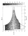
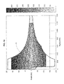
- the figure 1a is a graph of operating points of an electric motor.
- the graph comprises, on the ordinate, the torque delivered by the motor (Nm) as a function of the engine speed (RPM).
- the different operating points are characterized by a gray gradient representing the engine losses (in watt).
- the darkest gradations have the least losses and therefore the best returns.
- the higher the speed, the lower the torque that the engine can offer, at a given yield is low, which is characterized by the decreasing appearance of the operating zones.
- the optimum would obviously be to have an engine with the best returns both in low speed and high speed. Obviously, such an engine is difficult to find and has a high cost.
- Another solution is therefore to choose (at least) two engines, at controlled cost, and whose optimized operating zones (operating zone having the best efficiencies) make it possible to offer an acceptable operating speed range, for example of 0 at 6000 rpm.
- the first electric motor of the device is chosen in order to have an optimized operating zone lying at low speed.
- This operating zone is represented by the shaded area A. This operating zone corresponds, for example, to an "urban" operating mode.
- the second motor of the device according to the invention is chosen so as to have an optimized operating zone situated at high speed; this operating zone is represented by the shaded area B; this operating zone corresponds, for example, to a mode of operation of "road" type.
- the maximum peak power is delivered for a limited period of time (motor thermal limitations, thermal limitation of the power electronics and / or thermal limitation of the battery in discharge). This time limit varies between 10 and 20 seconds depending on the specifications and capabilities of the organs involved. This maximum peak power is normally used for "full load” performance cases (eg full throttle pedal). Of course, this maximum peak power requires cooling means of the electronic part consequently and therefore a high cost. For this reason peak peak power is not the only variable taken into account; in particular the maximum continuous power (which can be delivered for a longer duration) is also taken into account for the choice of the motor.
- the two motors are chosen so as to have a different respective operating zone.
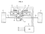
- the driving wheel drive device comprises a first electric motor 1 having an optimized operating zone lying at low speed and a second electric motor 2 having an optimized operating zone lying at high regime.
- the device also comprises a coupling means 20 for coupling and decoupling the driving wheels 22 and 24 of the vehicle, independently to the first motor 1 and the second motor 2. That is to say that the coupling means can, independently, on one side, coupling or decoupling the drive wheels to the engine 1 and, on the other, coupling or decoupling the driving wheels to the engine 2.
- the coupling means 20 comprises two clutches 21 and 23 associated respectively with each of the electric motors 1 and 2.
- the coupling means 20 also comprises a gear element 27 intended to mesh the toothed inlet 28a of a differential 28.
- the meshing of this wheel and the input of the differential has a reduction.
- the differential is, meanwhile, installed on the front or rear axle of the vehicle, depending on whether the drive system is traction or propulsion, the axle comprises, for example, a left wheel 22 and a right wheel 24 , respectively arranged at the end of a left transmission 22a and a right transmission 24a.
- the transmissions 22a and 24a are connected to the differential 28 which distributes the mechanical energy that it receives at its input 28a between the two transmissions 22a and 24b.
- Each of the clutches 21 and 23 is respectively controlled by an actuator 25 and 26, each of the actuators controlling the clutch and / or the disengagement of said clutch 21 and 23.
- the device further comprises a central unit 29 for controlling the actuators 25 and 26 of the clutches 1 and 2.
- the central unit 29 is a computer, for example in the form of a microcontroller. Sensors and analyzers, intended to provide data representative of the operating state of the various elements of the vehicle, are connected to the central unit 29.
- the central unit 29 comprising control and control outputs for controlling the motors as well as the coupling means 20 through the actuators 21 and 23.
- the computer comprises three inputs 29a, 29b and 29c respectively corresponding to an accelerator signal, a braking signal and an estimate of the speed of the vehicle.
- the signals 29a and 29b correspond to commands from the driver.
- these signals emanate from sensors arranged at the level of the acceleration and braking pedals.
- the sensors are position sensors, measuring the depression of the pedal.
- it is provided in the determination of the signals 29a and 29b, to take into account, in addition, the crushing speed of the pedals and the pressure exerted by the driver on said pedals.
- the signal 29c is a signal corresponding to a determination of the longitudinal speed of the vehicle. This determination is, for example, based on the longitudinal speed measured at each wheel of the vehicle. Such a determination is well known in the state of the art and is not more detailed.
- the central unit 29 (or computer), from the input signals, optimally determines the instantaneous operating mode to meet the driver's demand, and limit the power consumption of the vehicle.
- the central unit 29 will choose the mode of operation making it possible to recover, for example, the maximum of energy and thus, to reload the storage system as well as possible.
- energy (not shown) supplying the electric motors, for example a battery of the vehicle.
- the clutches can be replaced by a clutch and an actuator on / off.
- the advantage of jabots is that they are cheap and require little development.
- the central unit 29 determines in which operating zone the driver wishes to bring the vehicle.
- the central unit determines which engine will have the best efficiency in this operating zone and, if necessary, using the coupling system 20, couples the right motor to the drive wheels, and simultaneously decouples the other motor. driving wheels.
- the two engines are superimposed, which makes it possible to have greater acceleration capacity in emergency situations (line insertion maneuvers, overshoot, avoidance, full load start, ).
- the invention provides a transitional step during which the two motors are simultaneously physically connected to the wheels of the vehicle to avoid any jolts during this transition.
- this transitional step is one or two seconds.
- the engine 1 is dimensioned "just needed” to ensure the mobility of the vehicle in the usual operating conditions: takeoff on the flat, followed by “urban” and “suburban” taxi cycles lightly loaded.
- the engine 2, meanwhile, is sized to ensure the operation of the vehicle in sustained "peri-urban” modes, "road” or "highway”.
- Another advantage of a device according to the invention lies in energy recovery.
- the energy recovery can be performed either by a single motor (either the engine 1 or the engine 2) but also by all of the two motors coupled to the drive wheels.
- the electric vehicle equipped with the two-engine architecture described can recover energy (with a single engine or both engines in generator mode as soon as the accelerator pedal is released).
- the braking torques corresponding to the strong generator torque
- the overall need for braking torque which is the translation of the braking demanded by the driver by pressing the brake pedal (displacement, crushing speed and force to the pedal), and which translated by a "requested deceleration", is divided between conventional braking and regenerative braking available with a single engine or with both.
- the energy recovery capacity (and therefore the autonomy of the vehicle) is increased by being able to use the sum of the two engine torques in generator mode because a greater part of the requested deceleration can be absorbed by the regenerative braking two superimposed engines.
- the only regenerative braking is sufficient, which maximizes the energy balance, because all the braking energy is recovered and there is no energy loss. by heating of the brake pads associated with conventional braking.
- the energy recovery capacity depends, of course, on the state of charge of the battery fitted to the vehicle, as well as its capacity for load-absorbing power.
- this parameter is taken into account in the braking strategy described above in order to limit the braking part associated with the motors if the latter have a high state of charge.
- one of the advantages of the invention is to be able to choose which engine to use for energy recovery. Indeed, each engine having different operating areas, the energy level recovered is different depending on the engine used. Thus according to the state of charge of the battery, one chooses one motor rather than another for energy recovery.
- the two electric motors are mounted face to face, coaxially.
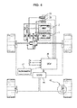
- the device comprises a first electric motor 1 having an optimized operating zone located at low speed, and a second electric motor 2 mounted side by side of the first motor and having an optimized operating zone being at high speed.
- the device also comprises a coupling means 20 for coupling and decoupling the driving wheels 22 and 24 of the vehicle independently to the first electric motor 1 and to the second electric motor 2.
- the device further comprises a reduction system 30 located between the electric motor 2 and the coupling means 20.
- Such a reduction system reduces the cost of the device. Indeed, the cost of an electric motor depends essentially on the maximum speed of this engine. The higher this maximum speed, the more expensive the motor.
- the device makes it possible to choose an electric motor 2 having an optimized operating zone situated at high speed, with a lower maximum speed, thus making it possible to reduce the cost of the electric motor 2, and by this opportunity, the overall cost of the device.
- the two electric motors are arranged side by side.
- the device comprises a decoupled braking control unit (UCFD) 40, connected and controlled by the control unit 29.
- UFD decoupled braking control unit
- the control unit 29 outputs torque control signals, the speed of the electric motors 1 and 2, the control of the clutches (actuators 25 and 26) and the control of the brakes 42 (for example electro-hydraulic brakes). via UCFD 40, ...
- the control unit 29 comprises, as input, control signals of the vehicle, such as: throttle control, brake control, direction control (forward or reverse), "vehicle speed” signal (derived from for example, braking units via the wheel speed sensors) and “slope” (resulting, for example, from an inclinometer 41).
- control signals of the vehicle such as: throttle control, brake control, direction control (forward or reverse), "vehicle speed” signal (derived from for example, braking units via the wheel speed sensors) and “slope” (resulting, for example, from an inclinometer 41).
- the slope signal is also established by a calculation method.
- the principle of this method is the following: to compare at a given speed the actual forward resistance to the forward resistance that one would have at the same speed if one drove at this constant speed, on the flat and with no wind.
- the actual running resistance is then calculated from the total torque to the wheels, via the driving torques (known by the supply voltage and the associated currents).
- the principle of the invention can adapt to the electric motor wheels.
- the engines mounted on the front axle have different characteristics from those mounted on the rear axle.
Landscapes
- Engineering & Computer Science (AREA)
- Transportation (AREA)
- Mechanical Engineering (AREA)
- Power Engineering (AREA)
- Life Sciences & Earth Sciences (AREA)
- Sustainable Development (AREA)
- Sustainable Energy (AREA)
- Chemical & Material Sciences (AREA)
- Combustion & Propulsion (AREA)
- Electric Propulsion And Braking For Vehicles (AREA)
- Hybrid Electric Vehicles (AREA)
Applications Claiming Priority (1)
| Application Number | Priority Date | Filing Date | Title |
|---|---|---|---|
| FR0852974A FR2930743B1 (fr) | 2008-05-05 | 2008-05-05 | Dispositif de propulsion ou de traction electrique d'un vehicule |
Publications (2)
| Publication Number | Publication Date |
|---|---|
| EP2116412A2 true EP2116412A2 (de) | 2009-11-11 |
| EP2116412A3 EP2116412A3 (de) | 2016-01-06 |
Family
ID=40227904
Family Applications (1)
| Application Number | Title | Priority Date | Filing Date |
|---|---|---|---|
| EP09305398.1A Withdrawn EP2116412A3 (de) | 2008-05-05 | 2009-05-05 | Vorrichtung zum Elektroantrieb oder -betrieb eines Fahrzeugs |
Country Status (2)
| Country | Link |
|---|---|
| EP (1) | EP2116412A3 (de) |
| FR (1) | FR2930743B1 (de) |
Cited By (13)
| Publication number | Priority date | Publication date | Assignee | Title |
|---|---|---|---|---|
| WO2013120594A1 (de) * | 2012-02-15 | 2013-08-22 | Dr. Ing. H.C. F. Porsche Aktiengesellschaft | Antriebsstrang eines rein elektrisch antreibbaren kraftfahrzeugs |
| CN104553771A (zh) * | 2013-10-15 | 2015-04-29 | 哈尔滨鑫业电动车技术开发有限公司 | 一种主副电机耦合与增程式驱动系统 |
| WO2015165844A1 (de) * | 2014-04-28 | 2015-11-05 | Bayerische Motoren Werke Aktiengesellschaft | Elektrische antriebseinheit für ein fahrzeug |
| DE102015215393A1 (de) * | 2015-08-12 | 2016-09-29 | Continental Automotive Gmbh | Antriebsstrang für ein elektrisch antreibbares Kraftfahrzeug, elektrisch antreibbares Kraftfahrzeug und Verfahren zum elektrischen Antrieb eines Kraftfahrzeugs |
| CN109747412A (zh) * | 2017-11-07 | 2019-05-14 | 郑州宇通客车股份有限公司 | 一种车辆及其动力系统、减速器 |
| WO2020025775A1 (fr) * | 2018-08-03 | 2020-02-06 | Valeo Embrayages | Systeme de propulsion pour vehicule electrique |
| CN111923745A (zh) * | 2020-08-19 | 2020-11-13 | 华人运通(江苏)技术有限公司 | 扭矩分配方法、装置、电子设备、车辆动力系统和车辆 |
| WO2021187978A1 (en) * | 2020-03-16 | 2021-09-23 | Daf Trucks N.V. | Power management system for electrical vehicles with multiple motors |
| US11279241B2 (en) | 2019-08-01 | 2022-03-22 | System73 Ltd | Multi-motor switching control system and method for increased efficiency and energy savings |
| CN114290890A (zh) * | 2022-01-19 | 2022-04-08 | 山东得普达电机股份有限公司 | 一种使用寿命长的新能源汽车用动力总成 |
| US11407307B2 (en) * | 2020-03-23 | 2022-08-09 | Arvinmeritor Technology, Llc | Drive axle system having multiple electric motors |
| CN118205373A (zh) * | 2024-03-28 | 2024-06-18 | 中山市锵力机电设备科技有限公司 | 一种电动载重车辆、车辆驱动装置及其使用方法 |
| DE102022201391B4 (de) * | 2022-02-10 | 2025-12-04 | Zf Friedrichshafen Ag | Getriebevorrichtung für einen Antriebsstrang eines Kraftfahrzeugs |
Families Citing this family (10)
| Publication number | Priority date | Publication date | Assignee | Title |
|---|---|---|---|---|
| DE202011109790U1 (de) * | 2011-12-05 | 2012-05-07 | Dr. Ing. H.C. F. Porsche Aktiengesellschaft | Antriebsstrang eines rein elektrisch allradbetreibbaren Kraftfahrzeuges |
| DE102011056046B4 (de) * | 2011-12-05 | 2022-05-25 | Dr.Ing.H.C.F.Porsche Aktiengesellschaft | Antriebsstrang eines rein elektrisch allradbetreibbaren Kraftfahrzeuges |
| DE102012202432B4 (de) * | 2012-02-17 | 2017-07-27 | Lisa Dräxlmaier GmbH | Elektroantrieb, Fahrzeug mit einem Elektroantrieb sowie Verfahren zum Betreiben eines Elektroantriebs |
| CN105196863A (zh) * | 2015-10-29 | 2015-12-30 | 厦门市福工动力技术有限公司 | 一种电动汽车驱动装置 |
| US11498431B1 (en) | 2021-07-26 | 2022-11-15 | Rivian Ip Holdings, Llc | Selectable differential drive for a vehicle |
| DE102021209376B4 (de) | 2021-08-26 | 2024-03-21 | Zf Friedrichshafen Ag | Kopplungsvorrichtung für eine Getriebevorrichtung eines Kraftfahrzeugs |
| DE102021006569B4 (de) | 2021-08-26 | 2024-03-21 | Zf Friedrichshafen Ag | Kopplungsvorrichtung für eine Getriebevorrichtung eines Kraftfahrzeugs |
| DE102021006570B4 (de) | 2021-08-26 | 2024-03-21 | Zf Friedrichshafen Ag | Kopplungsvorrichtung für eine Getriebevorrichtung eines Kraftfahrzeugs |
| DE102021006571B4 (de) | 2021-08-26 | 2024-03-21 | Zf Friedrichshafen Ag | Kopplungsvorrichtung für eine Getriebevorrichtung eines Kraftfahrzeugs |
| US12311746B2 (en) * | 2023-01-06 | 2025-05-27 | Dana Heavy Vehicle Systems Group, Llc | Electric axle and control method |
Citations (5)
| Publication number | Priority date | Publication date | Assignee | Title |
|---|---|---|---|---|
| GB2175656A (en) | 1985-05-29 | 1986-12-03 | Unix Co | Change-speed gearing |
| US5289890A (en) | 1991-12-10 | 1994-03-01 | Aisin Aw Co., Ltd. | Drive unit for electric motor vehicle |
| CA2346624A1 (en) | 2000-05-16 | 2001-11-16 | Kabushiki Kaisha Toyoda Jidoshokki Seisakusho | Vehicle powered by a battery |
| US6364806B1 (en) | 1999-07-09 | 2002-04-02 | Daimlerchrysler Ag | Multi-motor drive for motor vehicles |
| FR2866279A1 (fr) | 2004-02-18 | 2005-08-19 | Vehicules Electr Soc D | Systeme d'entrainement des roues motrices d'un vehicule automobile electrique, comprenant deux moteurs et deux batteries |
Family Cites Families (4)
| Publication number | Priority date | Publication date | Assignee | Title |
|---|---|---|---|---|
| IT1241907B (it) * | 1990-11-30 | 1994-02-01 | Digitalia S R L In Ragione Del | Metodo e dispositivo per il controllo della trasmissione in veicoli ad alimentazione elettrica |
| US5934397A (en) * | 1997-01-28 | 1999-08-10 | Schaper; Douglas | Modular land vehicle |
| FR2809352B1 (fr) * | 2000-05-25 | 2002-08-16 | Renault | Groupe motopropulseur d'un vehicule hybride et son procede de commande |
| EP1782988A1 (de) * | 2005-11-04 | 2007-05-09 | MAGNETI MARELLI POWERTRAIN S.p.A. | Hybrid angetriebenes Fahrzeug |
-
2008
- 2008-05-05 FR FR0852974A patent/FR2930743B1/fr active Active
-
2009
- 2009-05-05 EP EP09305398.1A patent/EP2116412A3/de not_active Withdrawn
Patent Citations (5)
| Publication number | Priority date | Publication date | Assignee | Title |
|---|---|---|---|---|
| GB2175656A (en) | 1985-05-29 | 1986-12-03 | Unix Co | Change-speed gearing |
| US5289890A (en) | 1991-12-10 | 1994-03-01 | Aisin Aw Co., Ltd. | Drive unit for electric motor vehicle |
| US6364806B1 (en) | 1999-07-09 | 2002-04-02 | Daimlerchrysler Ag | Multi-motor drive for motor vehicles |
| CA2346624A1 (en) | 2000-05-16 | 2001-11-16 | Kabushiki Kaisha Toyoda Jidoshokki Seisakusho | Vehicle powered by a battery |
| FR2866279A1 (fr) | 2004-02-18 | 2005-08-19 | Vehicules Electr Soc D | Systeme d'entrainement des roues motrices d'un vehicule automobile electrique, comprenant deux moteurs et deux batteries |
Cited By (26)
| Publication number | Priority date | Publication date | Assignee | Title |
|---|---|---|---|---|
| KR20140126710A (ko) * | 2012-02-15 | 2014-10-31 | 독터. 인제니어. 하.체. 에프. 포르쉐 악티엔게젤샤프트 | 순수하게 전기적으로 구동 가능한 자동차의 구동 트레인 |
| JP2015507160A (ja) * | 2012-02-15 | 2015-03-05 | ドクター エンジニール ハー ツェー エフ ポルシェ アクチエンゲゼルシャフトDr. Ing. h.c.F. Porsche Aktiengesellschaft | 純電気駆動可能な自動車のドライブトレイン |
| US9102233B2 (en) | 2012-02-15 | 2015-08-11 | Dr. Ing. H.C. F. Porsche Aktiengesellschaft | Drivetrain of a purely electrically driveable motor vehicle |
| WO2013120594A1 (de) * | 2012-02-15 | 2013-08-22 | Dr. Ing. H.C. F. Porsche Aktiengesellschaft | Antriebsstrang eines rein elektrisch antreibbaren kraftfahrzeugs |
| CN104553771A (zh) * | 2013-10-15 | 2015-04-29 | 哈尔滨鑫业电动车技术开发有限公司 | 一种主副电机耦合与增程式驱动系统 |
| US10773600B2 (en) | 2014-04-28 | 2020-09-15 | Bayerische Motoren Werker Aktiengesellschaft | Electrical drive unit for a vehicle |
| WO2015165844A1 (de) * | 2014-04-28 | 2015-11-05 | Bayerische Motoren Werke Aktiengesellschaft | Elektrische antriebseinheit für ein fahrzeug |
| CN105916716A (zh) * | 2014-04-28 | 2016-08-31 | 宝马股份公司 | 用于交通工具的电驱动单元 |
| DE102015215393A1 (de) * | 2015-08-12 | 2016-09-29 | Continental Automotive Gmbh | Antriebsstrang für ein elektrisch antreibbares Kraftfahrzeug, elektrisch antreibbares Kraftfahrzeug und Verfahren zum elektrischen Antrieb eines Kraftfahrzeugs |
| CN109747412A (zh) * | 2017-11-07 | 2019-05-14 | 郑州宇通客车股份有限公司 | 一种车辆及其动力系统、减速器 |
| FR3084623A1 (fr) * | 2018-08-03 | 2020-02-07 | Valeo Embrayages | Systeme de propulsion pour vehicule electrique |
| CN112739566A (zh) * | 2018-08-03 | 2021-04-30 | 法雷奥离合器公司 | 电动车辆推进系统 |
| CN112739566B (zh) * | 2018-08-03 | 2025-04-22 | 法雷奥离合器公司 | 电动车辆推进系统 |
| WO2020025775A1 (fr) * | 2018-08-03 | 2020-02-06 | Valeo Embrayages | Systeme de propulsion pour vehicule electrique |
| US11970064B2 (en) | 2019-08-01 | 2024-04-30 | System73 Ltd | Multi-motor selection system and method for increased efficiency and energy savings |
| US11279241B2 (en) | 2019-08-01 | 2022-03-22 | System73 Ltd | Multi-motor switching control system and method for increased efficiency and energy savings |
| US11485237B2 (en) | 2019-08-01 | 2022-11-01 | System73 Ltd. | Multi-motor switching system and method for optimized performance |
| US12351040B2 (en) | 2020-03-16 | 2025-07-08 | Daf Trucks N. V. | Power management system for electrical vehicles with multiple motors |
| WO2021187978A1 (en) * | 2020-03-16 | 2021-09-23 | Daf Trucks N.V. | Power management system for electrical vehicles with multiple motors |
| NL2025138B1 (en) * | 2020-03-16 | 2021-10-19 | Daf Trucks Nv | Power management system for electrical vehicles |
| US11407307B2 (en) * | 2020-03-23 | 2022-08-09 | Arvinmeritor Technology, Llc | Drive axle system having multiple electric motors |
| US11975606B2 (en) | 2020-03-23 | 2024-05-07 | Arvinmeritor Technology, Llc | Drive axle system having multiple electric motors |
| CN111923745A (zh) * | 2020-08-19 | 2020-11-13 | 华人运通(江苏)技术有限公司 | 扭矩分配方法、装置、电子设备、车辆动力系统和车辆 |
| CN114290890A (zh) * | 2022-01-19 | 2022-04-08 | 山东得普达电机股份有限公司 | 一种使用寿命长的新能源汽车用动力总成 |
| DE102022201391B4 (de) * | 2022-02-10 | 2025-12-04 | Zf Friedrichshafen Ag | Getriebevorrichtung für einen Antriebsstrang eines Kraftfahrzeugs |
| CN118205373A (zh) * | 2024-03-28 | 2024-06-18 | 中山市锵力机电设备科技有限公司 | 一种电动载重车辆、车辆驱动装置及其使用方法 |
Also Published As
| Publication number | Publication date |
|---|---|
| FR2930743A1 (fr) | 2009-11-06 |
| EP2116412A3 (de) | 2016-01-06 |
| FR2930743B1 (fr) | 2014-04-11 |
Similar Documents
| Publication | Publication Date | Title |
|---|---|---|
| EP2116412A2 (de) | Vorrichtung zum Elektroantrieb oder -betrieb eines Fahrzeugs | |
| EP0898519B1 (de) | Elektrohydraulisches fahrzeug mit energierückgewinnung | |
| EP2222525B1 (de) | Ein elektrisches bremsmoment ausgleichendes bremsverfahren für hybridfahrzeuge | |
| EP3019374B1 (de) | Steuerung des auf das antriebsrad eines hybridkraftfahrzeugs übertragenen drehmoments | |
| WO2008155500A2 (fr) | Procede de controle du freinage recuperatif pour vehicule hybride et/ou a quatre roues motrices et arrangement pour vehicule mettant en oeuvre le procede | |
| FR2801086A1 (fr) | Systeme d'entrainement pour chariot de manutention | |
| WO2014027153A1 (fr) | Procede de limitation de couple d'une machine electrique de vehicule hybride comportant un systeme de controle de vitesse | |
| FR2953772A1 (fr) | Procede de pilotage d'un dispositif de motorisation de vehicule hybride, et dispositif associe | |
| FR3092811A1 (fr) | Procede et systeme de pilotage d’un essieu electrique d’une remorque ou semi-remorque | |
| EP3164285B1 (de) | Verfahren zur steuerung eines hybridantriebssystems für ein hybridfahrzeug | |
| FR2922821A1 (fr) | Dispositif d'accouplement pour une motorisation hybride a fonctionnement selon au moins deux modes electrique/ thermique-electrique destinee a un vehicule. | |
| FR2746352A1 (fr) | Vehicule automobile electrique avec moteur thermique d'appoint | |
| EP2467277B1 (de) | Verfahren und vorrichtung zur verteilung des motordrehmoments zwischen front- und rückteil eines kraftfahrzeuges mit allradantrieb | |
| FR2926771A1 (fr) | Procede et dispositif de freinage mixte electrique hydraulique | |
| EP1431623B1 (de) | Energierückgewinnung während Hochschaltung eines seriellen Hybridfahrzeugs | |
| FR3070347B1 (fr) | Controle d’instants de declenchement d’une marche rampante par des moteur thermique et machine motrice non-thermique d’un vehicule hybride | |
| WO2010012942A2 (fr) | Systeme et procede de commande d'un groupe motopropulseur hybride | |
| EP1590561B1 (de) | Verfahren und vorrichtung zur steuerung der antriebseinheit eines durch einen verbrennungsmotor angetriebenen fahrzeuges | |
| CA2238848C (fr) | Vehicule electro-hydraulique a recuperation d'energie | |
| WO2024133206A1 (fr) | Procédé de commande d'un ensemble électrique d'un véhicule automobile à moteur à combustion interne à boite de vitesses manuelle hybridé | |
| FR3157318A1 (fr) | Système et procédé de commande d’un système de propulsion d’un véhicule hybride | |
| FR3164676A1 (fr) | Procede de reduction de couple d’une machine electrique en cas de manque d’adherence au sol d’un vehicule | |
| EP3931055A1 (de) | Steuerung eines kraftfahrzeugantriebsstranges während der assistierten entschleunigung | |
| FR3097810A1 (fr) | Système de transmission électrique, notamment 48V, pour véhicule doté d’un prolongateur d’autonomie et procédé de pilotage de ce système | |
| WO2013117844A1 (fr) | Procede et systeme de gestion semi-automatisee d'une traction hybride |
Legal Events
| Date | Code | Title | Description |
|---|---|---|---|
| PUAI | Public reference made under article 153(3) epc to a published international application that has entered the european phase |
Free format text: ORIGINAL CODE: 0009012 |
|
| AK | Designated contracting states |
Kind code of ref document: A2 Designated state(s): AT BE BG CH CY CZ DE DK EE ES FI FR GB GR HR HU IE IS IT LI LT LU LV MC MK MT NL NO PL PT RO SE SI SK TR |
|
| PUAL | Search report despatched |
Free format text: ORIGINAL CODE: 0009013 |
|
| AK | Designated contracting states |
Kind code of ref document: A3 Designated state(s): AT BE BG CH CY CZ DE DK EE ES FI FR GB GR HR HU IE IS IT LI LT LU LV MC MK MT NL NO PL PT RO SE SI SK TR |
|
| AX | Request for extension of the european patent |
Extension state: AL BA RS |
|
| RIC1 | Information provided on ipc code assigned before grant |
Ipc: B60L 7/12 20060101ALI20151203BHEP Ipc: B60L 3/04 20060101ALI20151203BHEP Ipc: B60K 1/02 20060101ALI20151203BHEP Ipc: B60K 1/00 20060101ALI20151203BHEP Ipc: B60L 3/00 20060101ALI20151203BHEP Ipc: B60L 15/20 20060101ALI20151203BHEP Ipc: B60L 11/18 20060101ALI20151203BHEP Ipc: B60L 15/32 20060101AFI20151203BHEP |
|
| STAA | Information on the status of an ep patent application or granted ep patent |
Free format text: STATUS: THE APPLICATION IS DEEMED TO BE WITHDRAWN |
|
| 18D | Application deemed to be withdrawn |
Effective date: 20160707 |