EP2116432A2 - Dispositif d'essuie-glaces - Google Patents
Dispositif d'essuie-glaces Download PDFInfo
- Publication number
- EP2116432A2 EP2116432A2 EP09100200A EP09100200A EP2116432A2 EP 2116432 A2 EP2116432 A2 EP 2116432A2 EP 09100200 A EP09100200 A EP 09100200A EP 09100200 A EP09100200 A EP 09100200A EP 2116432 A2 EP2116432 A2 EP 2116432A2
- Authority
- EP
- European Patent Office
- Prior art keywords
- connecting piece
- output shaft
- wiper arm
- wiper
- wiper device
- Prior art date
- Legal status (The legal status is an assumption and is not a legal conclusion. Google has not performed a legal analysis and makes no representation as to the accuracy of the status listed.)
- Withdrawn
Links
- 230000000295 complement effect Effects 0.000 claims abstract description 7
- 239000000463 material Substances 0.000 description 6
- 238000004519 manufacturing process Methods 0.000 description 5
- 230000005540 biological transmission Effects 0.000 description 4
- 238000004381 surface treatment Methods 0.000 description 4
- 229910000831 Steel Inorganic materials 0.000 description 3
- 230000006835 compression Effects 0.000 description 3
- 238000007906 compression Methods 0.000 description 3
- 238000003780 insertion Methods 0.000 description 3
- 230000037431 insertion Effects 0.000 description 3
- 238000000034 method Methods 0.000 description 3
- 239000010959 steel Substances 0.000 description 3
- 150000001875 compounds Chemical class 0.000 description 2
- 238000009434 installation Methods 0.000 description 2
- 239000003973 paint Substances 0.000 description 2
- 239000002966 varnish Substances 0.000 description 2
- 238000005406 washing Methods 0.000 description 2
- 238000005422 blasting Methods 0.000 description 1
- 238000005520 cutting process Methods 0.000 description 1
- 230000001419 dependent effect Effects 0.000 description 1
- 238000013461 design Methods 0.000 description 1
- 238000006073 displacement reaction Methods 0.000 description 1
- 239000000203 mixture Substances 0.000 description 1
- 239000011295 pitch Substances 0.000 description 1
- 238000012805 post-processing Methods 0.000 description 1
- 238000012545 processing Methods 0.000 description 1
- 238000007788 roughening Methods 0.000 description 1
- 238000005488 sandblasting Methods 0.000 description 1
- 238000005507 spraying Methods 0.000 description 1
- 238000012546 transfer Methods 0.000 description 1
Images

Classifications
-
- B—PERFORMING OPERATIONS; TRANSPORTING
- B60—VEHICLES IN GENERAL
- B60S—SERVICING, CLEANING, REPAIRING, SUPPORTING, LIFTING, OR MANOEUVRING OF VEHICLES, NOT OTHERWISE PROVIDED FOR
- B60S1/00—Cleaning of vehicles
- B60S1/02—Cleaning windscreens, windows or optical devices
- B60S1/04—Wipers or the like, e.g. scrapers
- B60S1/32—Wipers or the like, e.g. scrapers characterised by constructional features of wiper blade arms or blades
- B60S1/34—Wiper arms; Mountings therefor
- B60S1/3425—Constructional aspects of the arm
- B60S1/3445—Joints between elements
- B60S1/3459—Joints between elements the element being a mounting head and a shaft
-
- B—PERFORMING OPERATIONS; TRANSPORTING
- B60—VEHICLES IN GENERAL
- B60S—SERVICING, CLEANING, REPAIRING, SUPPORTING, LIFTING, OR MANOEUVRING OF VEHICLES, NOT OTHERWISE PROVIDED FOR
- B60S1/00—Cleaning of vehicles
- B60S1/02—Cleaning windscreens, windows or optical devices
- B60S1/04—Wipers or the like, e.g. scrapers
- B60S1/32—Wipers or the like, e.g. scrapers characterised by constructional features of wiper blade arms or blades
- B60S1/34—Wiper arms; Mountings therefor
- B60S1/3425—Constructional aspects of the arm
- B60S1/3429—Arm pieces
-
- B—PERFORMING OPERATIONS; TRANSPORTING
- B60—VEHICLES IN GENERAL
- B60S—SERVICING, CLEANING, REPAIRING, SUPPORTING, LIFTING, OR MANOEUVRING OF VEHICLES, NOT OTHERWISE PROVIDED FOR
- B60S1/00—Cleaning of vehicles
- B60S1/02—Cleaning windscreens, windows or optical devices
- B60S1/56—Cleaning windscreens, windows or optical devices specially adapted for cleaning other parts or devices than front windows or windscreens
- B60S1/58—Cleaning windscreens, windows or optical devices specially adapted for cleaning other parts or devices than front windows or windscreens for rear windows
- B60S1/583—Cleaning windscreens, windows or optical devices specially adapted for cleaning other parts or devices than front windows or windscreens for rear windows including wiping devices
Definitions
- the invention relates to a windshield wiper device, in particular for a rear window wiper of a motor vehicle having a wiper motor, which has one or more output shafts and with one or more wiper arms, which are fastened in each case via a fastening mechanism to an end portion of the output shaft.
- Windscreen wiper device of the above type are well known and for example in the DE 10 2006 007 350 A1 described.
- a windscreen wiper for motor vehicles is known, which are mounted on frusto-conical end portions of output shafts.
- the knurling of the frusto-conical end portion engages a frusto-conical hub at one end of a wiper arm of the windshield wiper.
- the knurling has the task of preventing a rotation of the windscreen wiper relative to the output shaft.
- an external thread is formed at its protruding from the hub end to which a nut is screwed, so that no longer rotate due to the thereby engaging knurls of the wiper arm relative to the output shaft, since the hub of the wiper arm by the tightening of the nut is pressed into the knurling of the output shaft.
- a disadvantage of this structure is, on the one hand, that the attachment of the windshield wiper in the final assembly additional parts such as nuts, washers and the like must be kept by the customer. Such attachment also requires a lot of time. In the final assembly, variances in the connection can occur because each customer uses his own components and tools and so, for example, different sized torques are introduced during assembly in the knurled joint.
- the knurling geometry also involves problems both during production and during power transmission.
- the knurling geometry can not be produced in a reproducible manner since different material properties along the component are produced by the material processing associated with the introduction of the knurling.
- Another problem with such a knurling is that very high forces can be transmitted via the knurl, which can lead to the fact that when exceeding a torque to be transmitted the associated high forces are introduced into the wiper system and possibly irreparable damage can cause.
- missuse in that the maximum torque to be transmitted is also limited by the system.
- a missuse may occur, for example, when a large force is applied to the wiper arm, as e.g. the case is when the wiper arm engages in a washer on one of the washing brushes and the washing brush pulls on the wiper arm, so that the rod is rotated beyond the intended wiping angle out, or if large amounts of snow from the roof of the motor vehicle on the front or rear window slip on the wiper arm.
- the fastening mechanism has a connecting piece, at one end of the wiper arm can be pushed and at the other end a complementary formed to the end portion of the output shaft recess is provided, in which the output shaft for attachment of the fastening mechanism to the wiper motor can be inserted, wherein between the connecting piece and the end portion of the output shaft in the assembled state, a frictional connection is formed.
- the maximum transmittable torque is limited by the coefficient of friction, which is established by the frictional connection between the output shaft and connecting piece, so that when a maximum value is exceeded, the connecting piece slips on the output shaft. This prevents excessive forces being introduced into the system, which could otherwise damage the system.
- a particularly simple form of attachment of the wiper arm to the fastening mechanism is achieved in that the wiper arm is formed in its mounting region so that it can be pushed onto the connecting piece such that a frictional connection is established between the wiper arm and the connecting piece.
- the assembly may be provided in one embodiment, that adjusts the frictional connection between the connecting piece and the output shaft by the mounting of the wiper arm on the mounting mechanism.
- This can for example be achieved in that the recess in the connecting piece and the diameter of the end portion of the output shaft are designed so that a close fit, the alleged residual play is overcome in the assembled state that the connector when sliding the wiper arm in Area of the recess is compressed by a few microns.
- the frictional connection between the wiper arm and connecting piece is formed by two complementary conical surfaces, which form a frictional connection in the mounted state. This allows a particularly simple installation of the wiper arm on the connector and a homogeneous Compression of the connector in the insertion of the output shaft for adjusting the frictional connection.
- the connecting piece may have a projection on which an external thread is formed, onto which a fastening nut can be screwed. This represents a particularly simple way to advance the wiper arm on the connector so that a frictional connection between the wiper arm and connector is reliably established.
- a stop is formed on the connecting piece, over which the axial path of the fastening nut can be limited, a force application independent of the tightening torque of the screw can be ensured on the wiper arm.
- This stop can also be arranged adjustably on the connecting piece in order to be able to set different positions of the wiper arm on the connecting piece in a reproducible manner and thus different Reib shimmerer in the contact area and thus also different maximum moments to be transmitted.
- a locking ring in particular a spring washer, interposed between mounting nut and wiper arm for applying a reproduced force on the wiper arm.
- a contact surface is provided on the connecting piece, via which the path of the wiper arm on the connecting piece is axially limited.
- Reibwertordigerndes means may be provided in a further embodiment between the connecting piece and the output shaft and / or between the connecting piece and the wiper arm a Reibwertordigerndes means.
- This Reibwertsteigernde means may be applied, for example, by spraying on both the output shaft or at the recess of the connector, in particular in the contact area between the recess and output shaft, by applying a friction-enhancing paint.
- the coefficient of friction and thus the resulting friction torque can also be formed by changing the surface in the output shaft and / or the recess within the connector or even the contact area between the connector and wiper arm. This can be effected for example by surface treatment such as roughening or by a blasting process such as sand blasting. Of course, combinations of Reibwertsteigernden layers and a surface treatment are conceivable.
- the friction-increasing means is formed by a friction sleeve or a friction cone inserted between the connecting piece and the output shaft and / or between the connecting piece and the wiper arm. If this variant is selected, it is relatively easy to use the same parts for different motor vehicles with, for example, different maximum speeds and to set different maximum limits of the maximum torque to be transmitted via the fastening mechanism only by replacing the friction sleeve.
- the connecting piece and the wiper arm and between the connecting piece and the output shaft it is possible to choose different coefficients of friction between the connecting piece and the wiper arm and between the connecting piece and the output shaft. This opens up the possibility of determining the location of slippage when the maximum torque to be transmitted is exceeded by making the friction coefficient at the corresponding connection region smaller. For example, if there is slippage at the contact area between the wiper arm and connector desired, so there is a friction torque is set, which is lower than the friction torque between the connecting piece and the output shaft. Conversely, the friction between the wiper arm and connector is selected to be higher than between the connecting piece and the output shaft when slipping in the contact area between the output shaft and connector is desired.
- the setting of the coefficient of friction can also be achieved either by surface treatment, by applying Reibwertsteigernden materials or by inserting different friction sleeves or combinations thereof.
- FIG. 1 shows a fastening mechanism 1 for attaching a wiper arm 2 to an end portion of an output shaft 3 of a wiper motor of a windshield wiper device not shown in detail.
- the mounting mechanism 1 has a connecting piece 4, in which a complementary to the end portion 3a of the output shaft 3 trained insertion region is provided in the form of a recess 5, in which the end portion 3a is inserted, wherein between the connecting piece 4 and the end portion 3a of the output shaft 3 in mounted state of the windscreen wiper device sets a frictional connection.
- the wiper arm 2 is mounted on the connecting piece 4.
- the connecting piece 4 is provided in the contact region with the wiper arm 2 with a wedge surface 4a, which is complementary to the contact area facing wedge surface 2a of the wiper arm 2, so that in the assembled state between the wiper arm 2 and connector 4 forms a frictional connection.
- the connecting piece 4 has a projection 7, on which an external thread 8 is formed, onto which a fastening nut 9 is screwed, via which the wiper arm 2 in the axial direction by applying a tightening torque along the connecting piece 4 in axial Direction can be moved and brought into the desired position and fixed in this position.
- a stop 10 on the connecting piece 4 provided.
- the tightening torque acting from outside on the fastening nut 9 can be increased without the axial force acting on the wiper arm 2 being changed as a result. This ensures that the introduction of force via the fastening nut 10 is kept constant, even if the tightening torque of the fastening nut 9 varies from assembly process to assembly process and in particular a maximum tightening torque is exceeded.
- the FIG. 2 shows a fastening mechanism according to the FIG. 1 in which a friction-increasing means are provided to increase the coefficient of friction between the connecting piece 4 and the wiper arm 2 or between the connecting piece 4 and the output shaft 3.
- the output shaft 3 was sprayed with a friction varnish to increase the coefficient of friction and thus the friction torque and thus the maximum torque to be transmitted between the connecting piece 4 and the output shaft 3 before mounting the fastening mechanism 1.
- a friction-increasing friction sleeve 13 is used between the wiper arm 2 and the connecting piece 4 .
- the friction values achieved by the friction sleeves can be different depending on the selected sleeve material, so that it is possible to determine the desired position of slipping by selecting the material or the material composition also when exceeding a maximum torque to be transmitted.
- the wiper drive must be designed to be more stable than the maximum defined transmission torque of the friction connection between wiper arm 2 and connector 4 and between connector 4 and end portion 3a of the output shaft 3, depending on which of the compounds has the lower coefficient of friction. If the maximum torque to be transmitted has been exceeded and thereby a slippage of the corresponding frictional connection caused by the connection was released by the action of the external moment, the connection can be easily restored by being tightened again after being in the right position was brought. The system is then fully functional again. This ensures that even when too much external moment is applied to the wiper arm, the various parts of the wiper drive can not be damaged.
- the mounting of the wiper arm 2 to the attachment mechanism 1 proceeds as follows. First, the end portion 3a of the output shaft 3 is inserted into the connector 4. The end portion 3a of the output shaft 3 and the recess 5 in the connecting piece 4 are designed so that a close fit between the connecting piece 4 and output shaft 3 sets. Then, the wiper arm 2 is pushed onto the connecting piece 4 and moved downwards over the wedge surfaces 4a of the connecting piece along the connecting piece 4. In order to achieve a frictional connection between the wiper arm 2 and the wedge surfaces 4 a of the connecting piece, which ensures that a frictional connection between the connecting piece 4 and the end portion 3 a of the output shaft 3, the fastening nut 9 on the projection 7 of the connecting piece 4th screwed on and moved down.
- the resulting axial force component is converted to the wedge surface between the wiper arm 2 and connector 4 in a transverse component.
- This creates a normal force between the connecting piece 4 and the end portion 3a of the output shaft 3, resulting in a maximum torque to be transmitted between the connecting piece 4 and end portion 3a of the output shaft 3 from the formula Mr ⁇ x F N xr yields, where the radius of the output shaft 3 and ⁇ is the coefficient of friction between the output shaft 3 and recess 5.
- This normal force ensures that the connector in the area the recess 5 is compressed, whereby the normal force between the connecting piece 4 and the output shaft 3 increases.
- the normal force between the connecting piece 4 and the output shaft 3 can be varied and thus adjusted.
- the fastening nut 9 is in this embodiment as long as moved on the projection 7 of the connecting piece 4 until it abuts against the stop 10, which limits the axial path. If the stop 10 is reached, the tightening torque can be further increased from the outside, without the axial force of the spring washer 12 increasing on the connecting piece 4.
- the normal force F N between wiper arm 2 and connecting piece 4 can also be varied by varying the clamping cone increase and the tightening torque applied to the fastening nut 9, so that it is possible to transfer a maximum of different maximum by simply exchanging the connecting piece or inserting connecting pieces with different clamping cone pitches Adjust friction moments.
- the transmission torque for a connection as in FIG. 1 can be determined as follows.
- Both the output shaft 3 and the connecting piece 4 and the wiper arm 2 are made of steel.
- a combination steel / steel which is greased and paired with high surface quality.
- this torque range is too low to provide an optimal wiping field.
- a friction sleeve 13 is inserted.
- the coefficient of friction, which results from the combination of the sandblasted end portion 3a of the output shaft 3 with the Reibwerterhöernden paint 12 is smaller than the friction coefficient 13 through the friction coefficient, so that when exceeding the friction coefficient between the end portion 3a of the output shaft 3 and Connecting piece 4 resulting maximum torque slipping in the contact region of the output shaft 3 and connector 4 causes.
- a friction sleeve is used with a lower coefficient of friction or the surface treatment at the end portion 3a of the output shaft 3 and / or at the recess of the connector selected so that a larger Frictional torque is formed between the latter.
- a further friction sleeve 13 are used, which has a higher coefficient of friction than the friction sleeve 13 between the wiper arm 2 and connector 4 or even the friction sleeve between wiper arm 2 and connector 4 are removed.
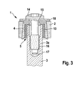
- FIG. 3 shows an alternative embodiment of a fastening mechanism 1, in which the fastening of the connecting piece 4 via a fastening means takes place here in the form of a fastening screw 14.
- the connecting piece 4 For mounting the connecting piece on the end portion 3a of the drive shaft, the connecting piece 4 has a recess 5 into which the end portion 3a of the drive shaft 3 is inserted.
- opening 15 is provided, through which the fastening screw 14 is inserted, to be subsequently screwed into a provided with a threaded 16 in the end portion 3a of the drive shaft 3 bore 17.
- a thrust washer 18 is provided in this embodiment, about which sets by tightening the mounting screw 14, a frictional connection between the wiper arm 2 and connector 4, for example by the tightening torque of the mounting screw 14 is applied defined.
- the provision of the fastening screw 14 for fastening the connecting piece 4 within the bore 16 with a thread 15 in the region below the clamping between the connecting piece 4 and end portion 3a of the drive shaft 3 has the advantage that the long shaft of the fastening screw 14 has an elongation in the hook ' allowed area. As a result, the risk of loosening the fastening screw 14 can be reduced even with changing loads.
- By displacement of the attachment point in the end portion 3a of the drive shaft 3 is further eliminated in the FIG. 1 shown by the fastening nut 11 caused high structure.
- the wiper arm 2 does not fall off the shaft even if the connection between connecting piece 4 and wiper arm 2 or drive shaft 3 and connecting piece 4 is released, as long as the fastening screw 14 is not completely unscrewed from the thread 15.
Landscapes
- Engineering & Computer Science (AREA)
- Mechanical Engineering (AREA)
- Transmission Devices (AREA)
- Connection Of Motors, Electrical Generators, Mechanical Devices, And The Like (AREA)
Applications Claiming Priority (1)
| Application Number | Priority Date | Filing Date | Title |
|---|---|---|---|
| DE102008001685A DE102008001685A1 (de) | 2008-05-09 | 2008-05-09 | Scheibenwischervorrichtung |
Publications (2)
| Publication Number | Publication Date |
|---|---|
| EP2116432A2 true EP2116432A2 (fr) | 2009-11-11 |
| EP2116432A3 EP2116432A3 (fr) | 2017-10-04 |
Family
ID=40940629
Family Applications (1)
| Application Number | Title | Priority Date | Filing Date |
|---|---|---|---|
| EP09100200.6A Withdrawn EP2116432A3 (fr) | 2008-05-09 | 2009-03-25 | Dispositif d'essuie-glaces |
Country Status (2)
| Country | Link |
|---|---|
| EP (1) | EP2116432A3 (fr) |
| DE (1) | DE102008001685A1 (fr) |
Cited By (1)
| Publication number | Priority date | Publication date | Assignee | Title |
|---|---|---|---|---|
| DE102012201063A1 (de) | 2012-01-25 | 2013-07-25 | Robert Bosch Gmbh | Wischvorrichtung |
Families Citing this family (1)
| Publication number | Priority date | Publication date | Assignee | Title |
|---|---|---|---|---|
| DE102012212295B4 (de) * | 2012-07-13 | 2014-08-21 | Aktiebolaget Skf | Verfahren zum Erzeugen einer ein Drehmoment übertragenden Verbindung und drehmomentübertragende Anordnung |
Citations (1)
| Publication number | Priority date | Publication date | Assignee | Title |
|---|---|---|---|---|
| DE102006007350A1 (de) | 2005-12-28 | 2007-07-05 | Robert Bosch Gmbh | Scheibenwischervorrichtung |
Family Cites Families (1)
| Publication number | Priority date | Publication date | Assignee | Title |
|---|---|---|---|---|
| GB497027A (en) * | 1937-06-11 | 1938-12-12 | Lucas Ltd Joseph | Improvements relating to motor vehicle wind screen wipers |
-
2008
- 2008-05-09 DE DE102008001685A patent/DE102008001685A1/de not_active Ceased
-
2009
- 2009-03-25 EP EP09100200.6A patent/EP2116432A3/fr not_active Withdrawn
Patent Citations (1)
| Publication number | Priority date | Publication date | Assignee | Title |
|---|---|---|---|---|
| DE102006007350A1 (de) | 2005-12-28 | 2007-07-05 | Robert Bosch Gmbh | Scheibenwischervorrichtung |
Cited By (1)
| Publication number | Priority date | Publication date | Assignee | Title |
|---|---|---|---|---|
| DE102012201063A1 (de) | 2012-01-25 | 2013-07-25 | Robert Bosch Gmbh | Wischvorrichtung |
Also Published As
| Publication number | Publication date |
|---|---|
| DE102008001685A1 (de) | 2009-11-12 |
| EP2116432A3 (fr) | 2017-10-04 |
Similar Documents
| Publication | Publication Date | Title |
|---|---|---|
| EP2490923B1 (fr) | Dispositif d'essuie-glaces | |
| DE102017217631B3 (de) | Aktuator einer Lenkung sowie steer-by-wire-Lenkung eines Kraftfahrzeuges | |
| EP3423727B1 (fr) | Liaison arbre-moyeu | |
| DE102005054461B4 (de) | Vorrichtung zum schwenkbeweglichen Verbinden von mindestens zwei Bauteilen und Verfahren zur Montage der Vorrichtung | |
| WO2017118575A1 (fr) | Ensemble d'étanchéite pour une compensation de longueur d'un arbre articulé et arbre articulé | |
| EP2276653B1 (fr) | Dispositif essuie-glace | |
| WO2011009440A1 (fr) | Dispositif de fixation et système de fixation | |
| DE602004007472T2 (de) | Motorisierter Aktuator für Fahrradgangschaltung, mit kontrolliertem Reibungsmechanismus | |
| EP1137558A1 (fr) | Dispositif pour fixer un bras d'essuie-glace sur un arbre de commande | |
| WO2002086336A1 (fr) | Ecrou permettant de limiter un couple de serrage effectif et procede correspondant | |
| EP2116432A2 (fr) | Dispositif d'essuie-glaces | |
| DE202011109172U1 (de) | Schraubverbindung, Brille | |
| DE102008061854A1 (de) | Scharnier | |
| EP1350041A1 (fr) | Dispositif de fixation de piston | |
| WO2011160240A1 (fr) | Corps d'arbre comprenant un segment à contour externe moleté longitudinalement | |
| DE102020211158B4 (de) | Passverbindung | |
| DE10109660B4 (de) | Sicherungsring und Befestigungsvorrichtung für eine Welle-Nabe-Verbindung | |
| EP3838634B1 (fr) | Essieu à bras tirés pour remorques de véhicule | |
| DE102017214320B4 (de) | Aktuator einer Hinterachslenkung für ein Kraftfahrzeug | |
| DE10259956B4 (de) | Scheibenwischvorrichtung, insbesondere für ein Kraftfahrzeug | |
| DE29821143U1 (de) | Abzieher mit schnellverstellbarer Druckspindel | |
| DE19836680C2 (de) | Radlagereinheit für ein angetriebenes Rad eines Kraftfahrzeuges | |
| DE102018213776A1 (de) | Aktuator einer Hinterachslenkung für ein Kraftfahrzeug | |
| EP3692278A1 (fr) | Actionneur de direction, notamment pour direction d'essieu arrière d'un véhicule à moteur | |
| WO2018036644A1 (fr) | Élément d'assemblage, procédé et dispositif pour assembler au moins deux composants |
Legal Events
| Date | Code | Title | Description |
|---|---|---|---|
| PUAI | Public reference made under article 153(3) epc to a published international application that has entered the european phase |
Free format text: ORIGINAL CODE: 0009012 |
|
| AK | Designated contracting states |
Kind code of ref document: A2 Designated state(s): AT BE BG CH CY CZ DE DK EE ES FI FR GB GR HR HU IE IS IT LI LT LU LV MC MK MT NL NO PL PT RO SE SI SK TR |
|
| AX | Request for extension of the european patent |
Extension state: AL BA RS |
|
| PUAL | Search report despatched |
Free format text: ORIGINAL CODE: 0009013 |
|
| AK | Designated contracting states |
Kind code of ref document: A3 Designated state(s): AT BE BG CH CY CZ DE DK EE ES FI FR GB GR HR HU IE IS IT LI LT LU LV MC MK MT NL NO PL PT RO SE SI SK TR |
|
| AX | Request for extension of the european patent |
Extension state: AL BA RS |
|
| RIC1 | Information provided on ipc code assigned before grant |
Ipc: B60S 1/34 20060101AFI20170828BHEP |
|
| AKY | No designation fees paid | ||
| AXX | Extension fees paid |
Extension state: BA Extension state: RS Extension state: AL |
|
| REG | Reference to a national code |
Ref country code: DE Ref legal event code: R108 |
|
| STAA | Information on the status of an ep patent application or granted ep patent |
Free format text: STATUS: THE APPLICATION IS DEEMED TO BE WITHDRAWN |
|
| 18D | Application deemed to be withdrawn |
Effective date: 20180405 |