EP2116488B1 - Dispositif de courroie transporteuse avec un dispositif de direction de courroie spécifique - Google Patents
Dispositif de courroie transporteuse avec un dispositif de direction de courroie spécifique Download PDFInfo
- Publication number
- EP2116488B1 EP2116488B1 EP08155642A EP08155642A EP2116488B1 EP 2116488 B1 EP2116488 B1 EP 2116488B1 EP 08155642 A EP08155642 A EP 08155642A EP 08155642 A EP08155642 A EP 08155642A EP 2116488 B1 EP2116488 B1 EP 2116488B1
- Authority
- EP
- European Patent Office
- Prior art keywords
- belt
- run
- conveyor belt
- steering
- rollers
- Prior art date
- Legal status (The legal status is an assumption and is not a legal conclusion. Google has not performed a legal analysis and makes no representation as to the accuracy of the status listed.)
- Not-in-force
Links
- 230000000694 effects Effects 0.000 claims description 8
- 230000001154 acute effect Effects 0.000 claims description 3
- 238000005096 rolling process Methods 0.000 claims 1
- 238000011144 upstream manufacturing Methods 0.000 abstract description 3
- 238000010276 construction Methods 0.000 description 1
- 230000007423 decrease Effects 0.000 description 1
- 230000000750 progressive effect Effects 0.000 description 1
- 238000004904 shortening Methods 0.000 description 1
Images


Classifications
-
- B—PERFORMING OPERATIONS; TRANSPORTING
- B65—CONVEYING; PACKING; STORING; HANDLING THIN OR FILAMENTARY MATERIAL
- B65G—TRANSPORT OR STORAGE DEVICES, e.g. CONVEYORS FOR LOADING OR TIPPING, SHOP CONVEYOR SYSTEMS OR PNEUMATIC TUBE CONVEYORS
- B65G15/00—Conveyors having endless load-conveying surfaces, i.e. belts and like continuous members, to which tractive effort is transmitted by means other than endless driving elements of similar configuration
- B65G15/60—Arrangements for supporting or guiding belts, e.g. by fluid jets
-
- B—PERFORMING OPERATIONS; TRANSPORTING
- B65—CONVEYING; PACKING; STORING; HANDLING THIN OR FILAMENTARY MATERIAL
- B65G—TRANSPORT OR STORAGE DEVICES, e.g. CONVEYORS FOR LOADING OR TIPPING, SHOP CONVEYOR SYSTEMS OR PNEUMATIC TUBE CONVEYORS
- B65G15/00—Conveyors having endless load-conveying surfaces, i.e. belts and like continuous members, to which tractive effort is transmitted by means other than endless driving elements of similar configuration
- B65G15/60—Arrangements for supporting or guiding belts, e.g. by fluid jets
- B65G15/62—Guides for sliding belts
-
- B—PERFORMING OPERATIONS; TRANSPORTING
- B65—CONVEYING; PACKING; STORING; HANDLING THIN OR FILAMENTARY MATERIAL
- B65G—TRANSPORT OR STORAGE DEVICES, e.g. CONVEYORS FOR LOADING OR TIPPING, SHOP CONVEYOR SYSTEMS OR PNEUMATIC TUBE CONVEYORS
- B65G39/00—Rollers, e.g. drive rollers, or arrangements thereof incorporated in roller-ways or other types of mechanical conveyors
- B65G39/10—Arrangements of rollers
- B65G39/12—Arrangements of rollers mounted on framework
- B65G39/16—Arrangements of rollers mounted on framework for aligning belts or chains
Definitions
- the present invention relates to a conveyor belt device comprising a frame with a support for a belt and the objects to be moved with the latter, and an endless belt, a drive for said belt, reversing rollers for said belt, and steering rollers which determine the position of said belt on said frame.
- a conveyor belt device of this type is generally known in the prior art. In particular with relatively long belts, positioning the belt with respect to the drive may cause problems. When such relatively long belts move with respect to the frame, this tends not always to be in the desired location. Therefore, the use of steering rollers is proposed in the prior art.
- these steering rollers can only be arranged in the return run as the conveying surface has to be kept free for the objects to be moved, see US-A-2 725 757 , for example. It has been found that in the case of a relatively long belt, there is a need for further control of the conveying belt run of the belt in a conveying device.
- said steering rollers engage with the conveying belt run, have an axis of rotation which is substantially perpendicular to the plane of the conveying belt run, at least partially extend in an interruption in said support in the longitudinal direction, which steering rollers are each provided with a groove, with a side wall of said groove engaging with the conveying belt run, said side wall extending at an acute angle ( ⁇ ) with respect to the plane of movement of the conveying belt run, with the distance (b) between the mutually opposite bottoms of the grooves of said steering rollers being substantially greater than the width (a) of the conveying belt run.
- the steering rollers are provided in the conveying run of the belt; that is to say, contrary to the prior art, it is the conveying belt run which is corrected and not the return run.
- the steering rollers are embodied in a particular way.
- the latter are each provided with a groove having an oblique side wall over which a part of the respective belt run runs.
- the distance between the bottoms of the grooves of two mutually opposite steering rollers is greater than the width of the respective belt run.
- the belt run is not closed in between the bottoms of the grooves of the steering rollers, but can still move between the latter to a limited extent. That is to say, the respective belt run finds a way between two mutually opposite steering rollers.
- the belt run moves towards the axis of rotation of one steering roller, the belt run will, as a result of the sloping design of the respective part of said steering roller over which the belt run runs, experience an increasingly large force in the direction away from said axis the closer said belt run moves towards the bottom of the respective groove, while, for opposite reasons, the belt run will at the same time experience an increasingly smaller force in the direction away from the axis of the steering roller situated opposite.
- a stable balance is achieved between two mutually opposite steering rollers.
- As the bottom of the groove does not press onto the side of the belt, a shortening of the service life of the belt, as occurs with prior art edge rollers, is prevented.
- the support for the conveying belt run and objects to be conveyed is interrupted for the steering rollers and the belt run is deflected to a greater or lesser extent by the oblique side walls of the grooves of said steering rollers from the edges of said interruption.
- the invention relates in particular to a conveyor belt device for conveying objects which are wider than the respective belt. This results in a saving for the cost of the belt.
- the steering rollers will be in the plane of transport of an object to be conveyed.
- supporting rollers are used at the edges of the interruption in the support for the conveying belt run and objects to be moved in order to deflect the belt from its plane of movement to a plane in which the grooves of the steering rollers are situated. If such supporting rollers are used both in the upstream and downstream direction, the upper surface of the steering rollers is preferably level with the upper surface of the conveying belt run.
- the respective conveying belt run will be deflected from its plane of movement by the grooves of the steering rollers which are in a different plane to the upper side of the supporting rollers.
- Using said supporting rollers creates advantageous steering forces as a result of the fact that, due to the uneven deflection of the relevant belt run by the oblique side walls of the mutually opposite grooves of the steering rollers, the angle of contact of the relevant belt run with the supporting rollers will vary asymmetrically across the width of the belt run.
- the above-described acute angle, at which the side wall of the groove of the steering roller, with which the belt engages extends, is preferably between 10° and 45°.
- This angle may vary, depending on the distance of the side wall to the axis of rotation of the relevant steering roller. In such a case, the angle preferably becomes increasingly larger as the distance to this axis becomes smaller and may, in an extreme case, even be parallel to this axis. As a result thereof, a progressive action of the steering force acting on the belt is achieved.
- the length of the conveying run of the belt is at least 100x and more particularly at least 300x greater than the width.
- the steering rollers may be arranged opposite one another and offset with respect to one another. Preferably, however, they are in a plane which is perpendicular to the direction of transport.
- the steering rollers and, more particularly, the axes of rotation thereof are preferably situated in a plane which is perpendicular to the direction of transport and in the centre of the interruption in the support for the conveying belt run and objects to be moved.
- the embodiment can be used at any suitable position along a conveying belt run and also at several positions along a conveying belt run.
- the invention can be used in a non-conveying belt run and can, optionally, also be used in the associated conveying belt run.
- the invention can be used both on straight sections and in bends of belts. If a belt makes a bend in its plane of movement, it is sufficient to use steering rollers on one side of said belt.
- the invention can also be used in a conveyor device in which the conveying belt run does not move in one plane, in which the steering rollers keep said belt run tensioned and in position in an inside bend and objects to be moved can pass freely.
- a supporting roller may also be a reversing roller of the conveyor belt device.
- a conveyor belt device is diagrammatically illustrated and denoted overall by reference numeral 1. It comprises a relatively narrow belt of which only the conveying run 2 is indicated. The latter moves over a frame 3 in the usual way via reversing rollers and is provided with a drive for the belt in any suitable way.
- the frame 3 has a support 4 for the belt 2 and objects 6 to be moved on top of it, such as pot plants held in dishes 5.
- steering rollers are present.
- the steering rollers 8 can be rotated about an axis of rotation 9 which is substantially perpendicular to the plane of transport.
- Each steering roller comprises a base body which is provided with a groove 10, and has a bottom 12 and an oblique wall 11.
- the steering rollers are preferably arranged directly opposite one another and it should be understood that it is possible, for example at a bend, to provide steering rollers on only one side of the belt and/or to provide the steering rollers, viewed in top view in the direction of transport, offset with respect to one another.
- the figures show that the conveying run 2 of the belt is guided in the grooves 10 of the steering rollers.
- the width of run 2 is denoted by the letter a and the distance between the bottoms 12 of opposite steering rollers is denoted by the letter b.
- the difference between a and b is preferably at least 1 cm.
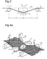
- Fig. 3 shows, the oblique wall 11 of a steering roller 8 is always in a different plane to the plane of movement of the engaged belt run in order to allow a pressure force to be created between the wall and said belt run, and, as a result, the belt run is deflected at the edges of the interruption in its support from its plane of movement.
- supporting rollers 16 and 17 are preferably used for this deflecting action.
- the belt 2 is significantly narrower than the plane of transport of the dish 5. This makes it necessary to move the steering rollers in such a manner that the dish can be moved over the steering roller 8.
- Fig. 3 shows the details of the arrangement thereof.
- the embodiment is such that supporting rollers 16 and 17 are provided and that line 18, which forms the plane of transport of the belt run 2 outside the area of the steering rollers, is level with the upper side of the steering roller 8. Deflecting the belt run 2 via the supporting rollers 16 and 17 to the wall 11 of the steering roller 8 firstly leads to a greater degree of contact with the wall 11 of the steering rollers which results in a more pronounced correction, and, on the other hand, at the same time to a significant correction by the supporting rollers, as is illustrated by means of Fig. 4 .
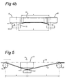
- Figs. 4a, b show a steering device comprising two steering rollers 8 and the supporting rollers 16 and 17 which, viewed in the plane of transport over on two main axes, are arranged symmetrically.
- the belt run 2 passes over the supporting rollers 16 and 17 at an angle of contact d.
- the angle of contact has a symmetric profile across the width of said belt run with equal boundary values d1 and d2. If the belt run deviates from the ideal position, it is moved further out of its original plane of movement to a greater degree by the one steering roller than by the other steering roller, which results in the angle of contact across the width of the belt run varying asymmetrically with unequal boundary d3 and d4.
- the axis of rotation of the steering roller 9 is perpendicular to the plane of transport in all directions and is situated in the centre of the interruption of the plane of transport, which is a result of the interruption in the support for the conveying belt run and objects to be moved.
- Fig. 5 shows that it is possible to place the steering roller 8 closer to the upstream supporting roller 16 than to the downstream supporting roller. This results in a greater degree of correction at the entry part of the steering roller than at the exit part.
- the same effect can be achieved by adjusting the position of the axes of rotation of the steering rollers, as illustrated in Fig. 6 , where in this case a different angle ⁇ with respect to the plane of transport has been chosen which is preferably greater than 95°.
- the degree of contact with the steering roller is greater at the entry part of the belt run than at the exit part.
- an embodiment according to Figs. 5 and 6 is more suitable for conveyors with substantially one direction of transport.
- Fig. 7 shows a variant of the steering roller in which the above-described angle ⁇ varies depending on the position of wall part 27 of steering roller 28 with respect to the axis 29.
- the curved shape results in a gradually increasing corrective force which is exerted by the steering roller on the belt run.
- Fig. 8 shows an arrangement in which, contrary to the arrangement in Fig. 2 , the axes of rotation 9 of the mutually opposite steering rollers 8 are not perpendicular with respect to the plane of transport 18, but form an angle ⁇ with the latter which is greater than 90° and preferably greater than 95°.
- the upper side of the steering rollers is not flat, but conical and forms an angle with respect to the axis of rotation of the same magnitude as the abovementioned angle ⁇ . Both upper sides now have a common tangent line which is level with the plane of transport. As a result thereof, a passing object only rests on a part of the steering rollers which moves in the direction of transport, so that this object is driven and wear resulting from contact between the object and the steering roller is minimized.
- the lower part of the steering roller that is to say the other wall of the groove, is not relevant and this may therefore have any suitable embodiment.
Landscapes
- Engineering & Computer Science (AREA)
- Mechanical Engineering (AREA)
- Structure Of Belt Conveyors (AREA)
Claims (20)
- Dispositif de courroie transporteuse (1) comprenant un cadre (3) avec un support (4) pour une courroie et les obj ets à déplacer avec cette dernière, et une courroie sans fin (2), un entraînement pour ladite courroie, des cylindres de renversement pour ladite courroie, et des galets de direction (8) qui déterminent la position de ladite courroie sur ledit cadre, caractérisé en ce que lesdits galets de direction s'engagent avec la course de transport de la courroie, présentent un axe de rotation (9) sensiblement perpendiculaire au plan de la course de transport de la courroie, s'étendent au moins en partie dans une interruption dudit support (4) dans la direction longitudinale, lesdits galets de direction (8) étant chacun dotés d'une rainure (10), une paroi latérale (11) de ladite rainure s'engageant avec la course de transport de la courroie, ladite paroi latérale s'étendant selon un angle aigu (α) par rapport au plan de mouvement de la course de transport de la courroie, la distance (b) entre les fonds mutuellement opposés des rainures (12) desdits galets de direction étant sensiblement supérieure à la largeur (a) de la course de transport de la courroie.
- Dispositif de courroie transporteuse selon la revendication 1, dans lequel la distance (b) entre les fonds (12) des rainures des galets de direction mutuellement opposés est supérieure d'au moins 1 cm à la largeur (a) de la course de transport de la de courroie.
- Dispositif de courroie transporteuse selon l'une quelconque des revendications précédentes, dans lequel la longueur de la course de transport de la courroie est au moins 100 fois plus grande que la largeur.
- Dispositif de courroie transporteuse selon l'une quelconque des revendications précédentes, dans lequel les galets de direction sont disposés directement à l'opposé l'un de l'autre dans la direction perpendiculaire à la direction de mouvement de la course de transport de la courroie.
- Dispositif de courroie transporteuse selon l'une quelconque des revendications précédentes, dans lequel un galet support (16, 17), présentant un axe de rotation sensiblement perpendiculaire à la direction de mouvement de la course de transport de la courroie et situé dans un plan parallèle au plan de mouvement de ladite course de courroie, est prévu dans ladite interruption du support près desdits galets de direction (8), sur lequel galet support (16, 17) ladite course de la courroie est déviée de son plan de mouvement vers les parois latérales (11) desdits galets de direction.
- Dispositif de courroie transporteuse selon la revendication 5, dans lequel le mouvement de roulement de ladite course de courroie sur ledit rouleau augmente l'effet de détermination de la position desdits galets supports.
- Dispositif de courroie transporteuse selon la revendication 5 ou 6, dans lequel le côté supérieur de ladite course de courroie à l'endroit dudit galet support (16, 17) est sensiblement dans le même plan que le côté supérieur d'un galet de direction (8) situé près dudit galet support.
- Dispositif de courroie transporteuse selon l'une quelconque des revendications 5, 6 ou 7, comprenant les galets supports (16, 17) qui sont prévus en face et derrière les galets de direction dans la direction de mouvement de la courroie transporteuse.
- Dispositif de courroie transporteuse selon l'une quelconque des revendications précédentes, dans lequel l'angle (α) que forme ladite paroi latérale avec ledit plan parallèle à la partie centrale de la course de transport de la courroie augmente dans la direction de l'axe de rotation (9) dudit galet de direction (8).
- Dispositif de courroie transporteuse selon l'une quelconque des revendications précédentes, dans lequel l'angle (β) de l'axe de rotation (9) dudit galet de direction (8) par rapport au plan de mouvement de la course de transport de la courroie présente une valeur qui diffère sensiblement de 90° dans la direction de mouvement de ladite course de la courroie.
- Dispositif de courroie transporteuse selon la revendication 10, dans lequel ledit angle (β) dévie au moins de 5° de 90°.
- Dispositif de courroie transporteuse selon l'une quelconque des revendications précédentes, dans lequel l'angle (γ) de l'axe de rotation (9) dudit galet de direction (8) par rapport au plan de mouvement de la course de transport de la courroie perpendiculairement à la direction de mouvement de ladite course de courroie présente une valeur sensiblement différente de 90°.
- Dispositif de courroie transporteuse selon la revendication 12, dans lequel le côté supérieur dudit galet de direction (8) présente une surface conique avec un angle par rapport audit axe de rotation (9) de la même grandeur que l'angle (γ) dudit axe de rotation par rapport au plan de mouvement de ladite course de transport de la courroie.
- Dispositif de courroie transporteuse selon l'une quelconque des revendications 12 ou 13, dans lequel ledit angle (γ) dévie au moins de 5° de 90°.
- Dispositif de courroie transporteuse selon l'une quelconque des revendications précédentes, dans lequel des galets de direction (8) selon l'une quelconque des revendications précédentes s'engagent avec la course de non transport de la courroie.
- Dispositif de courroie transporteuse selon l'une quelconque des revendications précédentes, dans lequel de nombreux galets de direction (8) selon l'une quelconque des revendications précédentes, distribués sur la longueur dudit dispositif, s'engagent avec ladite courroie transporteuse.
- Dispositif de courroie transporteuse selon l'une quelconque des revendications précédentes, dans lequel ladite course de transport de la courroie se déplace dans plusieurs plans et des galets de direction (8) selon l'une quelconque des revendications précédentes s'engagent avec ladite courroie transporteuse au niveau d'un angle entre deux plans de mouvement qui est inférieur à 180°.
- Dispositif de courroie transporteuse selon l'une quelconque des revendications précédentes, dans lequel la largeur dudit support (4) est sensiblement supérieure à la largeur (a) de la course de transport de la courroie.
- Dispositif de courroie transporteuse selon l'une quelconque des revendications précédente réalisé pour la réception d'objets (5) qui présentent une dimension sensiblement plus grande perpendiculairement à la direction de transport que la largeur (a) de la course de transport de la courroie.
- Dispositif de courroie transporteuse selon l'une quelconque des revendications précédentes réalisé pour la réception de plantes placées en cuvettes.
Priority Applications (2)
| Application Number | Priority Date | Filing Date | Title |
|---|---|---|---|
| AT08155642T ATE547356T1 (de) | 2008-05-05 | 2008-05-05 | Förderbandvorrichtung mit spezieller bandlenkungsvorrichtung |
| EP08155642A EP2116488B1 (fr) | 2008-05-05 | 2008-05-05 | Dispositif de courroie transporteuse avec un dispositif de direction de courroie spécifique |
Applications Claiming Priority (1)
| Application Number | Priority Date | Filing Date | Title |
|---|---|---|---|
| EP08155642A EP2116488B1 (fr) | 2008-05-05 | 2008-05-05 | Dispositif de courroie transporteuse avec un dispositif de direction de courroie spécifique |
Publications (2)
| Publication Number | Publication Date |
|---|---|
| EP2116488A1 EP2116488A1 (fr) | 2009-11-11 |
| EP2116488B1 true EP2116488B1 (fr) | 2012-02-29 |
Family
ID=39745643
Family Applications (1)
| Application Number | Title | Priority Date | Filing Date |
|---|---|---|---|
| EP08155642A Not-in-force EP2116488B1 (fr) | 2008-05-05 | 2008-05-05 | Dispositif de courroie transporteuse avec un dispositif de direction de courroie spécifique |
Country Status (2)
| Country | Link |
|---|---|
| EP (1) | EP2116488B1 (fr) |
| AT (1) | ATE547356T1 (fr) |
Families Citing this family (2)
| Publication number | Priority date | Publication date | Assignee | Title |
|---|---|---|---|---|
| US9611101B1 (en) | 2015-11-23 | 2017-04-04 | Richwood Industries Inc. | Return belt tracking idler for conveyor belt system |
| EP3473563B1 (fr) * | 2017-10-23 | 2021-01-20 | Wincor Nixdorf International GmbH | Dispositif formant compacteur et procédé |
Family Cites Families (3)
| Publication number | Priority date | Publication date | Assignee | Title |
|---|---|---|---|---|
| US2725757A (en) * | 1953-04-07 | 1955-12-06 | Joy Mfg Co | Self-training belt conveyor terminal pulley |
| US4917232A (en) * | 1980-05-02 | 1990-04-17 | Joy Technologies Inc. | Flexible conveyor belt supporting structure |
| AU2003902714A0 (en) * | 2003-05-30 | 2003-06-19 | Tru-Trac Rollers (Pty) Limited | Belt alignment apparatus |
-
2008
- 2008-05-05 AT AT08155642T patent/ATE547356T1/de active
- 2008-05-05 EP EP08155642A patent/EP2116488B1/fr not_active Not-in-force
Also Published As
| Publication number | Publication date |
|---|---|
| EP2116488A1 (fr) | 2009-11-11 |
| ATE547356T1 (de) | 2012-03-15 |
Similar Documents
| Publication | Publication Date | Title |
|---|---|---|
| US5090550A (en) | Belt conveyor with two sections at a variable angle | |
| US5103967A (en) | Transition impact idler for conveyor belt | |
| US4917232A (en) | Flexible conveyor belt supporting structure | |
| JPS62500582A (ja) | バルク材料を取り扱うためのコンベヤベルト | |
| US6079544A (en) | Dividing wall for installation above a belt for conveying articles such as bottles and the like | |
| AU2007254684B2 (en) | Installation for conveying goods | |
| US8863933B2 (en) | Conveyor for a sheet glass tempering furnace | |
| US6394261B1 (en) | Variable counterweighted take-up assembly for endless conveyor and endless conveyor system having such variable counterweighted take-up assembly and method of controlling same | |
| CA3030213A1 (fr) | Systeme de support de tendeur reglable pour courroie transporteuse | |
| EP2116488A1 (fr) | Dispositif de courroie transporteuse avec un dispositif de direction de courroie spécifique | |
| US20100122894A1 (en) | Curved belt conveyor | |
| US6390287B2 (en) | Self-adjusting carrying idler assembly | |
| KR20090003293A (ko) | 스트립용 실링 게이트 | |
| AU2018294386C1 (en) | Conveying device having two conveying carts and cover for covering a space between the two conveying carts | |
| CA2614040C (fr) | Dispositif de transport | |
| US7051867B2 (en) | Belt alignment system | |
| KR102383806B1 (ko) | 벨트컨베이어 사행 조정 장치 | |
| US20130043110A1 (en) | System for providing a bendable rolling conveyor guide | |
| CN101171191A (zh) | 用于运行带式输送机的传送带的装置 | |
| DK2687466T3 (en) | The tensioning devices for conveyors | |
| CA2109769C (fr) | Convoyeur a courroie tubulaire | |
| WO1994027895A1 (fr) | Convoyeur a bande circulaire | |
| CN115818119B (zh) | 一种可自动调节带式输送机翻带装置 | |
| US4690396A (en) | Delivery device | |
| AU2019253878B2 (en) | Adjustable Chute |
Legal Events
| Date | Code | Title | Description |
|---|---|---|---|
| PUAI | Public reference made under article 153(3) epc to a published international application that has entered the european phase |
Free format text: ORIGINAL CODE: 0009012 |
|
| AK | Designated contracting states |
Kind code of ref document: A1 Designated state(s): AT BE BG CH CY CZ DE DK EE ES FI FR GB GR HR HU IE IS IT LI LT LU LV MC MT NL NO PL PT RO SE SI SK TR |
|
| AX | Request for extension of the european patent |
Extension state: AL BA MK RS |
|
| 17P | Request for examination filed |
Effective date: 20100423 |
|
| AKX | Designation fees paid |
Designated state(s): AT BE BG CH CY CZ DE DK EE ES FI FR GB GR HR HU IE IS IT LI LT LU LV MC MT NL NO PL PT RO SE SI SK TR |
|
| GRAP | Despatch of communication of intention to grant a patent |
Free format text: ORIGINAL CODE: EPIDOSNIGR1 |
|
| GRAS | Grant fee paid |
Free format text: ORIGINAL CODE: EPIDOSNIGR3 |
|
| GRAA | (expected) grant |
Free format text: ORIGINAL CODE: 0009210 |
|
| AK | Designated contracting states |
Kind code of ref document: B1 Designated state(s): AT BE BG CH CY CZ DE DK EE ES FI FR GB GR HR HU IE IS IT LI LT LU LV MC MT NL NO PL PT RO SE SI SK TR |
|
| REG | Reference to a national code |
Ref country code: GB Ref legal event code: FG4D Ref country code: CH Ref legal event code: EP |
|
| REG | Reference to a national code |
Ref country code: AT Ref legal event code: REF Ref document number: 547356 Country of ref document: AT Kind code of ref document: T Effective date: 20120315 |
|
| REG | Reference to a national code |
Ref country code: IE Ref legal event code: FG4D |
|
| REG | Reference to a national code |
Ref country code: DE Ref legal event code: R096 Ref document number: 602008013719 Country of ref document: DE Effective date: 20120426 |
|
| REG | Reference to a national code |
Ref country code: NL Ref legal event code: T3 |
|
| LTIE | Lt: invalidation of european patent or patent extension |
Effective date: 20120229 |
|
| PG25 | Lapsed in a contracting state [announced via postgrant information from national office to epo] |
Ref country code: HR Free format text: LAPSE BECAUSE OF FAILURE TO SUBMIT A TRANSLATION OF THE DESCRIPTION OR TO PAY THE FEE WITHIN THE PRESCRIBED TIME-LIMIT Effective date: 20120229 Ref country code: LT Free format text: LAPSE BECAUSE OF FAILURE TO SUBMIT A TRANSLATION OF THE DESCRIPTION OR TO PAY THE FEE WITHIN THE PRESCRIBED TIME-LIMIT Effective date: 20120229 Ref country code: IS Free format text: LAPSE BECAUSE OF FAILURE TO SUBMIT A TRANSLATION OF THE DESCRIPTION OR TO PAY THE FEE WITHIN THE PRESCRIBED TIME-LIMIT Effective date: 20120629 Ref country code: NO Free format text: LAPSE BECAUSE OF FAILURE TO SUBMIT A TRANSLATION OF THE DESCRIPTION OR TO PAY THE FEE WITHIN THE PRESCRIBED TIME-LIMIT Effective date: 20120529 |
|
| PG25 | Lapsed in a contracting state [announced via postgrant information from national office to epo] |
Ref country code: GR Free format text: LAPSE BECAUSE OF FAILURE TO SUBMIT A TRANSLATION OF THE DESCRIPTION OR TO PAY THE FEE WITHIN THE PRESCRIBED TIME-LIMIT Effective date: 20120530 Ref country code: PT Free format text: LAPSE BECAUSE OF FAILURE TO SUBMIT A TRANSLATION OF THE DESCRIPTION OR TO PAY THE FEE WITHIN THE PRESCRIBED TIME-LIMIT Effective date: 20120629 Ref country code: LV Free format text: LAPSE BECAUSE OF FAILURE TO SUBMIT A TRANSLATION OF THE DESCRIPTION OR TO PAY THE FEE WITHIN THE PRESCRIBED TIME-LIMIT Effective date: 20120229 Ref country code: FI Free format text: LAPSE BECAUSE OF FAILURE TO SUBMIT A TRANSLATION OF THE DESCRIPTION OR TO PAY THE FEE WITHIN THE PRESCRIBED TIME-LIMIT Effective date: 20120229 |
|
| REG | Reference to a national code |
Ref country code: AT Ref legal event code: MK05 Ref document number: 547356 Country of ref document: AT Kind code of ref document: T Effective date: 20120229 |
|
| PG25 | Lapsed in a contracting state [announced via postgrant information from national office to epo] |
Ref country code: CY Free format text: LAPSE BECAUSE OF FAILURE TO SUBMIT A TRANSLATION OF THE DESCRIPTION OR TO PAY THE FEE WITHIN THE PRESCRIBED TIME-LIMIT Effective date: 20120229 |
|
| PG25 | Lapsed in a contracting state [announced via postgrant information from national office to epo] |
Ref country code: DK Free format text: LAPSE BECAUSE OF FAILURE TO SUBMIT A TRANSLATION OF THE DESCRIPTION OR TO PAY THE FEE WITHIN THE PRESCRIBED TIME-LIMIT Effective date: 20120229 Ref country code: PL Free format text: LAPSE BECAUSE OF FAILURE TO SUBMIT A TRANSLATION OF THE DESCRIPTION OR TO PAY THE FEE WITHIN THE PRESCRIBED TIME-LIMIT Effective date: 20120229 Ref country code: CZ Free format text: LAPSE BECAUSE OF FAILURE TO SUBMIT A TRANSLATION OF THE DESCRIPTION OR TO PAY THE FEE WITHIN THE PRESCRIBED TIME-LIMIT Effective date: 20120229 Ref country code: SE Free format text: LAPSE BECAUSE OF FAILURE TO SUBMIT A TRANSLATION OF THE DESCRIPTION OR TO PAY THE FEE WITHIN THE PRESCRIBED TIME-LIMIT Effective date: 20120229 Ref country code: RO Free format text: LAPSE BECAUSE OF FAILURE TO SUBMIT A TRANSLATION OF THE DESCRIPTION OR TO PAY THE FEE WITHIN THE PRESCRIBED TIME-LIMIT Effective date: 20120229 Ref country code: SI Free format text: LAPSE BECAUSE OF FAILURE TO SUBMIT A TRANSLATION OF THE DESCRIPTION OR TO PAY THE FEE WITHIN THE PRESCRIBED TIME-LIMIT Effective date: 20120229 Ref country code: EE Free format text: LAPSE BECAUSE OF FAILURE TO SUBMIT A TRANSLATION OF THE DESCRIPTION OR TO PAY THE FEE WITHIN THE PRESCRIBED TIME-LIMIT Effective date: 20120229 |
|
| PG25 | Lapsed in a contracting state [announced via postgrant information from national office to epo] |
Ref country code: IT Free format text: LAPSE BECAUSE OF FAILURE TO SUBMIT A TRANSLATION OF THE DESCRIPTION OR TO PAY THE FEE WITHIN THE PRESCRIBED TIME-LIMIT Effective date: 20120229 Ref country code: SK Free format text: LAPSE BECAUSE OF FAILURE TO SUBMIT A TRANSLATION OF THE DESCRIPTION OR TO PAY THE FEE WITHIN THE PRESCRIBED TIME-LIMIT Effective date: 20120229 |
|
| PG25 | Lapsed in a contracting state [announced via postgrant information from national office to epo] |
Ref country code: MC Free format text: LAPSE BECAUSE OF NON-PAYMENT OF DUE FEES Effective date: 20120531 |
|
| PLBE | No opposition filed within time limit |
Free format text: ORIGINAL CODE: 0009261 |
|
| STAA | Information on the status of an ep patent application or granted ep patent |
Free format text: STATUS: NO OPPOSITION FILED WITHIN TIME LIMIT |
|
| PG25 | Lapsed in a contracting state [announced via postgrant information from national office to epo] |
Ref country code: AT Free format text: LAPSE BECAUSE OF FAILURE TO SUBMIT A TRANSLATION OF THE DESCRIPTION OR TO PAY THE FEE WITHIN THE PRESCRIBED TIME-LIMIT Effective date: 20120229 |
|
| 26N | No opposition filed |
Effective date: 20121130 |
|
| REG | Reference to a national code |
Ref country code: IE Ref legal event code: MM4A |
|
| REG | Reference to a national code |
Ref country code: FR Ref legal event code: ST Effective date: 20130131 |
|
| REG | Reference to a national code |
Ref country code: DE Ref legal event code: R097 Ref document number: 602008013719 Country of ref document: DE Effective date: 20121130 |
|
| PG25 | Lapsed in a contracting state [announced via postgrant information from national office to epo] |
Ref country code: IE Free format text: LAPSE BECAUSE OF NON-PAYMENT OF DUE FEES Effective date: 20120505 Ref country code: FR Free format text: LAPSE BECAUSE OF NON-PAYMENT OF DUE FEES Effective date: 20120531 Ref country code: ES Free format text: LAPSE BECAUSE OF FAILURE TO SUBMIT A TRANSLATION OF THE DESCRIPTION OR TO PAY THE FEE WITHIN THE PRESCRIBED TIME-LIMIT Effective date: 20120609 |
|
| PG25 | Lapsed in a contracting state [announced via postgrant information from national office to epo] |
Ref country code: BG Free format text: LAPSE BECAUSE OF FAILURE TO SUBMIT A TRANSLATION OF THE DESCRIPTION OR TO PAY THE FEE WITHIN THE PRESCRIBED TIME-LIMIT Effective date: 20120529 Ref country code: MT Free format text: LAPSE BECAUSE OF FAILURE TO SUBMIT A TRANSLATION OF THE DESCRIPTION OR TO PAY THE FEE WITHIN THE PRESCRIBED TIME-LIMIT Effective date: 20120229 |
|
| PG25 | Lapsed in a contracting state [announced via postgrant information from national office to epo] |
Ref country code: TR Free format text: LAPSE BECAUSE OF FAILURE TO SUBMIT A TRANSLATION OF THE DESCRIPTION OR TO PAY THE FEE WITHIN THE PRESCRIBED TIME-LIMIT Effective date: 20120229 |
|
| PG25 | Lapsed in a contracting state [announced via postgrant information from national office to epo] |
Ref country code: LU Free format text: LAPSE BECAUSE OF NON-PAYMENT OF DUE FEES Effective date: 20120505 |
|
| PG25 | Lapsed in a contracting state [announced via postgrant information from national office to epo] |
Ref country code: HU Free format text: LAPSE BECAUSE OF FAILURE TO SUBMIT A TRANSLATION OF THE DESCRIPTION OR TO PAY THE FEE WITHIN THE PRESCRIBED TIME-LIMIT Effective date: 20080505 |
|
| PGFP | Annual fee paid to national office [announced via postgrant information from national office to epo] |
Ref country code: GB Payment date: 20150529 Year of fee payment: 8 Ref country code: CH Payment date: 20150526 Year of fee payment: 8 |
|
| PGFP | Annual fee paid to national office [announced via postgrant information from national office to epo] |
Ref country code: BE Payment date: 20150529 Year of fee payment: 8 |
|
| PGFP | Annual fee paid to national office [announced via postgrant information from national office to epo] |
Ref country code: DE Payment date: 20150730 Year of fee payment: 8 |
|
| PG25 | Lapsed in a contracting state [announced via postgrant information from national office to epo] |
Ref country code: BE Free format text: LAPSE BECAUSE OF NON-PAYMENT OF DUE FEES Effective date: 20160531 |
|
| REG | Reference to a national code |
Ref country code: DE Ref legal event code: R119 Ref document number: 602008013719 Country of ref document: DE |
|
| REG | Reference to a national code |
Ref country code: CH Ref legal event code: PL |
|
| GBPC | Gb: european patent ceased through non-payment of renewal fee |
Effective date: 20160505 |
|
| PG25 | Lapsed in a contracting state [announced via postgrant information from national office to epo] |
Ref country code: LI Free format text: LAPSE BECAUSE OF NON-PAYMENT OF DUE FEES Effective date: 20160531 Ref country code: CH Free format text: LAPSE BECAUSE OF NON-PAYMENT OF DUE FEES Effective date: 20160531 |
|
| PG25 | Lapsed in a contracting state [announced via postgrant information from national office to epo] |
Ref country code: DE Free format text: LAPSE BECAUSE OF NON-PAYMENT OF DUE FEES Effective date: 20161201 |
|
| PG25 | Lapsed in a contracting state [announced via postgrant information from national office to epo] |
Ref country code: GB Free format text: LAPSE BECAUSE OF NON-PAYMENT OF DUE FEES Effective date: 20160505 |
|
| REG | Reference to a national code |
Ref country code: NL Ref legal event code: RC Free format text: DETAILS LICENCE OR PLEDGE: RIGHT OF PLEDGE, ESTABLISHED Name of requester: ABN AMRO BANK N.V. Effective date: 20180918 |
|
| PGFP | Annual fee paid to national office [announced via postgrant information from national office to epo] |
Ref country code: NL Payment date: 20200513 Year of fee payment: 13 |
|
| REG | Reference to a national code |
Ref country code: NL Ref legal event code: HC Owner name: CODEMA EMEA B.V.; NL Free format text: DETAILS ASSIGNMENT: CHANGE OF OWNER(S), CHANGE OF OWNER(S) NAME; FORMER OWNER NAME: W/M SYSTEMS B.V. Effective date: 20210702 |
|
| REG | Reference to a national code |
Ref country code: NL Ref legal event code: MM Effective date: 20210601 |
|
| PG25 | Lapsed in a contracting state [announced via postgrant information from national office to epo] |
Ref country code: NL Free format text: LAPSE BECAUSE OF NON-PAYMENT OF DUE FEES Effective date: 20210601 |