EP2116497A2 - Dispositif de réception d'un matériau d'enroulement élastique déformable et dispositif d'enroulement du matériau d'enroulement dans le dispositif - Google Patents
Dispositif de réception d'un matériau d'enroulement élastique déformable et dispositif d'enroulement du matériau d'enroulement dans le dispositif Download PDFInfo
- Publication number
- EP2116497A2 EP2116497A2 EP09005979A EP09005979A EP2116497A2 EP 2116497 A2 EP2116497 A2 EP 2116497A2 EP 09005979 A EP09005979 A EP 09005979A EP 09005979 A EP09005979 A EP 09005979A EP 2116497 A2 EP2116497 A2 EP 2116497A2
- Authority
- EP
- European Patent Office
- Prior art keywords
- winding
- winding material
- housing part
- receptacle
- receiving space
- Prior art date
- Legal status (The legal status is an assumption and is not a legal conclusion. Google has not performed a legal analysis and makes no representation as to the accuracy of the status listed.)
- Granted
Links
Images




Classifications
-
- B—PERFORMING OPERATIONS; TRANSPORTING
- B65—CONVEYING; PACKING; STORING; HANDLING THIN OR FILAMENTARY MATERIAL
- B65H—HANDLING THIN OR FILAMENTARY MATERIAL, e.g. SHEETS, WEBS, CABLES
- B65H75/00—Storing webs, tapes, or filamentary material, e.g. on reels
- B65H75/02—Cores, formers, supports, or holders for coiled, wound, or folded material, e.g. reels, spindles, bobbins, cop tubes, cans, mandrels or chucks
- B65H75/34—Cores, formers, supports, or holders for coiled, wound, or folded material, e.g. reels, spindles, bobbins, cop tubes, cans, mandrels or chucks specially adapted or mounted for storing and repeatedly paying-out and re-storing lengths of material provided for particular purposes, e.g. anchored hoses, power cables
- B65H75/38—Cores, formers, supports, or holders for coiled, wound, or folded material, e.g. reels, spindles, bobbins, cop tubes, cans, mandrels or chucks specially adapted or mounted for storing and repeatedly paying-out and re-storing lengths of material provided for particular purposes, e.g. anchored hoses, power cables involving the use of a core or former internal to, and supporting, a stored package of material
- B65H75/44—Constructional details
- B65H75/4402—Guiding arrangements to control paying-out and re-storing of the material
- B65H75/4405—Traversing devices; means for orderly arranging the material on the drum
- B65H75/4415—Guiding ribs on the drum
-
- B—PERFORMING OPERATIONS; TRANSPORTING
- B65—CONVEYING; PACKING; STORING; HANDLING THIN OR FILAMENTARY MATERIAL
- B65H—HANDLING THIN OR FILAMENTARY MATERIAL, e.g. SHEETS, WEBS, CABLES
- B65H75/00—Storing webs, tapes, or filamentary material, e.g. on reels
- B65H75/02—Cores, formers, supports, or holders for coiled, wound, or folded material, e.g. reels, spindles, bobbins, cop tubes, cans, mandrels or chucks
- B65H75/34—Cores, formers, supports, or holders for coiled, wound, or folded material, e.g. reels, spindles, bobbins, cop tubes, cans, mandrels or chucks specially adapted or mounted for storing and repeatedly paying-out and re-storing lengths of material provided for particular purposes, e.g. anchored hoses, power cables
- B65H75/38—Cores, formers, supports, or holders for coiled, wound, or folded material, e.g. reels, spindles, bobbins, cop tubes, cans, mandrels or chucks specially adapted or mounted for storing and repeatedly paying-out and re-storing lengths of material provided for particular purposes, e.g. anchored hoses, power cables involving the use of a core or former internal to, and supporting, a stored package of material
- B65H75/44—Constructional details
- B65H75/4481—Arrangements or adaptations for driving the reel or the material
-
- A—HUMAN NECESSITIES
- A61—MEDICAL OR VETERINARY SCIENCE; HYGIENE
- A61M—DEVICES FOR INTRODUCING MEDIA INTO, OR ONTO, THE BODY; DEVICES FOR TRANSDUCING BODY MEDIA OR FOR TAKING MEDIA FROM THE BODY; DEVICES FOR PRODUCING OR ENDING SLEEP OR STUPOR
- A61M25/00—Catheters; Hollow probes
- A61M25/002—Packages specially adapted therefor ; catheter kit packages
-
- B—PERFORMING OPERATIONS; TRANSPORTING
- B65—CONVEYING; PACKING; STORING; HANDLING THIN OR FILAMENTARY MATERIAL
- B65H—HANDLING THIN OR FILAMENTARY MATERIAL, e.g. SHEETS, WEBS, CABLES
- B65H2701/00—Handled material; Storage means
- B65H2701/30—Handled filamentary material
- B65H2701/33—Hollow or hose-like material
Definitions
- the invention relates to a device for receiving an elastically preformable winding material, in particular a flexible medical instrument, such as a medical guidewire or catheter, with a winding material and the winding material at least partially covering housing, which form a receiving space for receiving the winding material and a device for Winding the winding material in such facilities.
- a device for receiving an elastically preformable winding material in particular a flexible medical instrument, such as a medical guidewire or catheter, with a winding material and the winding material at least partially covering housing, which form a receiving space for receiving the winding material and a device for Winding the winding material in such facilities.
- a wire dispenser for elastically deformable wires which comprises over a circumferential angle of more than 180 ° extending ring member into which an elastically deformable Wire wound is inserted.
- a ring element has an open cross-sectional profile with a longitudinally extending continuous wire insertion slot formed radially inward.
- This radially inner wire insertion slot is at least partially covered by a cover element releasably fastened in the ring element in order to secure the elastically deformable wire in the ring element.
- An analogous arrangement is provided in a wire insertion slot provided in a side flank of the ring member.
- Such wire dispensers are intended to store elastically deformable wires which are used in medicine, for example in catheterization.
- Such guide wires have, for example, a length of four meters. In order for a safe and easy handling of the very thin wires is possible, they are stored in such wire dispensers.
- the invention is therefore based on the technical problem of providing a device and a device for automatically winding the winding material in such facilities, which can be refilled for reuse after the first use of a winding material, in particular a medical guide wire or a catheter in a simple manner and then for the reuse is safe and easy to remove.
- the inventive device in particular for flexible medical instruments, has in the receiving space on a winding material guide, which arranges several turns of the winding material next to each other when winding the winding material.
- a winding material guide which arranges several turns of the winding material next to each other when winding the winding material.
- Such a winding receptacle which arranges each turn adjacent to the further turn can be operated in a simple manner due to the configuration of the winding material guide, so that a filling of the device is ensured and the individual turns are arranged side by side in the receiving space.
- the device is designed in particular for flexible medical instruments, such as medical guide wires, catheters, slings, biopsy forceps or the like.
- the winding material guide is formed by a profiled, in particular grooved, surface in the receiving space, wherein the profiled surface is formed from a groove.
- a preferred embodiment of the invention provides that a distance between a contact surface of the housing part and an end face of the circumferential groove is smaller than the diameter, in particular half the diameter of the smallest to be wound winding material is formed. This will ensure that the individual turns in the By the circumferential groove formed individual chambers do not lie against each other. In addition, the advantage is achieved that each turn can be completely absorbed in the circumferential groove.
- an effective height of the receiving space is formed smaller than twice the diameter of the winding material.
- the effective height includes both the groove depth and the distance between the end face of the winding receptacle and the opposite contact surface on the housing part. This ensures that the adjacent turns of the winding material in the receiving space secured to the profiled surface, so that tangling or entanglement of individual turns is prevented.
- the winding material and the housing part which together form the receiving space or surround, are arranged rotatable relative to each other.
- the winding material and the housing part which together form the receiving space or surround, are arranged rotatable relative to each other.
- an insertion opening leading to the receiving space is preferably provided. This can be given a targeted feeding and leading out of the winding material. Preferably, the insertion opening extends over the entire receiving space, so that at the same time a visual inspection is possible with respect to the already wound or still located in the device winding material.
- the insertion opening in the housing part preferably has an insertion bevel, which is aligned with the receiving space.
- the winding material guide to the receiving space which in particular is formed as a grooved surface having a groove depth which comprises at least half of the winding diameter.
- the receiving space which receives the juxtaposed windings of the winding material, is aligned according to a first advantageous embodiment of the invention radially to the axis of rotation of the winding material and the housing part.
- the profiled surface of the winding material receiving is formed radially to the axis of rotation of the housing part and the winding material receiving.
- the receiving space of the device is aligned axially to the axis of rotation of the Wickelgutageraumes and the housing part.
- the receiving space of the device preferably has cams, which are arranged opposite the profiled surface and preferably extend transversely to the profiled surface. Through these cams it is achieved that the contact surface of the winding material located in the receiving space is considerably minimized.
- the winding material rests directly on the profiled surface and is held in a stationary position by the rotation of the winding material receptacle or the housing part.
- the cams in the receiving space are opposite the profiled surface. This allows handling during winding and unwinding with less force and reduced friction.
- the winding material receptacle and the housing part, which form the device are preferably connected to one another by a releasable latching connection. This allows them to be autoclaved in a simple manner and quickly disassembled and separated. Due to the preferred two-part embodiment of the device, a simple and quick assembly without additional auxiliary instruments is possible after autoclaving.
- At least one resilient locking element is provided, which acts on the other part and forms the releasable latching connection, so that the two parts are fixedly assigned to each other, but are arranged rotatable relative to each other.
- this can be provided latching hooks which engage an opposite guide surface of the other part.
- locking lugs may be provided which engage in a recess of the other part and at the same time allow a rotational movement in the winding material receiving relative to the housing part.
- At least one gripping surface is provided for easy handling on the housing part, the winding material receptacle or on the housing part and the winding material receptacle.
- a safe operation can be enabled.
- a Luer connection or a flushing opening is preferably provided on the housing part or the winding material receptacle.
- a device for winding an elastically deformable winding material in particular of flexible medical instruments, in a device, in particular according to one of the preceding claims, characterized in that on a housing an externally accessible rotating device is provided, the driver has which engage after placing the device in recessed grips or other depressions on a winding receptacle or a housing part of the device that at least one on Housing arranged anti-rotation is provided which engages the housing part or the winding receptacle and that a drive device which includes a controller and a motor, a rotating device for winding the winding material in the means for receiving the elastically deformable winding material drives.
- Such a device enables automatic winding of an elastically deformable winding material into the device in a simple and fast manner.
- the device is merely placed on a rotating device or coupled with this and the winding material positioned in the intended position to the insertion opening of the receiving space of the device and then by starting the winding rotation, preferably the Aufwickel technique driven. Subsequently, the winding material is drawn into the receiving space of the device, and the individual turns are arranged separately from each other in the receiving space.
- the rotating device comprises a turntable, which is preferably provided in a receiving recess in the housing.
- the device can preferably be arranged in a form-fitting manner in the receiving recess and, in particular, positioned by a releasable lock in the receiving recess. Due to the configuration of the receiving recess, in which the rotating device is preferably integrated, an outwardly closed housing can be formed.
- the receiving recess which is preferably adapted in shape to the outer contour of the device for winding an elastically deformable winding material, a rotation.
- radially distributed over the circumference of the receiving recess detents are provided so that the device is held down during the winding to the rotating device. This may be, for example, spring-loaded locking elements.
- a further preferred embodiment of the device provides for the removal of the device from the receiving recess before an ejector or the receiving recess adjacent recessed grip.
- One such ejection element can be integrated, for example, in the rotating device or in the receiving recess.
- a movable or pivotable ejector or a bolt or the like are operated so that the device from the lock in the receiving device comes free and can be removed.
- This ejector can also be integrated in the driver by, for example, the drivers are arranged movable up and down to the turntable of the rotary device, so that over an underlying backdrop, a slide or the like ejection is possible.
- a further preferred embodiment of the device provides that in the rotation axis of the rotating device or outside the receiving recess, an optical signal transmitter is provided, which is trimmed to the insertion of the receiving space of the device for winding an elastically deformable winding material and preferably adjustable in the radial direction along the insertion opening is.
- This optical signal transmitter can indicate to the user in which position the insertion position for winding the winding material as a function of the length of the winding material.
- This starting position can be adjusted for example by a separate potentiometer of the device, so that a significant reduction in the placement time of the device with winding material is possible for all subsequent winding operations.
- the optical signal transmitter protrudes upwards, for example, with respect to the receiving recess, so that, for example, a colored light beam, in particular a visible laser light, is made possible on the insertion opening for identifying the starting position of the winding operation.
- the winding speed and / or the time duration for winding a predetermined length of the winding material is adjustable.
- the drive speed, the advance of the drive speed and the winding time of the device can be adapted to the winding material, so that in particular in the recording of various flexible medical Instruments each a corresponding winding speed can be adjusted.
- the winding speed is dependent on the winding length. It is preferably provided that, for example, one to three revolutions are activated at the beginning of the winding process with an increasing winding speed. Subsequently, a predetermined number of turns are wound at a high winding speed, and the one to three last turns are preferably driven again at an increasingly reducing winding speed.
- FIG. 1 is a first side view of a device 11 according to the invention shown.
- the FIG. 2 shows an opposite side of the device 11 in FIG FIG. 1
- FIG. 3 is a schematic full section along the line III-III in FIG. 1 shown.
- the device 11 preferably consists of only two parts and comprises a winding material receptacle 12 and a winding material receptacle 12 at least partially surrounding or at least partially covering housing part 14. Between the winding material 12 and the housing part 14, an annular receiving space 16 is formed, which is adapted to receive an elastically deformable Winding material 15, in particular of elastically deformable instruments, such as a medical guide wire, a sling, biopsy forceps or a catheter or the like, is provided.
- This device is preferably used as a medical instrument dispenser.
- the housing part 14 and the winding material receptacle 12 are rotatable relative to each other about the rotation axis 17 to each other.
- the housing part 14 has an annular base area 18 with a outer radially extending lateral surface 19, within which the winding material receptacle 12, which is preferably formed as a disk-shaped annular element 21, can be arranged.
- the winding material receptacle 12 and the housing part 14 are connected to each other by a releasable latching connection 22.
- the lateral surface 19 of the housing part 14 comprises at least one latching element 23 in order to arrange the winding material receptacle 12 releasably to the housing part 14.
- the locking element 23 is formed for example as a latching hook or Hintergreifung, which is integrally formed on the base 18 of the housing part 14. These can preferably engage an outer shoulder or winding receptacle and fix the housing part 14 to the winding receptacle 12.
- the locking element 23 is formed resiliently, for example, U-shaped recesses may be provided in the base 18 of the housing part 14.
- Such locking elements 23 may be provided on an outer lateral surface 19.
- These locking elements 23 can also be arranged on an inner circumference of the disk-shaped housing part 14.
- the inner periphery may comprise a further lateral surface in analogy to the outer lateral surface 19, wherein the locking elements 23 may form part of this lateral surface on the inner circumference.
- On the housing part 14, a retaining tab 20 is preferably provided.
- an insertion opening 28 is provided, which preferably extends in the radial direction over the entire width of the receiving space 16.
- an insertion bevel 29 is provided, which tapers the thickness of the wall thickness of the base surface 18 towards the receiving space 16.
- Such gripping surfaces 31 may also be provided on the outside of the base 18.
- the gripping surfaces 31, in particular recessed grips, can be formed with a fluorescent material or a fluorescent coating be. This makes it possible that easy handling of the device 11 is possible even in darkened operating rooms. Furthermore, it can preferably be provided that, in addition, the body edges of the insertion opening 28, in particular the insertion bevel, likewise consists of fluorescent material or is provided with a fluorescent coating in order to mark the feed region of the winding material 15 for receiving it as well as the removal region for its removal ,
- the receiving space 16 of the device 11 comprises a winding material guide 33, which allows positive guidance in the winding and unwinding of the winding material 15.
- This winding material guide 33 is formed by a profiled surface 34 in the winding material receiving 12, which points into the receiving space 16.
- This profiled surface 34 is formed in particular as a grooved surface 34 and consists of a circumferential groove 36, wherein for example on the inner circumference a groove end (not shown in detail) is provided, which forms the winding start for winding the winding material 15.
- a groove end may also be provided on the outer circumference of the winding material guide 33.
- one or more grooves 36 or turns of the winding material guide 33 can be laid.
- one end of the winding material 15 can be detected by turning the housing part 14 and / or the winding material receptacle 12 by at least 180 °, which represents the beginning for unwinding the winding material.
- the positioning of the winding end of the winding material can be provided, for example, by a marking on the inlet opening 28 or by an extended recess on the inlet opening 28, wherein the extended opening or depression in the contour is adapted to the adjacent groove 36.
- the groove 36 is preferably separated by webs 37 arranged therebetween, so that the individual turns of the winding material 15 are arranged next to one another in a plane in the receiving space 16 and are provided separated from each other separately.
- the height of the webs 37 is dimensioned according to a preferred embodiment of the invention such that the diameter range of the wires to be picked up can be completely absorbed in a space formed between the webs 37 and a groove bottom. Thereby, a distance between an end face of the web 37 and the opposite contact surface 28 of the housing part 14 can be made very small. This has the advantage that in the recording of very thin wires jamming or snagging is prevented in this area.
- the distance between the end face of the web 37 and the abutment surface 38 of the housing part 14 is preferably smaller than the smallest diameter of the winding material 15 to be accommodated.
- Such a configuration makes it possible that the winding material 15 accommodated in the receiving space 16 is arranged completely within the free space between the webs 37, so that a bearing of the wound winding material 15 on the contact surface 38 of the housing part 14 is prevented or largely prevented. Due to the residual stress of the winding material 15 this is in each case on a the outer periphery of the respective cavity limiting end face of the web.
- the device 11 is provided that adjacent to the insertion opening 28 on an outer side of the housing part 14 marks are provided, which are provided from radially outside to radially inside along the insertion opening 28. These markings can be provided with different colorations and / or additionally with numbers. Preferably, the numbers include lengths that correspond to the wound winding material 15. This makes it possible, on the one hand, to identify the area for the user which has the beginning of a winding-up point at a predetermined length of the winding material 15, in particular the guide wire.
- these markings have the advantage that in the case of, for example, a winding material 15 extending completely over the receiving space 16 along the grooves 36 after the partial removal of the winding material due to the marking, it is possible to infer the quantity or length of the winding material 15 that has been removed. Thus, such markers may have a double benefit.
- the height of the webs 37 comprises at least half of the diameter of the winding material.
- the height of the entire receiving space 16, ie from the groove bottom to the opposite contact surface 38, which is provided on the housing part 14, is less than twice the diameter of the winding material.
- the abutment surface 38 may preferably also be formed by semicircular cams 39, which extend in a star-shaped manner outward in the case of a receiving space 16 oriented radially to the axis of rotation of the device 11. This is for example FIG. 4 out.
- this cam 39 the size of the contact surface 38 of the receiving space 16 located in the winding material 15 and the friction of the housing part 14 is reduced, whereby the friction is reduced and the winding and unwinding is facilitated.
- the winding material receptacle 12 and the housing part 14 are preferably formed as an injection molded part made of plastic. If the device 11 is to be used several times, a plastic is used which is autoclavable. Due to the only two-part design of the device 11 a simple disassembly and assembly is possible in a short time, whereby the cleaning can be facilitated.
- a flushing opening 49 is provided, which allows a cleaning or rinsing liquid or lubricating liquid can be supplied to the receiving space 16, which is distributed within the receiving space 16 and via the insertion opening 28 or via the radially outer interface between the Winding receptacle 12 and the housing part 14 exits. It can also be a so-called Luer connection.
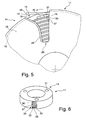
- FIG. 5 is schematically enlarged, the insertion opening 28 is shown.
- This insertion opening 28 extends not only radially along the receiving space 16, as in FIG. 5
- the radially outer region of the outlet opening 28 is formed wider than the radially inner region.
- the increasing opening width can, as shown in the embodiment, be provided by a discontinuous course or else include a continuous curved course.
- the receiving space 16 preferably has at the outermost end of the groove on a starting portion 46, which extends from the groove bottom continuously up to the height of the web 37. The web 37 then continues in a helical manner to form the receiving space 16.
- a free end 48 of the winding material 15 extends due to the residual stress from the insertion opening 28 radially outward.
- the winding material 15 is led out of the receiving space 16 along the insertion bevel 29.
- an outer winding is removed from the receiving space 16. This outer winding is located in a space formed between the web 37 and a lateral surface 19 of the housing part 18. After this turn is completely removed, the winding material 15 follows along the initial section 46, which rises steadily, so that a secured winding material execution is ensured in the transition from a free space between the web 37 and the lateral surface 19 in a space between two adjacent webs 37.
- FIG. 2 shows a perspective view of an alternative embodiment of the device 11.
- This alternative embodiment of the device 11 differs from the previously described embodiment in that the receiving space 16 is aligned axially with respect to the axis of rotation 17 of the winding material receptacle 12 and of the housing part 14 of the device 11.
- the advantages and modes of operation of this alternative embodiment according to FIG. 6 is analogous to the previously described embodiment.
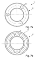
- the FIGS. 7a and 7b show a view on the top and bottom of the alternative embodiments according to FIG. 6 ,
- the winding material receiving 12 is formed for example as a ring, for example, has a U-shaped cross section, as in a solid cross-section in FIG. 8 is shown.
- the winding material guide 33 in particular the profiled surface 34 is provided.
- a circumferential recess 42 is provided, into which engages at least one locking element 23 which is positioned on the housing part 14.
- the recess 42 and the at least one latching element 23 form the releasable latching connection 22 by way of example.
- the latching element 23 can also be designed as a radially encircling elevation. Alternatively, the increase may extend only in sections over the circumference. By means of a simple clip connection, latching of the housing part 14 to the winding material receptacle 12 can take place. Such an arrangement can also be dismantled in a simple manner.
- the inlet opening 28 is provided on an outer circumferential surface 19 of the housing part 14 and extends in the axial direction in the lateral surface 19.
- the width of the inlet opening 28 is such that upon rotation of the housing part 12, 14 takes an independent Ausädeln due to the inherent clamping force.
- the inlet opening 28 may have an extended opening portion, which may represent, for example, a Ausfädel Anlagen to more easily take out one end of the winding material 15 from the wound position in the receiving space 16 due to its inherent rigidity.
- the Wickelguting 12 includes, for example according to Figure 7a and Figure 7b two gripping surfaces formed as recessed grips 31, which interrupt the U-shaped cross-section. As an alternative to such recessed grips, it is also possible to provide constrictions of the U-shaped cross section. In the Figure 7a and Figure 7b The arrangement shown has the advantage that a very light weight device 11 is created.
- cams 39 in particular semicircular cams, provided, as for example in FIG. 9 is shown.
- These semicircular cams 39 extend transversely to the profiled, in particular grooved, surface 34, which has a continuous groove 36 in the form of having a screw thread.
- Such semicircular cams 39 are uniformly provided at a distance from the inner periphery of the lateral surface 19 of the housing part 14.
- an opening or a connection can be provided on the lateral surface 19 of the housing part 14 in order to flush the receiving space 16.
- a so-called Luer connection is provided.
- a rinsing and cleaning of the receiving space can be made possible in the wound state of the winding material 15.
- Such a luer lock can also in the embodiments according to the FIGS. 1 to 5 be provided.
- FIG. 6 illustrated embodiment of the dispenser 11 is preferably formed only in two parts, in particular, the winding material 12 and the housing part 14 are formed as an injection molded part.
- FIG. 10 is a perspective view of a device 51 for winding an elastically deformable winding material 15 shown, through which the winding material 15 can be wound into the device 11.
- This device 11 for automatic winding in particular of flexible endoscopic instruments, such as guide wires, catheter, slings, biopsy forceps or the like, comprises a housing 52 in which a drive device, not shown, is provided.
- This drive device comprises a controller and a motor, in particular a servomotor.
- This servomotor drives a rotating device 54 which, for example, comprises a turntable 55, which is preferably part of a receiving recess 56 which adjoins an upper side of the housing 52.
- the turntable 55 is integrated in the receiving recess 56 such that preferably a closed housing surface is provided.
- the receiving recess 56 is preferably adapted to the outer contour of the device 11.
- a recess 57 may be provided for receiving the retaining tab 20.
- the device 11 is inserted into the receiving recess 56.
- drivers 58 which protrude upwards relative to the turntable 55, preferably engage in gripping surfaces 31 or depressions of the winding receptacle 12.
- the housing part 14 is provided, for example via the retaining tab 20 secured against rotation in the receiving recess 56.
- Locks 68 for example, project laterally into the receiving recess 56, fix the device 11 in the receiving recess 56.
- the device 51 is switched on and off via a switch 60. Via a potentiometer 61, for example, the winding speed can be adjusted.
- the winding duration can be set as a function of the length of the winding material 15 to be wound up.
- a display 63 various information can be output to the user, such as that the device 51 is ready to start a winding process or that the winding process is now completed.
- the winding process is started after inserting the device 11 into the device 51, for example by a button 65, which is preferably designed as a foot switch. Also, a start and stop button may be provided on the housing 52.
- a slow start-up of the turntable 55 preferably takes place a slow start-up of the turntable 55, so that, for example, a one or a half times, but also a two- or three-fold slower or slow increasing speed to ensure that the beginning of the winding material 15 is received and retracted becomes.
- a plurality of turns can be wound with high drive speed depending on the length of the winding material 15.
- the last turn is driven again with a reducing winding speed.
- a servo motor is preferably provided, which can drive a rotary axis of the turntable 15 directly.
- switched between a gear can be provided.
- belt drives or other drives can be used to preferably achieve a flat-building compact housing 52 of the device 51.
- the controller By adjusting the winding length via the potentiometer 62, it can be made possible, for example, that at the beginning of the winding process, the button 65 is pressed and then an automatic and complete winding takes place, without further actuation of switches or buttons is required. After the rotator 54 makes the required number of revolutions, the controller recognizes that the winding operation has been completed and stops the rotator 54.
- the winding material 15 can be aligned by an operator to the insertion opening 28.
- a feeding device is provided, which leads the winding material 15.
- the feed moves radially outward, so that the supply of the winding material 15 is always positioned according to the next following groove 36 of the winding receptacle 15. It can also be done at the same time a cleaning of the winding material 15.
- the device 51 preferably has an optical signal transmitter 67 which, for example, directs a laser light onto the insertion opening 28 of the receiving space 16 of the device 11.
- the insertion of the winding material 15 can be specified for winding the winding material 15.
- the winding start is provided on a radial inner side of the insertion opening 28.
- the starting point is in the central region of the insertion opening 28. This position can be accurately displayed by the laser light.
- the device 11 is taken out of the receiving recess 56.
- one or more recessed grips adjoin the recess 57 or receiving recess 56 in order to remove the device 11.
- Such recesses are provided adjacent releasable detents 68, which radially, preferably evenly distributed over the circumference, are provided on the receiving recess 56 to hold down the device 11 during the winding process.
- Such detents 18 may be formed as spring-loaded locking elements or the like, which act on the housing part 14 to secure the winding position.
- ejector elements may be provided which can be controlled via the button 65 or via a separate switch.
- Such ejector elements may preferably be integrated in the drivers 58 or be formed by the drivers 58. These are moved to eject the device 11 upwards, so that then the device 11 is released from the detents 68 and can be removed. Likewise, separately incorporated in the turntable 55 or the receiving recess 56 such Auswerferieri be provided.
- receiving recess 56 is arranged spaced from the respective side edges of the housing 52.
- This device 51 is particularly for winding a device according to the FIGS. 1 to 5 intended.
- another receptacle may be provided which has the same functions as the receiving recess 56 and the rotating device 54.
- this arrangement may also be provided elevated relative to a housing surface, in which case the corresponding provisions are to be provided in order to form an anti-twist device and to suppress the device 11 to the rotating device 54.
- This device 51 is also suitable in principle for the winding of the alternative embodiment of the device 11 according to the FIGS. 6 to 9 , It can be provided that the receiving recess 56 is adjacent to a side wall of the housing 52, so that the front-side insertion opening 28 of the device 11 according to the FIGS. 6 to 9 is accessible.
- a type of cage may be provided which extends upwardly with respect to the rotator 54 to engage the housing member 14, this cage having at least one lateral opening to allow the lateral insertion opening 28 of the device 11, like this FIG. 6 shows, for the winding material 15 is accessible. All other features and functions of the device 51 are for the embodiment of the device according to the FIGS. 6 to 9 the same as for the embodiment according to the FIGS. 1 to 5 ,
Landscapes
- Storing, Repeated Paying-Out, And Re-Storing Of Elongated Articles (AREA)
- Media Introduction/Drainage Providing Device (AREA)
- Endoscopes (AREA)
Applications Claiming Priority (1)
| Application Number | Priority Date | Filing Date | Title |
|---|---|---|---|
| DE102008022666A DE102008022666A1 (de) | 2008-05-07 | 2008-05-07 | Drahtdipenser zur Aufnahme eines elastisch verformbaren Drahtes |
Publications (3)
| Publication Number | Publication Date |
|---|---|
| EP2116497A2 true EP2116497A2 (fr) | 2009-11-11 |
| EP2116497A3 EP2116497A3 (fr) | 2010-03-17 |
| EP2116497B1 EP2116497B1 (fr) | 2016-02-10 |
Family
ID=41066084
Family Applications (1)
| Application Number | Title | Priority Date | Filing Date |
|---|---|---|---|
| EP09005979.1A Not-in-force EP2116497B1 (fr) | 2008-05-07 | 2009-04-30 | Dispositif de réception d'un fil de guidage médical flexible |
Country Status (3)
| Country | Link |
|---|---|
| US (1) | US8651412B2 (fr) |
| EP (1) | EP2116497B1 (fr) |
| DE (1) | DE102008022666A1 (fr) |
Cited By (2)
| Publication number | Priority date | Publication date | Assignee | Title |
|---|---|---|---|---|
| CN103523560A (zh) * | 2013-10-22 | 2014-01-22 | 台州迈得医疗工业设备股份有限公司 | 一种医用导管卷绕装置 |
| CN119306076A (zh) * | 2024-12-19 | 2025-01-14 | 中国人民解放军西部战区总医院 | 一种导丝收纳器 |
Families Citing this family (10)
| Publication number | Priority date | Publication date | Assignee | Title |
|---|---|---|---|---|
| CN102655905B (zh) * | 2009-12-21 | 2015-04-29 | 科洛普拉斯特公司 | 一种导尿管套件 |
| JP2011219271A (ja) * | 2010-03-25 | 2011-11-04 | Seiko Epson Corp | 記録装置 |
| US20120091249A1 (en) * | 2010-10-19 | 2012-04-19 | John Mezzalingua Associates, Inc. | Cable carrying case |
| US10265499B2 (en) * | 2011-05-31 | 2019-04-23 | Compactcath, Inc. | Compact urinary catheter |
| US8556884B2 (en) | 2011-05-31 | 2013-10-15 | Compactcath, Inc. | Compact catheter assembly |
| CN104056339B (zh) * | 2013-03-21 | 2016-02-10 | 山东威高集团医用高分子制品股份有限公司 | 一种导丝推送器 |
| US12226595B2 (en) * | 2018-04-20 | 2025-02-18 | Becton, Dickinson And Company | Instrument delivery device having a rotary element |
| CN108557560B (zh) * | 2018-04-28 | 2024-03-22 | 上海英诺伟医疗器械股份有限公司 | 一种自动盘管机 |
| US12054354B2 (en) | 2021-04-05 | 2024-08-06 | Justin Rowley | Motorized reel apparatus for needle biopsy operations |
| US12409303B2 (en) * | 2021-12-10 | 2025-09-09 | Wisconsin Alumni Research Foundation | Wire and catheter organizer for endovascular procedure |
Citations (5)
| Publication number | Priority date | Publication date | Assignee | Title |
|---|---|---|---|---|
| EP0050606A1 (fr) | 1980-10-22 | 1982-04-28 | Bengt Gustavsson | Conteneur distributeur pour cathéter veineux |
| DE19751194C1 (de) | 1997-11-19 | 1999-05-06 | Epflex Feinwerktech Gmbh | Drahtdispenser für elastische Drähte |
| US6086008A (en) | 1997-12-22 | 2000-07-11 | Deka Products Limited Partnership | Apparatus and method for permitting introduction and withdrawal of a catheter |
| WO2007081264A1 (fr) | 2006-01-10 | 2007-07-19 | Cimatex Ab | Réceptacle pour cathéter |
| EP2215703A2 (fr) | 2007-11-22 | 2010-08-11 | Robert Bosch GmbH | Machine à courant continu |
Family Cites Families (18)
| Publication number | Priority date | Publication date | Assignee | Title |
|---|---|---|---|---|
| DE7330339U (de) * | 1974-01-10 | Siemens Ag | Aufwickelvorrichtung für elektrische Kabel von medizinischen Geräten | |
| DE705802C (de) | 1938-06-09 | 1941-05-10 | Ref Weygandt & Klein G M B H | Schlauchhaspel, insbesondere fuer Brennstofftankschlaeuche |
| US2711734A (en) | 1954-02-01 | 1955-06-28 | Oliver M Moe | Surgical instrument |
| DE2845629C2 (de) | 1977-10-20 | 1982-04-22 | Olympus Optical Co., Ltd., Tokyo | Kassetten-Wendevorrichtung für ein mit einer Bandkassette betreibbares Tonbandgerät |
| US4917094A (en) * | 1987-10-28 | 1990-04-17 | Medical Parameters Inc. | Guidewire advancement system |
| US4860757A (en) * | 1987-10-28 | 1989-08-29 | Medical Parameters, Incorporated | Guidewire advancement system |
| US5273042A (en) * | 1987-10-28 | 1993-12-28 | Medical Parameters, Inc. | Guidewire advancement method |
| GB8802935D0 (en) | 1988-02-09 | 1988-03-09 | Ems Medical Group Ltd | Dispenser for surgical guidewire |
| US5344011A (en) * | 1993-02-12 | 1994-09-06 | Advanced Cardiovascular Systems, Inc. | Packaging system for an elongated flexible product |
| US5366444A (en) * | 1993-07-06 | 1994-11-22 | Med-Pro Design, Inc. | Hand operated guide wire advancement device |
| JP2601155Y2 (ja) * | 1993-10-06 | 1999-11-08 | 日本シャーウッド株式会社 | ガイドワイヤー挿入補助具 |
| US6231564B1 (en) | 1995-09-29 | 2001-05-15 | Medtronic Ave, Inc. | Storable guidewire system |
| US5827202A (en) * | 1996-06-10 | 1998-10-27 | Baxter International Inc. | Guide wire dispenser apparatus and method |
| US7520382B2 (en) * | 2003-07-18 | 2009-04-21 | Tyco Healthcare Group Lp | Suture packaging |
| DE102005013742A1 (de) * | 2004-10-29 | 2006-05-04 | Dura Automotive Systems Gmbh | Gerät zum synchronen Aus- und Einfahren von zwei Drahtabschnitten |
| US7116883B2 (en) * | 2004-11-19 | 2006-10-03 | Fiber Optic Protection Systems, Inc. | Fiber optic protective carrier |
| US20060264921A1 (en) * | 2004-12-29 | 2006-11-23 | Imflux Llc | Retractable Surgical Instruments |
| US8256613B2 (en) * | 2008-04-07 | 2012-09-04 | Tyco Healthcare Group Lp | Suture packaging for barbed sutures |
-
2008
- 2008-05-07 DE DE102008022666A patent/DE102008022666A1/de not_active Ceased
-
2009
- 2009-04-30 US US12/387,282 patent/US8651412B2/en not_active Expired - Fee Related
- 2009-04-30 EP EP09005979.1A patent/EP2116497B1/fr not_active Not-in-force
Patent Citations (5)
| Publication number | Priority date | Publication date | Assignee | Title |
|---|---|---|---|---|
| EP0050606A1 (fr) | 1980-10-22 | 1982-04-28 | Bengt Gustavsson | Conteneur distributeur pour cathéter veineux |
| DE19751194C1 (de) | 1997-11-19 | 1999-05-06 | Epflex Feinwerktech Gmbh | Drahtdispenser für elastische Drähte |
| US6086008A (en) | 1997-12-22 | 2000-07-11 | Deka Products Limited Partnership | Apparatus and method for permitting introduction and withdrawal of a catheter |
| WO2007081264A1 (fr) | 2006-01-10 | 2007-07-19 | Cimatex Ab | Réceptacle pour cathéter |
| EP2215703A2 (fr) | 2007-11-22 | 2010-08-11 | Robert Bosch GmbH | Machine à courant continu |
Cited By (3)
| Publication number | Priority date | Publication date | Assignee | Title |
|---|---|---|---|---|
| CN103523560A (zh) * | 2013-10-22 | 2014-01-22 | 台州迈得医疗工业设备股份有限公司 | 一种医用导管卷绕装置 |
| CN103523560B (zh) * | 2013-10-22 | 2015-09-30 | 迈得医疗工业设备股份有限公司 | 一种医用导管卷绕装置 |
| CN119306076A (zh) * | 2024-12-19 | 2025-01-14 | 中国人民解放军西部战区总医院 | 一种导丝收纳器 |
Also Published As
| Publication number | Publication date |
|---|---|
| US8651412B2 (en) | 2014-02-18 |
| EP2116497B1 (fr) | 2016-02-10 |
| US20090277988A1 (en) | 2009-11-12 |
| EP2116497A3 (fr) | 2010-03-17 |
| DE102008022666A1 (de) | 2009-12-03 |
Similar Documents
| Publication | Publication Date | Title |
|---|---|---|
| EP2116497A2 (fr) | Dispositif de réception d'un matériau d'enroulement élastique déformable et dispositif d'enroulement du matériau d'enroulement dans le dispositif | |
| DE102011010442B4 (de) | Gewindekernausschraubvorrichtung | |
| DE4334811A1 (de) | Positionserfassungsvorrichtung an einem Linearantrieb | |
| DE102007053044B3 (de) | Gewindekernausschraubvorrichtung für Spritzgiesswerkzeuge | |
| DE102009000891A1 (de) | Verfahren zur Ausformung eines Innengewindes an einem Grundkörper | |
| CH649407A5 (de) | Aufzeichnungseinrichtung und kassette fuer eine solche aufzeichnungseinrichtung. | |
| DE3738678A1 (de) | Fluessigkeitsapplikator, beispielsweise kosmetikinstrument, schreibgeraet und dergl. | |
| DE1928954A1 (de) | Bohrfutter | |
| DE3515223A1 (de) | Vorrichtung zum abisolieren von lackisolierten runddraehten | |
| DE1956936B2 (de) | Maschine zur halbkontinuierlichen Herstellung von Wendelhohlleitern großer Länge | |
| DE102004006930A1 (de) | Werkzeug zur Erweiterung eines in einem Knochen ausgebildeten Loches, insbesondere zum Einsetzen eines intraossären Zahnimplantates | |
| DE10309446A1 (de) | Verfahren zum Herstellen eines Türgriffs für Fahrzeuge | |
| DE1435533A1 (de) | Garnspindel,insbesondere zur aufnahme von Abfallgarn | |
| DE102011121084A1 (de) | Gewindekernausschraubvorrichtung | |
| DE202008014781U1 (de) | Wickelmaschine zur gleichzeitigen Wicklung mehrerer Spulen | |
| EP2223752B1 (fr) | Kit de construction des outils destinés à former des outils de cintrage pouvant être couplés sur une unité d'outils d'une machine de cintrage ou de l'enroulement de pièces en forme de tronçons | |
| DE102008056767A1 (de) | Verfahren und Vorrichtung zum Aufwickeln einer Fadenspule | |
| DE2362485A1 (de) | Spule fuer eine maschine zur umhuellung von kabeln | |
| DE102008015629A1 (de) | Vorrichtung zum Abbinden und Isolieren von elektrischen Leitern und/oder Bündeln von elektrischen Leitern | |
| DE2038654C3 (de) | An einer Spinnspindel befestigter Konus für Abfallgarn | |
| DE102011121085A1 (de) | Gewindekernausschraubvorrichtung | |
| DE1302431B (fr) | ||
| DE102024121499A1 (de) | Lenkergriff | |
| DE19630324A1 (de) | Chirurgisches Instrument | |
| DE19821337C2 (de) | Handwerkzeugmaschine mit vereinfachtem Werkzeugwechsel |
Legal Events
| Date | Code | Title | Description |
|---|---|---|---|
| PUAI | Public reference made under article 153(3) epc to a published international application that has entered the european phase |
Free format text: ORIGINAL CODE: 0009012 |
|
| AK | Designated contracting states |
Kind code of ref document: A2 Designated state(s): AT BE BG CH CY CZ DE DK EE ES FI FR GB GR HR HU IE IS IT LI LT LU LV MC MK MT NL NO PL PT RO SE SI SK TR |
|
| PUAL | Search report despatched |
Free format text: ORIGINAL CODE: 0009013 |
|
| AK | Designated contracting states |
Kind code of ref document: A3 Designated state(s): AT BE BG CH CY CZ DE DK EE ES FI FR GB GR HR HU IE IS IT LI LT LU LV MC MK MT NL NO PL PT RO SE SI SK TR |
|
| AX | Request for extension of the european patent |
Extension state: AL BA RS |
|
| 17P | Request for examination filed |
Effective date: 20100917 |
|
| 17Q | First examination report despatched |
Effective date: 20101111 |
|
| REG | Reference to a national code |
Ref country code: DE Ref legal event code: R079 Ref document number: 502009012108 Country of ref document: DE Free format text: PREVIOUS MAIN CLASS: B65H0075440000 Ipc: A61M0025000000 |
|
| RIC1 | Information provided on ipc code assigned before grant |
Ipc: A61M 25/00 20060101AFI20150528BHEP Ipc: B65H 75/44 20060101ALI20150528BHEP |
|
| GRAP | Despatch of communication of intention to grant a patent |
Free format text: ORIGINAL CODE: EPIDOSNIGR1 |
|
| INTG | Intention to grant announced |
Effective date: 20150715 |
|
| GRAS | Grant fee paid |
Free format text: ORIGINAL CODE: EPIDOSNIGR3 |
|
| INTG | Intention to grant announced |
Effective date: 20151203 |
|
| GRAA | (expected) grant |
Free format text: ORIGINAL CODE: 0009210 |
|
| AK | Designated contracting states |
Kind code of ref document: B1 Designated state(s): AT BE BG CH CY CZ DE DK EE ES FI FR GB GR HR HU IE IS IT LI LT LU LV MC MK MT NL NO PL PT RO SE SI SK TR |
|
| REG | Reference to a national code |
Ref country code: GB Ref legal event code: FG4D Free format text: NOT ENGLISH |
|
| REG | Reference to a national code |
Ref country code: AT Ref legal event code: REF Ref document number: 774344 Country of ref document: AT Kind code of ref document: T Effective date: 20160215 Ref country code: CH Ref legal event code: EP |
|
| REG | Reference to a national code |
Ref country code: IE Ref legal event code: FG4D Free format text: LANGUAGE OF EP DOCUMENT: GERMAN |
|
| REG | Reference to a national code |
Ref country code: DE Ref legal event code: R096 Ref document number: 502009012108 Country of ref document: DE |
|
| REG | Reference to a national code |
Ref country code: FR Ref legal event code: PLFP Year of fee payment: 8 |
|
| REG | Reference to a national code |
Ref country code: LT Ref legal event code: MG4D |
|
| REG | Reference to a national code |
Ref country code: NL Ref legal event code: MP Effective date: 20160210 |
|
| PG25 | Lapsed in a contracting state [announced via postgrant information from national office to epo] |
Ref country code: HR Free format text: LAPSE BECAUSE OF FAILURE TO SUBMIT A TRANSLATION OF THE DESCRIPTION OR TO PAY THE FEE WITHIN THE PRESCRIBED TIME-LIMIT Effective date: 20160210 Ref country code: GR Free format text: LAPSE BECAUSE OF FAILURE TO SUBMIT A TRANSLATION OF THE DESCRIPTION OR TO PAY THE FEE WITHIN THE PRESCRIBED TIME-LIMIT Effective date: 20160511 Ref country code: ES Free format text: LAPSE BECAUSE OF FAILURE TO SUBMIT A TRANSLATION OF THE DESCRIPTION OR TO PAY THE FEE WITHIN THE PRESCRIBED TIME-LIMIT Effective date: 20160210 Ref country code: NO Free format text: LAPSE BECAUSE OF FAILURE TO SUBMIT A TRANSLATION OF THE DESCRIPTION OR TO PAY THE FEE WITHIN THE PRESCRIBED TIME-LIMIT Effective date: 20160510 Ref country code: IT Free format text: LAPSE BECAUSE OF FAILURE TO SUBMIT A TRANSLATION OF THE DESCRIPTION OR TO PAY THE FEE WITHIN THE PRESCRIBED TIME-LIMIT Effective date: 20160210 Ref country code: FI Free format text: LAPSE BECAUSE OF FAILURE TO SUBMIT A TRANSLATION OF THE DESCRIPTION OR TO PAY THE FEE WITHIN THE PRESCRIBED TIME-LIMIT Effective date: 20160210 |
|
| PG25 | Lapsed in a contracting state [announced via postgrant information from national office to epo] |
Ref country code: NL Free format text: LAPSE BECAUSE OF FAILURE TO SUBMIT A TRANSLATION OF THE DESCRIPTION OR TO PAY THE FEE WITHIN THE PRESCRIBED TIME-LIMIT Effective date: 20160210 Ref country code: BE Free format text: LAPSE BECAUSE OF NON-PAYMENT OF DUE FEES Effective date: 20160430 Ref country code: IS Free format text: LAPSE BECAUSE OF FAILURE TO SUBMIT A TRANSLATION OF THE DESCRIPTION OR TO PAY THE FEE WITHIN THE PRESCRIBED TIME-LIMIT Effective date: 20160610 Ref country code: LT Free format text: LAPSE BECAUSE OF FAILURE TO SUBMIT A TRANSLATION OF THE DESCRIPTION OR TO PAY THE FEE WITHIN THE PRESCRIBED TIME-LIMIT Effective date: 20160210 Ref country code: PT Free format text: LAPSE BECAUSE OF FAILURE TO SUBMIT A TRANSLATION OF THE DESCRIPTION OR TO PAY THE FEE WITHIN THE PRESCRIBED TIME-LIMIT Effective date: 20160613 Ref country code: SE Free format text: LAPSE BECAUSE OF FAILURE TO SUBMIT A TRANSLATION OF THE DESCRIPTION OR TO PAY THE FEE WITHIN THE PRESCRIBED TIME-LIMIT Effective date: 20160210 Ref country code: LV Free format text: LAPSE BECAUSE OF FAILURE TO SUBMIT A TRANSLATION OF THE DESCRIPTION OR TO PAY THE FEE WITHIN THE PRESCRIBED TIME-LIMIT Effective date: 20160210 Ref country code: PL Free format text: LAPSE BECAUSE OF FAILURE TO SUBMIT A TRANSLATION OF THE DESCRIPTION OR TO PAY THE FEE WITHIN THE PRESCRIBED TIME-LIMIT Effective date: 20160210 |
|
| PG25 | Lapsed in a contracting state [announced via postgrant information from national office to epo] |
Ref country code: DK Free format text: LAPSE BECAUSE OF FAILURE TO SUBMIT A TRANSLATION OF THE DESCRIPTION OR TO PAY THE FEE WITHIN THE PRESCRIBED TIME-LIMIT Effective date: 20160210 Ref country code: EE Free format text: LAPSE BECAUSE OF FAILURE TO SUBMIT A TRANSLATION OF THE DESCRIPTION OR TO PAY THE FEE WITHIN THE PRESCRIBED TIME-LIMIT Effective date: 20160210 |
|
| REG | Reference to a national code |
Ref country code: DE Ref legal event code: R097 Ref document number: 502009012108 Country of ref document: DE |
|
| PG25 | Lapsed in a contracting state [announced via postgrant information from national office to epo] |
Ref country code: SK Free format text: LAPSE BECAUSE OF FAILURE TO SUBMIT A TRANSLATION OF THE DESCRIPTION OR TO PAY THE FEE WITHIN THE PRESCRIBED TIME-LIMIT Effective date: 20160210 Ref country code: RO Free format text: LAPSE BECAUSE OF FAILURE TO SUBMIT A TRANSLATION OF THE DESCRIPTION OR TO PAY THE FEE WITHIN THE PRESCRIBED TIME-LIMIT Effective date: 20160210 Ref country code: CZ Free format text: LAPSE BECAUSE OF FAILURE TO SUBMIT A TRANSLATION OF THE DESCRIPTION OR TO PAY THE FEE WITHIN THE PRESCRIBED TIME-LIMIT Effective date: 20160210 |
|
| REG | Reference to a national code |
Ref country code: CH Ref legal event code: PL |
|
| PLBE | No opposition filed within time limit |
Free format text: ORIGINAL CODE: 0009261 |
|
| STAA | Information on the status of an ep patent application or granted ep patent |
Free format text: STATUS: NO OPPOSITION FILED WITHIN TIME LIMIT |
|
| PG25 | Lapsed in a contracting state [announced via postgrant information from national office to epo] |
Ref country code: LU Free format text: LAPSE BECAUSE OF FAILURE TO SUBMIT A TRANSLATION OF THE DESCRIPTION OR TO PAY THE FEE WITHIN THE PRESCRIBED TIME-LIMIT Effective date: 20160430 |
|
| 26N | No opposition filed |
Effective date: 20161111 |
|
| REG | Reference to a national code |
Ref country code: IE Ref legal event code: MM4A |
|
| PG25 | Lapsed in a contracting state [announced via postgrant information from national office to epo] |
Ref country code: CH Free format text: LAPSE BECAUSE OF NON-PAYMENT OF DUE FEES Effective date: 20160430 Ref country code: LI Free format text: LAPSE BECAUSE OF NON-PAYMENT OF DUE FEES Effective date: 20160430 |
|
| PG25 | Lapsed in a contracting state [announced via postgrant information from national office to epo] |
Ref country code: BG Free format text: LAPSE BECAUSE OF FAILURE TO SUBMIT A TRANSLATION OF THE DESCRIPTION OR TO PAY THE FEE WITHIN THE PRESCRIBED TIME-LIMIT Effective date: 20160510 Ref country code: SI Free format text: LAPSE BECAUSE OF FAILURE TO SUBMIT A TRANSLATION OF THE DESCRIPTION OR TO PAY THE FEE WITHIN THE PRESCRIBED TIME-LIMIT Effective date: 20160210 |
|
| REG | Reference to a national code |
Ref country code: FR Ref legal event code: PLFP Year of fee payment: 9 |
|
| PG25 | Lapsed in a contracting state [announced via postgrant information from national office to epo] |
Ref country code: IE Free format text: LAPSE BECAUSE OF NON-PAYMENT OF DUE FEES Effective date: 20160430 |
|
| REG | Reference to a national code |
Ref country code: AT Ref legal event code: MM01 Ref document number: 774344 Country of ref document: AT Kind code of ref document: T Effective date: 20160430 |
|
| PG25 | Lapsed in a contracting state [announced via postgrant information from national office to epo] |
Ref country code: AT Free format text: LAPSE BECAUSE OF NON-PAYMENT OF DUE FEES Effective date: 20160430 |
|
| REG | Reference to a national code |
Ref country code: FR Ref legal event code: PLFP Year of fee payment: 10 |
|
| PG25 | Lapsed in a contracting state [announced via postgrant information from national office to epo] |
Ref country code: CY Free format text: LAPSE BECAUSE OF FAILURE TO SUBMIT A TRANSLATION OF THE DESCRIPTION OR TO PAY THE FEE WITHIN THE PRESCRIBED TIME-LIMIT Effective date: 20160210 Ref country code: HU Free format text: LAPSE BECAUSE OF FAILURE TO SUBMIT A TRANSLATION OF THE DESCRIPTION OR TO PAY THE FEE WITHIN THE PRESCRIBED TIME-LIMIT; INVALID AB INITIO Effective date: 20090430 |
|
| PG25 | Lapsed in a contracting state [announced via postgrant information from national office to epo] |
Ref country code: TR Free format text: LAPSE BECAUSE OF FAILURE TO SUBMIT A TRANSLATION OF THE DESCRIPTION OR TO PAY THE FEE WITHIN THE PRESCRIBED TIME-LIMIT Effective date: 20160210 Ref country code: MK Free format text: LAPSE BECAUSE OF FAILURE TO SUBMIT A TRANSLATION OF THE DESCRIPTION OR TO PAY THE FEE WITHIN THE PRESCRIBED TIME-LIMIT Effective date: 20160210 Ref country code: MT Free format text: LAPSE BECAUSE OF FAILURE TO SUBMIT A TRANSLATION OF THE DESCRIPTION OR TO PAY THE FEE WITHIN THE PRESCRIBED TIME-LIMIT Effective date: 20160210 Ref country code: MC Free format text: LAPSE BECAUSE OF FAILURE TO SUBMIT A TRANSLATION OF THE DESCRIPTION OR TO PAY THE FEE WITHIN THE PRESCRIBED TIME-LIMIT Effective date: 20160210 |
|
| PGFP | Annual fee paid to national office [announced via postgrant information from national office to epo] |
Ref country code: FR Payment date: 20180424 Year of fee payment: 10 |
|
| PGFP | Annual fee paid to national office [announced via postgrant information from national office to epo] |
Ref country code: GB Payment date: 20180424 Year of fee payment: 10 |
|
| GBPC | Gb: european patent ceased through non-payment of renewal fee |
Effective date: 20190430 |
|
| PG25 | Lapsed in a contracting state [announced via postgrant information from national office to epo] |
Ref country code: GB Free format text: LAPSE BECAUSE OF NON-PAYMENT OF DUE FEES Effective date: 20190430 |
|
| PG25 | Lapsed in a contracting state [announced via postgrant information from national office to epo] |
Ref country code: FR Free format text: LAPSE BECAUSE OF NON-PAYMENT OF DUE FEES Effective date: 20190430 |
|
| PGFP | Annual fee paid to national office [announced via postgrant information from national office to epo] |
Ref country code: DE Payment date: 20200424 Year of fee payment: 12 |
|
| REG | Reference to a national code |
Ref country code: DE Ref legal event code: R119 Ref document number: 502009012108 Country of ref document: DE |
|
| PG25 | Lapsed in a contracting state [announced via postgrant information from national office to epo] |
Ref country code: DE Free format text: LAPSE BECAUSE OF NON-PAYMENT OF DUE FEES Effective date: 20211103 |