EP2116643B1 - Verfahren zur nadelselektion und flachstrickmaschine - Google Patents
Verfahren zur nadelselektion und flachstrickmaschine Download PDFInfo
- Publication number
- EP2116643B1 EP2116643B1 EP07849879.7A EP07849879A EP2116643B1 EP 2116643 B1 EP2116643 B1 EP 2116643B1 EP 07849879 A EP07849879 A EP 07849879A EP 2116643 B1 EP2116643 B1 EP 2116643B1
- Authority
- EP
- European Patent Office
- Prior art keywords
- needle
- carriage
- knitting
- cam
- preliminary
- Prior art date
- Legal status (The legal status is an assumption and is not a legal conclusion. Google has not performed a legal analysis and makes no representation as to the accuracy of the status listed.)
- Not-in-force
Links
Images


Classifications
-
- D—TEXTILES; PAPER
- D04—BRAIDING; LACE-MAKING; KNITTING; TRIMMINGS; NON-WOVEN FABRICS
- D04B—KNITTING
- D04B15/00—Details of, or auxiliary devices incorporated in, weft knitting machines, restricted to machines of this kind
- D04B15/94—Driving-gear not otherwise provided for
- D04B15/96—Driving-gear not otherwise provided for in flat-bed knitting machines
-
- D—TEXTILES; PAPER
- D04—BRAIDING; LACE-MAKING; KNITTING; TRIMMINGS; NON-WOVEN FABRICS
- D04B—KNITTING
- D04B15/00—Details of, or auxiliary devices incorporated in, weft knitting machines, restricted to machines of this kind
- D04B15/32—Cam systems or assemblies for operating knitting instruments
- D04B15/36—Cam systems or assemblies for operating knitting instruments for flat-bed knitting machines
- D04B15/362—Cam systems or assemblies for operating knitting instruments for flat-bed knitting machines with two needle beds in V-formation
- D04B15/365—Cam systems or assemblies for operating knitting instruments for flat-bed knitting machines with two needle beds in V-formation with provision for loop transfer from one needle bed to the other
-
- D—TEXTILES; PAPER
- D04—BRAIDING; LACE-MAKING; KNITTING; TRIMMINGS; NON-WOVEN FABRICS
- D04B—KNITTING
- D04B15/00—Details of, or auxiliary devices incorporated in, weft knitting machines, restricted to machines of this kind
- D04B15/66—Devices for determining or controlling patterns ; Program-control arrangements
- D04B15/68—Devices for determining or controlling patterns ; Program-control arrangements characterised by the knitting instruments used
- D04B15/70—Devices for determining or controlling patterns ; Program-control arrangements characterised by the knitting instruments used in flat-bed knitting machines
Definitions
- the present invention relates to a method for selecting needles in two steps by the use of needle selecting mechanisms disposed on both sides of each cam system in a flatbed knitting machine provided with a carriage in which plural sets of cam systems are mounted, and to a flatbed knitting machine that executes such method of selecting needles.
- knitting needles in a flatbed knitting machine, with a large number of knitting needles disposed on a needle bed, needle selection and knitting drive are conducted by a needle selecting mechanism and a cam system mounted to a carriage that runs along the needle bed in order to knit the fabric.
- the knitting operation of knitting needles basically consists of three types, knit, tuck, and miss.
- a hook at a front end of a knitting needle is advanced to a needle bed gap, receives a knitting yarn fed in the gap and forms a new knitted loop, while a knitted loop held till then is cleared from the hook.
- tuck the hook is advanced to the needle bed gap to an extent that the knitted loop held till then is not cleared, while a new knitted loop is formed.
- Fig. 6 shows basic structure of a flatbed knitting machine 1 that knits the fabric.
- the flatbed knitting machine 1 is equipped with needle beds 2 extending in the horizontal direction.
- the needle bed 2 has a large number of needle grooves oriented in the direction perpendicular to the extended longitudinal direction, though the illustration is omitted.
- a knitting needle is housed in each needle groove, and the knitting needles are driven by cam systems 4a and 4b mounted to a carriage 3 running back and forth along the needle bed 2 and carry out knitting operations.
- cam systems 4a and 4b needle selecting mechanisms 5a and 6a; 5b and 6b are disposed on both sides in the running direction, respectively.
- Each needle selecting mechanism 5a and 6a; 5b and 6b can divide knitting needles into two groups with different states.
- the needle selecting states by the needle selecting mechanisms 5a and 6a; 5b and 6b can be reset to a reference state by resetting mechanisms 7a and 7b provided to each cam system 4a and 4b.
- needles for knitting the fabric by the cam system 4a on the trailing side in the running direction are selected in two steps, in which the needle selecting mechanism 5b behind the cam system 4b and the needle selecting mechanism 6a in front of the cam system 4a are used.
- the cam system 4b on the leading side in the running direction carries out the knitting operations taking along a yarn feeder 8
- needles are selected only in one step by the use of the front needle selecting mechanism 6b.
- Patent Citation 1 discloses a method for selecting needles in which needle selection of the first step is conducted as preliminary needle selection by the needle selecting mechanism 6b which follows the cam system 4b on the trailing side when the carriage 3 reverses the running direction to the left.
- needle selection of the second step is carried out by the needle selecting mechanism 6b used for preliminary needle selection and knitting needles are able to be selectively driven for knitting by the cam system 4b.
- Fig. 7 shows one example of the structure of knitting needles 20 installed in a row in the needle bed 2 of the flatbed knitting machine 1 of Fig. 6 .
- the knitting needle 20 is housed in a needle groove provided in a row in a direction perpendicular to the running direction of the carriage 3 on the needle bed 2 of the flatbed knitting machine 1 and is housed in the state to enable sliding displacement in which the knitting needle advances and retreats with respect to the needle bed gap in which knitting yarn is fed from the yarn feeder 8 of Fig. 6 .
- a needle body 21 is engaged with a needle jack 22 at a rear part.
- the needle jack 22 has a knitting operation butt 22a and a transfer operation butt 22b, which are subject to the action of cam systems 4a and 4b of the carriage 3, respectively.
- a select jack 23 works.
- the select jack 23 has a pressing butt 23a.
- a selector 24 that works on the select jack 23 has a needle selection butt 24c at, for example, one of the eight positions shown by a virtual line, between upper and lower butts 24a and 24b, for positioning which are subject to needle selection action by the needle selecting mechanisms 5a and 6a; 5b and 6b of Fig. 6 .
- Whether or not the actuator of the needle selecting mechanisms 5a and 6a; 5b and 6b is in the sate of pressing the needle selection butt 24c decides whether or not the selector 24 is brought into the selection state.
- the selector 24 in the selection state floats in the needle groove and is in the state that a cam for needle selection is able to work on the lower butt 24b.
- the needle selection butt 24c is pressed to sink the selector 24 in the needle groove, which is a non-selection state.
- the selector 24 in the non-needle selection state is pushed up by a resetting part 24d at the rear end by reset mechanisms 7a and 7b of Fig. 6 to allow the selector 24 to reset to the state in which it floats in the needle groove.
- a hook 21a is provided in the front end portion of the needle body 21 and advances to the needle bed gap to receive the knitting yarn fed in the gap.
- the hook 21a is opened and closed by a latch 21b.
- a clip fin 21c that holds a knitted loop on the loop sending side when knitted loop is transferred is installed.
- a knitting needle 20 not only this latch needle but also a composite needle which have a hook opened and closed by a slider might be used, the structure for needle selection is same.
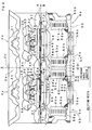
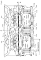
- Fig. 8 shows an example of mechanism structure on a cam plate 3a for selectively knit-driving the knitting needle 20 of Fig. 7 in the carriage 3 of Fig. 6 .
- two sets of cam systems 4a and 4b are mounted.
- Each of the cam systems 4a and 4b which are divided by the centerline 3b include a transfer cam for both sending and receiving 31, a fixed needle raising cam 32, a movable needle raising cam 33, stitch cams 34 and 35, and needle guide cams 36 and 37.
- the transfer cam for both sending and receiving 31 works on the transfer operation butt 22b of Fig. 7 .
- the fixed needle raising cam 32, the movable needle raising cam 33, and stitch cams 34 and 35 work.
- needle guide cams 36 and 37 work, and at the same time, in accordance with the needle selecting condition, a tuck presser 41 and a half presser 42, or a fixed presser 43 work.
- the position of the pressing butt 23a is decided to be either of three positions of A, H, or B. No presser is disposed at position A and the pressing butt 23a is not subject to pressure. At position H, the pressing butt 23a is subject to pressure by the tuck presser 41 and the half presser 42.
- the tuck presser 41 and the half presser 42 are able to be changed over between action and no-action, and when it is set to the no-action, the pressing butt 23a is not pressurized.
- the fixed presser 43 constantly pressurizes the pressing butt 23a at position B.
- Needle selecting mechanisms 5a and 6a; 5b and 6b on both sides of each of cam systems 4a and 4b include needle selecting actuators 50a and 51a; 50b and 51b, selector raising cams 52a and 53a; 52b and 53b, and selector guide cams for raising 54 and 55, respectively.
- the needle selecting mechanisms 6a and 5b include raising protrusions 54a and 54b of the selector guide cam for raising 54, respectively, too.
- the needle selecting mechanisms 5a and 6b include raising protrusions 55a and 55b of the selector guide cam for raising 55, respectively, too.
- the needle selecting mechanisms 6a and 5b include clearing protrusions 56a and 56b of the selector guide cam for clearing 56, respectively, too.
- the needle selecting mechanisms 5a and 6b include clearing protrusions 57a and 57b of the selector guide cam for clearing 57, respectively, too.
- Clearing protrusions 56a, 56b, 57a, and 57b work on the upper butt 24a of the selector 24 shown in Fig. 7
- selector raising cams 52a, 52b, 53a, and 53b as well as raising protrusions 54a, 54b, 55a, and 55b work on the lower butt 24b of the selector 24.
- selector floating cams 59a and 59b work, which are included in the reset mechanisms 7a and 7b, while the upper butt 24a lowered to the reference state corresponding to position B by the guide cam for clearing 58.
- pressing claws 60 of needle selecting actuators 50a, 50b, 51a, and 51b work.
- a plurality of pressing claws 60 are disposed in accordance with the type of the position of the needle selection butt 24c.
- the pressing claw 60 is electromagnetically controlled by a solenoid, etc., and displaces in such a manner not to press the needle selection butt 24c in the selection state and presses the needle selection butt 24c to sink the selector 24 in the needle groove in the non-selection state.
- the selector 24 is disposed in such a manner that the position of the needle selection butt 24c is deviated between adjacent knitting needles 20, and each of pressing claws 60 works on the individual needle selection butt 24c.
- the selector raising cam 52a and the selector raising cam 53a as well as the selector raising cam 52b and the selector raising cam 53b are able to be changed over in such a manner that the leading side protrudes and the trailing side is immersed (for example, see Patent Citation 2).
- the needle is selected in two steps by the use of the needle selecting mechanisms 5b and 6a.
- the needle selecting actuator 50b the lower butt 24b of the selector 24 in the needle selection state is pushed up by the raising protrusion 54a of the selector guide cam for raising 54.
- the upper butt 24a is pushed down by the clearing protrusion 56c of the selector guide cam for clearing 56; then, the selector 24 is pushed up by the push-up force received from the selector guide cam 54.
- the select jack 23 is pushed up to the position H.
- the selector raising cam 53a in the protrusion state works on the lower butt 24b below the selector 24, and pushes up the select jack 23 to position A via the selector 24.
- the knitting operation is carried out by the cam system 4b, needles are selected in two steps only by the needle selecting mechanism 6b by using preliminary needle selection.
- cam systems 4a and 4b are mounted to the carriage 3, all the cam systems 4a and 4b are not always used for every course knitting. It is possible to knit two courses of fabric by one travel of the carriage 3 if knitting yarn is supplied taking the yarn feeder 8 to each cam system 4a and 4b, respectively, to knit the fabric, but different knitting yarns are used alternately for each course. In the event that the fabric is knitted continuously by the same knitting yarn, one cam system only is used. In addition, cam systems 4a and 4b may be sometimes used by sorting them into cam system for knitted loop formation and that for loop transferring.
- the running stroke of the carriage 3 is desirably as small as possible with respect to the knitting width W. This is because the increased running stroke relative to the knitting width W increases the ratio of time in which no knitting operation takes place and deteriorates the knitting efficiency.
- Prior art document GB 1 519 785 A discloses a method of selecting needles on a flat knitting machine wherein needle selection takes place in two stages, i.e., a first stage during which needles are selectively pre-conditioned by an electromagnetic pre-selector system to follow at a later time alternative paths at an associated cam system, and a second stage during which the pre-selected needles are mechanically engaged and operated by the said cam system to complete the needle selection the time lag between the two stages being achieved either by virtue of the pre-selector system being spaced apart ahead of the associated cam system in the direction of travel of the cam carriage and the two stages being completed during a single stroke of the cam carriage or by virtue of the pre-selector system and the associated cam system being coincident or substantially so and the pre-se
- a double head flat knitting machine which includes at least one front and one rear needle bed and two carriages movable to-and-fro over the needle beds by means of a drive.
- the drive for the carriages is a reversing drive with a selectively-adjustable carriage stroke and the carriages are detachably connectible with the reversing drive in at least two positions.
- the mentioned object of the present invention is also met by a flat bed knitting machine according to claim 4.
- the present invention is a method for selecting needles, in a flatbed knitting machine to knit a fabric by a carriage, on which plural sets of cam systems for knit-driving are mounted and which runs back and forth along a needle bed, by providing a needle selecting mechanism to divide knitting needles into two groups on both sides in the running direction of each cam system, and by selecting needles in two steps between cam systems when adjacent cam systems are used together, wherein;
- the present invention is a flatbed knitting machine to knit a fabric by a carriage, on which plural sets of cam systems for knit-driving are mounted and which runs back and forth along a needle bed, by providing a needle selecting mechanism to divide knitting needles into two groups on both sides in the running direction of each cam system, and by selecting needles in two steps between cam systems when adjacent cam systems are used together, comprising:
- plural sets of cam systems for knit-driving are mounted to a carriage of a flatbed knitting machine, and needle selecting mechanisms that divide knitting needles into two groups are installed to each of the cam systems on both sides of the running direction.
- the carriage is able to be stopped at the position in which the needle selecting mechanism on the other side of the cam systems in use at least runs out the knitting width. It is possible to bring the carriage stop position closer to the end portion of the knitting width and to shorten the carriage running stroke in order to enhance the knitting efficiency.
- one-step needle selection is carried out as a preliminary needle selection, and in the needle selecting mechanisms on the other side of the needle selecting mechanism which conducted the preliminary needle selection, the preliminary selection state is not disarrayed.
- a reset mechanism is installed to reset all the knitting needles to the reference state after providing a space so that knitting needles are guided to different routes in accordance with the needle selection results after the needles are selected.
- the first-step needle selection is conducted in the needle selecting mechanism on the other side after the carriage reverses the running direction, the knitting needles are selected as is the case of the preliminary needle selection, and the preliminary needle selection state is eventually able to be kept disarrayed.
- three or more sets of cam systems are mounted to the carriage and in the event that cam systems not in use are located on both sides of the cam systems in use, the preliminary needle selection is conducted at the end portions on both sides of the knitting width.
- the running stroke can be shortened on both sides of the carriage running.
- a flatbed knitting machine includes a setting means and a control means.
- the setting means sets a preliminary needle selection section, when all the cam systems disposed on the other side of the cam systems used for knitting while the carriage runs toward the one side are not used, and all the cam systems on the other side are not used when the carriage reverses running direction to the other side.
- This kind of setting is able to be implemented on the basis of the results designated throughout continuous plurality of courses or on the basis of the results judged in accordance with the knitting data that controls the flatbed knitting machine.
- the control means controls each needle selecting mechanism so as to select needles in one step as the preliminary needle selection by the needle selecting mechanisms on the other side of the cam systems in use while the carriage runs to the one side before reversing the running direction, and so as not to disarray the preliminary needle selection state by needle selecting mechanisms on the side other than the needle selecting mechanisms which conducted the preliminary needle selection.
- the carriage is stopped at the position in which the needle selecting mechanism on the other side of the cam systems in use runs out at least the knitting width when the carriage runs out the one side of the knitting width of the fabric, and the running stroke is shortened and the knitting efficiency can be enhanced.
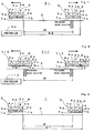
- Fig. 1 shows basic structure of a flatbed knitting machine 61 as one embodiment of the present invention.
- like reference characters are designated to portions corresponding to the structure shown in Fig. 6 through Fig. 8 , and redundant explanation is omitted.
- a preliminary needle selection section is provided as shown shaded at the end portion on the right side of the knitting width.
- the cam systems 4a and 4b are judged as being in use when they are used for knit loop forming operation such as knit, tuck, and miss with a yarn feeder 8 taken along, loop transferring operation, or the like.
- Setting of the preliminary needle selection section and control relating to the preliminary needle selection section are conducted by a controller 62.
- a controller 62 In the flatbed knitting machine 1 of Fig. 6 , another controller that controls a carriage 3, cam systems 4a and 4b, and needle selecting mechanisms 5a and 6a; 5b and 6b, is provided but illustration is omitted.
- the controller 62 of Fig. 1 has functions similar to those of a controller of a conventional flatbed knitting machine 1 as well as functions relating to section setting of preliminary needle selection at the end portion of knitting width.
- the first-step needle selection similar to the preliminary needle selection of Patent Citation 1 is conducted in the needle selecting mechanism which follows the cam system 4b when the carriage 3 runs to the right side.
- the needle selecting mechanism 6a can enter, too.
- the needle selecting mechanism 6a is controlled by the controller 62 so as not to disarray the preliminary needle selection state when it enters the preliminary needle selection section. In order not to disarray the preliminary needle selection state, for example all the knitting needles should be selected.
- the knitting needle 20, which is once set to the non-needle selection state as shown in Fig. 7 is held in the needle groove and is unable to float until selector floating cams 59a and 59b of the reset mechanisms 7a and 7b are activated.
- the stop position of the carriage 3 when running to the right can be designated at, for example, a position from which the needle selecting mechanism 5b runs out the end portion of the knitting width. Even if the stop position of the carriage 3 when running to the left is the same as in the flatbed knitting machine 1 of Fig. 6 , it is possible to reduce the necessary space of the carriage 3 at the time of right running and the stop position can be brought close to the end of the knitting width.
- a running stroke S2 of Fig. 1 is able to be reduced, for example, several tens of mm, compared to the running stroke S1 of Fig. 6 , and by accumulation of shortening, the knitting efficiency can be improved by about several percent.
- Fig. 2 shows the relationship between the layout of the mechanism on the cam plate 3a of the carriage 3 and the preliminary needle selection section.
- the layout of the mechanism on the cam plate 3a is same as that of Fig. 8 but the right-side end of the knitting width is able to be set on the right of the centerline 3b. If all the needle selecting actuators 51a of the needle selecting mechanism 6a are kept in the needle selection state when the carriage 3 which conducts preliminary needle selection runs to the right, a needle selection butt 24c of a selector 24 of the knitting needle 20 selected in the needle selecting actuator 50b is not pressed and the selector 24 keeps the selection state to float in the needle groove.
- a lower butt 24b is subject to the operation of a protruding selector raising cam 53a and ascends as shown on the leftward side of a broken arrow.
- a selector raising cam 53a ascends as shown on the leftward side of a broken arrow.
- an upper butt 24a, too ascends as shown on the rightward side of the broken arrow, and at the same time, a select jack 23 is pushed up, and a pressing butt 23a, too, ascends as shown on the leftward side of the broken arrow.
- the pressing butt 23a ascends to position A and is not subject to pressure by a half presser 42 at position H and a fixing presser 43 at position B, and therefore a knitting operation butt 22a of a needle jack 22 ascends along the gradient of the fixed needle raising cam 32 as shown by the left-pointing broken arrow, and the knitting needle 20 advances to the needle bed gap in the needle groove.
- Such rightward running of the carriage 3 is continued in this way, the knitting operation butt 22a of the needle jack 22 which belongs to the knitting needle 20 same as that of the selector 24, which has relatively run leftward and passed the needle selecting actuator 51a, comes close to the stitch cam 35 of the cam system 4a.
- the stitch cam 35 is on the leading side and ascends to the zero stitch value position, and therefore, there is no problem if it is the case in that the knitting operation butt 22a comes close to the stitch cam 35.
- the selector 24 and the select jack 23 which have ascended return to the original position as shown with the rightward side of the broken arrow.
- the knitting operation butt 22a of the needle jack 22 does not return and holds the ascending position as shown with the broken arrow but if it is a small ascending extent that reaches the bottom of the stitch cam 35, there is no problem.
- the selector 24 of the knitting needle 20 which is brought to the non-needle selection state in the preliminary needle selection sinks in the needle groove because the needle selection butt 24c is pressed in the needle selecting actuator 50b, and is not subject to the operation of the needle selecting actuator 51a.
- the butt 24b below the selector 24 which sinks in the needle groove is not subject to pushup operation by raising protrusions 54b and 54a of selector guide cam for raising 54 or selector raising cam 53a. In this way, ascending of the knitting needle 20 after the needle selecting actuator 51a passes is carried out by push-up of the selector raising cam 53a to the lower butt 24b below the selector 24.
- Enabling the selector raising cam 53a to independently float and sink and allowing it to be immersed in the preliminary needle selection section can prevent the knitting needle 20 from ascending at all even if it is brought to the preliminary needle selection state.
- the knitting operation butt 22a of the knitting needle 20 preliminarily selected holds the position H route, and therefore in the case of the layout of the mechanism on the cam plate 3a as described above, the knitting motion butt 22a may enter the knit route and be guided to the top. In such event, even in the position H route, the half presser 42 is operated to prevent the knitting motion butt 22a from entering the knit route.
- the selector 24 sunk in the needle groove in preliminary needle selection resets to float, too.
- the first-step needle selection should be conducted by the needle selecting actuator 51a when the carriage 3 traverses the running direction to the left, but preliminary needle selection need not to be conducted. Consequently, the leftward boundary of the preliminary needle selection section may be the position where operation of the selector floating cam 59a is started at the maximum.
- preliminary needle selection must be conducted without fail.
- the right boundary of the preliminary needle selection section is the position where preliminary needle selection by the needle selecting mechanism 5b is finished when the carriage 3 stops at the end right of the knitting width.
- Preliminary needle selection is the first-step needle selection by the needle selecting actuator 50b, and the needle selection state is established when the lower butt 24b below the selector 24 is pushed up to the top of the raising protrusion 54b of the selector guide cam for raising 54.
- the vicinity of the position of the center line 3b of the cam plate 3a may be set as the right boundary of the knitting width, too.
- the right boundary of the knitting width that is, the right boundary of the preliminary needle selection section may be provided in the range from the center line 3b to the position of the raising protrusion 54b of the selector guide cam for raising 54. This position can shorten the running stroke of the carriage 3 by bringing it up near the right side of the figure as much as possible.
- Fig. 3 schematically shows system structure of a controller 62 that enables operation of the preliminary needle selection as described above in the flatbed knitting machine 61 of Fig. 1 .
- the needle beds 2 are installed in front and rear of the needle bed gap, and to the front and rear needle beds 2, carriages 3 are installed, respectively.
- Needle selection of the knitting needles 20 by the needle selecting actuators 50a, 50b, 51a, and 51b mounted to the carriage 3 is conducted by determining the position of each carriage 3 relative to the needle bed 2.
- the position of the carriage 3 can be directly detected by the position sensor 70 relative to the needle bed 2.
- the needle selection gauge is disclosed in, for example, Domestic Re-publication of PCT International Publication for Patent Application No. 2003-091490 , and the like.
- the controller 62 controls carriages 3 installed to each front and rear needle bed 2 of the flatbed knitting machine 61 by the front carriage control unit 71 and the rear carriage control unit 72, respectively.
- the position of the carriage 3 of each needle bed 2 is detected by a carriage position two-phase signal detector 73 on the basis of outputs of position sensors 70 which are installed corresponding to arrangement pitch of the knitting needle 20 to the needle selection gauge and which magnetically or optically detect irregularities or bright and dark fringes, or the like.
- the needle selecting actuators 50a, 50b, 51a and 51b of the carriage 3 of the front and rear needle beds 2 are driven by a front actuator ON/OFF output unit 74 and a rear actuator ON/OFF output unit 75, respectively.
- the front carriage control unit 71 Since inside of the front carriage control unit 71 and inside of the rear carriage control unit 72 have basically equivalent structure, the front carriage control unit 71 only is explained and the description on the rear carriage control unit 72 is omitted.
- a software processing unit 80 As a software processing unit 80, a carriage speed calculator 81, speed correction unit 82, and needle selection data storage unit 83 are included.
- a hardware processing unit 90 As a hardware processing unit 90, a carriage position counter 91, adder 92, output position judgment device 93 and an actuator ON/OFF setter 94 are included.
- the needle selection data stored in the needle selection data storage unit 83 covers the overall needle bed 2.
- This needle selection data is outputted from a CPU100 that totally controls the knitting operation of the flatbed knitting machine 61.
- the CPU100 combines the data preliminarily saved in a knit fabric data storage unit 101 and a knitting machine parameters storage unit 102 and enters it as the knitting data 103 and outputs the needle selection data for each .. knitting course.
- the knit fabric data storage unit 101 data on shapes and patters of knit fabric to be knitted, knitting yarns to be used, and others are prepared in advance and stored.
- the knitting machine parameter storage unit 102 parameters necessary for knitting by the flatbed knitting machine 61 are stored.
- the data concerning the section in which preliminary needle selection as shown in Fig. 1 is also stored.
- a carriage drive unit 104 controls the direction, speed, and running range in which the carriage drive unit 104 drives the carriage 3.
- the position of the carriage 3 with respect to the front and rear needle beds 2 are entered to the CPU100 as outputs of the adder 92.
- the carriage speed calculator 81, speed correction unit 82, carriage position counter 91 and adder 92 determine the position of the carriage 3 with respect to the needle bed 2.
- the CPU100 can control in such a manner as to properly select the knitting needle 20 relating to the preliminary needle selection section on the basis of the position of the carriage 3 with respect to the needle bed 2.
- Fig. 4 schematically shows a control procedure by CPU100 of the controller 62 of Fig. 3 .
- the procedure begins from Step s0, and in Step s1, the knitting data is entered for each course. In the vicinity of the end of each course, the knitting data on the vicinity of the starting end of the following course is entered. At the finishing end and starting end, a section which is possible to be set as a section of preliminary needle selection is included.
- Step s2 whether or not unused cam systems are included in the cam systems mounted to the carriage 3 is determined. The presence or absence of unused cam systems may be designated and entered in advance by the operator or may be automatically determined from the knitting data of courses before and after.
- Step s3 the preliminary needle selection section is set in Step s3.
- Step s4 the carriage 3 is controlled.
- Step s5 it is determined whether or not the trailing side of the used cam system, for example the needle selecting mechanism 5b relative to the cam system 4b at the time of a rightward running, enters in the preliminary needle selection section. If the needle selecting mechanism 5b has not entered, judgment repeats until the needle selecting mechanism 5b enters.
- Step s6 preliminary needle selection by the needle selecting mechanism 5b is conducted in Step s6.
- Step s7 whether or not the unused cam system, for example the needle selecting mechanism 6a leading the cam system 4a, has entered in the preliminary needle selection section. If the needle selecting mechanism 6a has not entered in the section, judgment repeats until the needle selecting mechanism 6a enters in the section.
- Step s8 the needle selecting mechanism 6a is brought into the total needle selection state so as not to disarray the preliminary needle selection state.
- Step s9 it is judged whether or not the carriage 3 reaches the stop position. For example, as shown in Fig. 2 , when the right end of the knitting width reaches the rightward boundary of the section, it is judged that the carriage 3 has reached the stop position. If the carriage 3 has not yet reached the stop position, the carriage 3 is decelerated and moved to run to the stop position. When the carriage 3 reaches the stop position, the carriage 3 is stopped in Step s10. Change over of rising and sinking of the selector raising cam 52a and selector raising cam 53a, and selector raising cam 52b and selector raising cam 53b are conducted, too.
- Step s11 running direction of the carriage 3 is reversed, and for example, leftward running is started as against the above-mentioned rightward running.
- Step s12 the controller controls the needle selecting mechanism 5b which leads the cam system 4b to be used to carry out the second-step needle selection to the preliminary needle selection.
- Step s13 it is judged whether or not the needle selecting mechanism 6a which trails the unused cam system 4a that leads the cam system 4b runs out the preliminary needle selection section.
- the needle selecting mechanism 6a continues the total needle selection state set in Step s8 until the needle selecting mechanism 6a runs out the preliminary needle selection section.
- the needle selecting mechanism 6a carries out first-step needle selection to conduct knitting operation by the cam system 4b in Step s14 when the needle selecting mechanism 6a runs out the preliminary needle selection section. Then, the control returns to Step s1, and knitting data is entered for the remainder courses at least including the course in which the carriage 3 began running.
- Step s2 When it is judged that the unused cam system is not included in the cam system in Step s2, the carriage is driven in Step s15 and the needle selection control similar to conventional control takes place in Step s16.
- Step s17 When the carriage 3 reaches the termination end of the running stroke, in Step s17, whether or not knitting is finished is judged and if it is not finished, the control returns to Step s1, and if knitting is finished, knitting is completed in Step s18.
- the preliminary needle selection section is set in Step s3
- Fig 5 schematically shows the needle selection method accompanied by the setting of the preliminary needle selection section in a flatbed knitting machine 111 as the other embodiment of the present invention.
- a controller 112 is used to control a carriage 113 with three cam systems 4a, 4b, and 4c mounted in, the procedure similar to that in Fig. 4 , and preliminary needle selection sections are provided on both sides of the knitting width W.
- the cam system 4b at the center only is used for knit loop forming operation such as knit, tuck, and miss with a yarn feeder 8 taken along, or knitting loop transferring operation, or the like.
- the left-side cam system 4a retained in the knitting width W when running to the right and with the right-side cam system 4c retained in the knitting width W when running to the left
- running stroke of the carriage 113 can be shortened on both sides.
- the cam system 4c in the event that concerning the three cam systems 4a, 4b, and 4c, the right-side cam system 4c only is used, the cam system 4c should be brought to have correspondence with the cam system 4b of Fig. 1 , and the needles should be selected in the preliminary needle selection section in the needle selecting mechanism 5c.
- the preliminary needle selection section should be provided on the left side of the knitting width W and the needles should be selected in the preliminary needle selection section in the needle selecting mechanism 6a.
- the carriage 3 must run rightward until the used cam system 4a goes through the knitting end if a used cam system 4a also exists.
- the preliminary needle selection section should be set to zero.
- the preliminary needle selection section may be provided in the similar manner and the carriage running stroke can be shortened.
Landscapes
- Engineering & Computer Science (AREA)
- Textile Engineering (AREA)
- Knitting Machines (AREA)
Claims (4)
- Verfahren zum Auswählen von Nadeln (20) in einer Flachstrickmaschine (61, 111) für das Stricken eines Gestricks unter Verwendung eines Schlittens (3, 113), auf dem eine Vielzahl von Sätzen von Schlosssystemen (4a, 4b, 4c) für einen Strickantrieb montiert sind und der nach hinten und nach vorne entlang eines Nadelbetts (2) läuft, durch das Vorsehen eines Nadelauswahlmechanismus (5a, 5b, 5c, 6a, 6b, 6c) zum Teilen von Stricknadeln (20) in zwei Gruppen auf beiden Seiten in der Laufrichtung jedes Schlosssystems (4a, 4b, 4c) und durch das Auswählen von Nadeln (20) in zwei Schritten zwischen Schlosssystemen (4a, 4b, 4c), wenn benachbarte Schlosssysteme (4a, 4b, 4c) gemeinsam verwendet werden,
wobei:wenn der Schlitten (3, 113) zu einer Seite läuft und dann die Laufrichtung zu der anderen Seite umkehrt, und wenn alle Schlosssysteme (4a, 4b, 4c), die auf der anderen Seite der für das Stricken des Gestricks verwendeten Schlosssysteme (4a, 4b, 4c) angeordnet sind, nicht verwendet werden,derart dass, wenn der Schlitten (3, 113) von einer Seite einer Strickbreite des Gestricks herausläuft, der Schlitten (3, 113) an der Position stoppen kann, an welcher ein Nadelauswahlmechanismus (5a, 5b, 5c, 6a, 6b, 6c) auf der anderen Seite der verwendeten Schlosssysteme (4a, 4b, 4c) wenigstens aus der Strickbreite herausläuft, undan dem Endteil auf der einen Seite der Strickbreite, auf welcher ein Nadelauswahlmechanismus (5a, 5b, 5c, 6a, 6b, 6c), der den Nadelauswahlmechanismus (5a, 5b, 5c, 6a, 6b, 6c) auf der anderen Seite führt, keine Nadeln (20) auswählen kann, auch wenn der Schlitten (3, 113) die Laufrichtung zu der anderen Seite umkehrt, eine Nadelauswahl in einem Schritt als eine vorläufige Nadelauswahl in dem Nadelauswahlmechanismus (5a, 5b, 5c, 6a, 6b, 6c) auf der anderen Seite des verwendeten Schlosssystems durchgeführt wird, wenn der Schlitten (3, 113) zu der einen Seite läuft, bevor er die Laufrichtung umkehrt, und in einem Nadelauswahlmechanismus (5a, 5b, 5c, 6a, 6b, 6c) auf der anderen Seite des Nadelauswahlmechanismus (5a, 5b, 5c, 6a, 6b, 6c), der die vorläufige Nadelauswahl durchgeführt hat, der vorläufige Nadelauswahlzustand aufrechterhalten wird, um nicht in Unordnung gebracht zu werden. - Verfahren zum Auswählen von Nadeln (20) nach Anspruch 1, wobei:drei oder mehr Sätze von Schlosssystemen (4a, 4b, 4c) an dem Schlitten (3, 113) montiert sind, undwenn die nicht verwendeten Schlosssysteme (4a, 4b, 4c) auf beiden Seiten der verwendeten Schlosssysteme (4a, 4b, 4c) angeordnet sind, die vorläufige Nadelauswahl an den Endteilen auf beiden Seiten der Strickbreite durchgeführt wird.
- Verfahren zum Auswählen einer Nadel (20) nach Anspruch 1 oder 2, wobei:in jedem der Schlosssysteme (4a, 4b, 4c) ein Rücksetzmechanismus (7a, 7b, 7c) zum Zurücksetzen aller Nadelauswahlzustände zu dem Bezugszustand auf der Innenseite der Nadelauswahlmechanismen (5a, 5b, 5c, 6a, 6b, 6c) auf beiden Seiten installiert ist, unddie vorläufige Nadelauswahl startet in einem Abschnitt von einem Abschlussende eines Bereichs, in dem der Rücksetzmechanismus (7a, 7b, 7c) die Stricknadel (20) zu dem Bezugszustand zurücksetzt, bevor der Schlitten stoppt, bis zu einem Einleitungsende eines Bereichs, in dem ein Nadelauswahlmechanismus (5a, 5b, 5c, 6a, 6b, 6c), der in der Strickbreite in Nachbarschaft zu dem die vorläufige Nadelauswahl durchführenden Nadelauswahlmechanismus (5a, 5b, 5c, 6a, 6b, 6c) verbleibt, Nadeln (20) auswählen kann, wenn der Schlitten (3, 113) die Laufrichtung umkehrt, und an dem Endteil der Strickbreite endet.
- Flachstrickmaschine (61, 111) zum Stricken eines Gestricks unter Verwendung eines Schlittens (3, 113), auf dem eine Vielzahl von Sätzen von Schlosssystemen (4a, 4b, 4c) für einen Strickantrieb montiert sind, und der nach hinten und nach vorne entlang eines Nadelbetts (2) läuft, durch das Vorsehen eines Nadelauswahlmechanismus (5a, 5b, 5c, 6a, 6b, 6c) zum Teilen von Stricknadeln (20) in zwei Gruppen auf beiden Seiten in der Laufrichtung jedes Schlosssystems (4a, 4b, 4c) und durch das Auswählen von Nadeln (20) in zwei Schritten zwischen Schlosssystemen (4a, 4b, 4c), wenn benachbarte Schlosssysteme (4a, 4b, 4c) gemeinsam verwendet werden, gekennzeichnet durch:eine Setzeinrichtung zum Setzen eines vorläufigen Nadelauswahlabschnitts an dem Endteil auf einer Seite der Strickbreite, wenn alle Schlosssysteme (4a, 4b, 4c), die auf der anderen Seite der für das Stricken verwendeten Schlosssysteme (4a, 4b, 4c) angeordnet sind, nicht verwendet werden, während der Schlitten (3, 113) zu der einen Seite läuft, und alle Schlosssysteme (4a, 4b, 4c) auf der anderen Seite ebenfalls nicht verwendet werden, während der Schlitten (3, 113) die Laufrichtung zu der anderen Seite umkehrt, undeine Steuereinrichtung (62, 112) zum Steuern jedes Nadelauswahlmechanismus (5a, 5b, 5c, 6a, 6b, 6c) in dem vorläufigen Nadelauswahlabschnitt, um Nadeln (20) in einem Schritt als eine vorläufige Auswahl durch die Nadelauswahlmechanismen (5a, 5b, 5c, 6a, 6b, 6c) auf der anderen Seite der verwendeten Schlosssysteme (4a, 4b, 4c) auszuwählen, während der Schlitten (3, 113) zu der einen Seite läuft, bevor er die Laufrichtung zu der anderen Seite umkehrt, und um den Nadelauswahlmechanismus (5a, 5b, 5c, 6a, 6b, 6c) auf der anderen Seite des Nadelauswahlmechanismus (5a, 5b, 5c, 6a, 6b, 6c), der die vorläufige Nadelauswahl durchgeführt hat, derart zu steuern, dass ein vorläufiger Nadelauswahlzustand durch die Nadelauswahlmechanismen (5a, 5b, 5c, 6a, 6b, 6c) auf der anderen Seite der Nadelauswahlmechanismen (5a, 5b, 5c, 6a, 6b, 6c), die die vorläufige Nadelauswahl durchgeführt haben, nicht in Unordnung gebracht wird, und um weiterhin den Schlitten (3, 115) derart zu steuern, dass er an der Position stoppt, an welcher der Nadelauswahlmechanismus (5a, 5b, 5c, 6a, 6b, 6c) auf der anderen Seite der verwendeten Schlosssysteme (4a, 4b, 4c) aus wenigstens der Strickbreite herausläuft, wenn der Schlitten (3, 113) aus einer Seite der Strickbreite des Gestricks herausläuft.
Applications Claiming Priority (2)
| Application Number | Priority Date | Filing Date | Title |
|---|---|---|---|
| JP2006349569 | 2006-12-26 | ||
| PCT/JP2007/001460 WO2008078415A1 (ja) | 2006-12-26 | 2007-12-22 | 選針方法および横編機 |
Publications (3)
| Publication Number | Publication Date |
|---|---|
| EP2116643A1 EP2116643A1 (de) | 2009-11-11 |
| EP2116643A4 EP2116643A4 (de) | 2014-11-19 |
| EP2116643B1 true EP2116643B1 (de) | 2016-03-30 |
Family
ID=39562210
Family Applications (1)
| Application Number | Title | Priority Date | Filing Date |
|---|---|---|---|
| EP07849879.7A Not-in-force EP2116643B1 (de) | 2006-12-26 | 2007-12-22 | Verfahren zur nadelselektion und flachstrickmaschine |
Country Status (4)
| Country | Link |
|---|---|
| EP (1) | EP2116643B1 (de) |
| JP (1) | JP5161108B2 (de) |
| CN (1) | CN101553608B (de) |
| WO (1) | WO2008078415A1 (de) |
Families Citing this family (7)
| Publication number | Priority date | Publication date | Assignee | Title |
|---|---|---|---|---|
| JP5813975B2 (ja) * | 2011-03-28 | 2015-11-17 | 株式会社島精機製作所 | 横編機 |
| JP5828723B2 (ja) * | 2011-09-09 | 2015-12-09 | 株式会社島精機製作所 | 横編機による編成方法及び編成データの編集装置 |
| CN103205857B (zh) * | 2013-01-05 | 2014-09-03 | 福建睿能科技股份有限公司 | 电脑横机选针控制系统及控制方法 |
| CN105624909B (zh) * | 2015-12-31 | 2018-05-04 | 福建睿能科技股份有限公司 | 横机的机头运动控制方法及系统 |
| CN107157017B (zh) * | 2017-06-30 | 2023-04-21 | 信泰(福建)科技有限公司 | 嵌绳一体鞋面及其编织工艺 |
| CN108374231B (zh) * | 2018-04-04 | 2024-03-22 | 浙江睿丰智能科技有限公司 | 一种用于横编织机的编织系统 |
| CN111218769B (zh) * | 2020-01-10 | 2021-06-22 | 杭州之山智控技术有限公司 | 一种预测提前选针方法 |
Family Cites Families (10)
| Publication number | Priority date | Publication date | Assignee | Title |
|---|---|---|---|---|
| DE2436065B2 (de) * | 1974-07-26 | 1979-05-10 | H. Stoll Gmbh & Co, 7410 Reutlingen | Mustervorrichtung für eine Flachstrickmaschine |
| JPS6120670B1 (de) * | 1979-09-28 | 1986-05-23 | Shima Idea Center Co Ltd | |
| JPS6120670A (ja) * | 1984-07-06 | 1986-01-29 | Mitsubishi Heavy Ind Ltd | ツイント−チ型すみ肉溶接装置 |
| DE3429913C1 (de) * | 1984-08-14 | 1986-04-17 | Universal Maschinenfabrik Dr. Rudolf Schieber GmbH & Co KG, 7081 Westhausen | Doppelkopfflachstrickautomat |
| DE3541171A1 (de) * | 1985-11-21 | 1987-05-27 | Stoll & Co H | Flachstrickmaschine mit nadelauswahleinrichtung |
| JPH05156553A (ja) * | 1991-12-06 | 1993-06-22 | Shima Seiki Mfg Ltd | 横編機におけるカム出没切り換え装置 |
| JP2794144B2 (ja) * | 1992-10-22 | 1998-09-03 | 株式会社島精機製作所 | 目移し装置を有する横編機 |
| DE19914080A1 (de) * | 1999-03-27 | 2000-09-28 | Stoll & Co H | Flachstrickmaschine |
| WO2003091490A1 (en) | 2002-04-23 | 2003-11-06 | Shima Seiki Mfg., Ltd. | Magnetic needle selecting device of weft knitting machine |
| CN2716308Y (zh) * | 2004-06-14 | 2005-08-10 | 杭州天松智能设备有限公司 | 横机织针选针装置 |
-
2007
- 2007-12-22 EP EP07849879.7A patent/EP2116643B1/de not_active Not-in-force
- 2007-12-22 JP JP2008550965A patent/JP5161108B2/ja not_active Expired - Fee Related
- 2007-12-22 WO PCT/JP2007/001460 patent/WO2008078415A1/ja not_active Ceased
- 2007-12-22 CN CN200780044039.1A patent/CN101553608B/zh not_active Expired - Fee Related
Also Published As
| Publication number | Publication date |
|---|---|
| WO2008078415A1 (ja) | 2008-07-03 |
| EP2116643A1 (de) | 2009-11-11 |
| JP5161108B2 (ja) | 2013-03-13 |
| EP2116643A4 (de) | 2014-11-19 |
| CN101553608A (zh) | 2009-10-07 |
| JPWO2008078415A1 (ja) | 2010-04-15 |
| CN101553608B (zh) | 2011-04-20 |
Similar Documents
| Publication | Publication Date | Title |
|---|---|---|
| EP2116643B1 (de) | Verfahren zur nadelselektion und flachstrickmaschine | |
| EP1972706B1 (de) | Flachstrickmaschine mit ketteneintrag und damit durchgeführtes strickverfahren | |
| EP0594169B1 (de) | Flachstrickmaschine mit Übertragevorrichtung | |
| EP1672106B1 (de) | Schloss für eine flachstrickmaschine | |
| EP1975295B1 (de) | Nadelwahlvorrichtung für kulierwirkmaschine | |
| US5557948A (en) | Yarn guiding method and apparatus for flat knitting machine | |
| US6568223B1 (en) | Guide mechanism of knitting member and compound needle assembling the guide mechanism therein | |
| EP2025785B1 (de) | Strickverfahren für intarsienmusterware und flachstrickmaschine | |
| KR101709944B1 (ko) | 스플릿 스티치 방법 | |
| KR100554200B1 (ko) | 횡편기에 의한 스티치 루프의 결합 방법 | |
| JP4977383B2 (ja) | 横編機の編成用カム装置 | |
| JP2009068122A (ja) | 横編機およびその選針方法 | |
| EP0924327B1 (de) | Flachstrickmaschine mit Umhängplatine-Umhängvorrichtung | |
| EP1541734B1 (de) | Flachstrickmaschine mit einer nadelselektorvorrichtung | |
| EP0698679B1 (de) | Strickschlussteil und Schluss | |
| KR100768347B1 (ko) | 코이동 기구를 구비하는 횡편기 및 코이동 방법 | |
| EP0955402B1 (de) | Flachstrickmaschine mit Maschenübertragevorrichtung und Verfahren zum Maschenübertragen | |
| KR101329209B1 (ko) | 탠덤 편성방법 및 횡편기 | |
| EP0604164B1 (de) | Verfahren zum Stricken eines Kreuzmusters und Vorrichtung zum Stricken eines Kreuzmusters an einer Flachstrickmachine | |
| US6668595B2 (en) | Weft knitting machine with transfer mechanism | |
| EP4306698A1 (de) | Verfahren zum stricken von durch eine flachstrickmaschine hergestellten maschenketten-gestricken |
Legal Events
| Date | Code | Title | Description |
|---|---|---|---|
| PUAI | Public reference made under article 153(3) epc to a published international application that has entered the european phase |
Free format text: ORIGINAL CODE: 0009012 |
|
| 17P | Request for examination filed |
Effective date: 20090720 |
|
| AK | Designated contracting states |
Kind code of ref document: A1 Designated state(s): AT BE BG CH CY CZ DE DK EE ES FI FR GB GR HU IE IS IT LI LT LU LV MC MT NL PL PT RO SE SI SK TR |
|
| DAX | Request for extension of the european patent (deleted) | ||
| A4 | Supplementary search report drawn up and despatched |
Effective date: 20141022 |
|
| RIC1 | Information provided on ipc code assigned before grant |
Ipc: D04B 15/96 20060101AFI20141016BHEP Ipc: D04B 15/36 20060101ALN20141016BHEP |
|
| GRAP | Despatch of communication of intention to grant a patent |
Free format text: ORIGINAL CODE: EPIDOSNIGR1 |
|
| RIC1 | Information provided on ipc code assigned before grant |
Ipc: D04B 15/96 20060101AFI20150826BHEP Ipc: D04B 15/36 20060101ALN20150826BHEP |
|
| INTG | Intention to grant announced |
Effective date: 20150925 |
|
| GRAS | Grant fee paid |
Free format text: ORIGINAL CODE: EPIDOSNIGR3 |
|
| GRAA | (expected) grant |
Free format text: ORIGINAL CODE: 0009210 |
|
| AK | Designated contracting states |
Kind code of ref document: B1 Designated state(s): AT BE BG CH CY CZ DE DK EE ES FI FR GB GR HU IE IS IT LI LT LU LV MC MT NL PL PT RO SE SI SK TR |
|
| REG | Reference to a national code |
Ref country code: GB Ref legal event code: FG4D |
|
| REG | Reference to a national code |
Ref country code: CH Ref legal event code: EP |
|
| REG | Reference to a national code |
Ref country code: AT Ref legal event code: REF Ref document number: 785512 Country of ref document: AT Kind code of ref document: T Effective date: 20160415 |
|
| REG | Reference to a national code |
Ref country code: IE Ref legal event code: FG4D |
|
| REG | Reference to a national code |
Ref country code: DE Ref legal event code: R096 Ref document number: 602007045584 Country of ref document: DE |
|
| REG | Reference to a national code |
Ref country code: LT Ref legal event code: MG4D |
|
| PG25 | Lapsed in a contracting state [announced via postgrant information from national office to epo] |
Ref country code: FI Free format text: LAPSE BECAUSE OF FAILURE TO SUBMIT A TRANSLATION OF THE DESCRIPTION OR TO PAY THE FEE WITHIN THE PRESCRIBED TIME-LIMIT Effective date: 20160330 Ref country code: GR Free format text: LAPSE BECAUSE OF FAILURE TO SUBMIT A TRANSLATION OF THE DESCRIPTION OR TO PAY THE FEE WITHIN THE PRESCRIBED TIME-LIMIT Effective date: 20160701 |
|
| REG | Reference to a national code |
Ref country code: NL Ref legal event code: MP Effective date: 20160330 |
|
| REG | Reference to a national code |
Ref country code: AT Ref legal event code: MK05 Ref document number: 785512 Country of ref document: AT Kind code of ref document: T Effective date: 20160330 |
|
| PG25 | Lapsed in a contracting state [announced via postgrant information from national office to epo] |
Ref country code: SE Free format text: LAPSE BECAUSE OF FAILURE TO SUBMIT A TRANSLATION OF THE DESCRIPTION OR TO PAY THE FEE WITHIN THE PRESCRIBED TIME-LIMIT Effective date: 20160330 Ref country code: LT Free format text: LAPSE BECAUSE OF FAILURE TO SUBMIT A TRANSLATION OF THE DESCRIPTION OR TO PAY THE FEE WITHIN THE PRESCRIBED TIME-LIMIT Effective date: 20160330 Ref country code: LV Free format text: LAPSE BECAUSE OF FAILURE TO SUBMIT A TRANSLATION OF THE DESCRIPTION OR TO PAY THE FEE WITHIN THE PRESCRIBED TIME-LIMIT Effective date: 20160330 |
|
| PG25 | Lapsed in a contracting state [announced via postgrant information from national office to epo] |
Ref country code: NL Free format text: LAPSE BECAUSE OF FAILURE TO SUBMIT A TRANSLATION OF THE DESCRIPTION OR TO PAY THE FEE WITHIN THE PRESCRIBED TIME-LIMIT Effective date: 20160330 |
|
| PG25 | Lapsed in a contracting state [announced via postgrant information from national office to epo] |
Ref country code: PL Free format text: LAPSE BECAUSE OF FAILURE TO SUBMIT A TRANSLATION OF THE DESCRIPTION OR TO PAY THE FEE WITHIN THE PRESCRIBED TIME-LIMIT Effective date: 20160330 Ref country code: IS Free format text: LAPSE BECAUSE OF FAILURE TO SUBMIT A TRANSLATION OF THE DESCRIPTION OR TO PAY THE FEE WITHIN THE PRESCRIBED TIME-LIMIT Effective date: 20160730 Ref country code: EE Free format text: LAPSE BECAUSE OF FAILURE TO SUBMIT A TRANSLATION OF THE DESCRIPTION OR TO PAY THE FEE WITHIN THE PRESCRIBED TIME-LIMIT Effective date: 20160330 |
|
| PG25 | Lapsed in a contracting state [announced via postgrant information from national office to epo] |
Ref country code: AT Free format text: LAPSE BECAUSE OF FAILURE TO SUBMIT A TRANSLATION OF THE DESCRIPTION OR TO PAY THE FEE WITHIN THE PRESCRIBED TIME-LIMIT Effective date: 20160330 Ref country code: ES Free format text: LAPSE BECAUSE OF FAILURE TO SUBMIT A TRANSLATION OF THE DESCRIPTION OR TO PAY THE FEE WITHIN THE PRESCRIBED TIME-LIMIT Effective date: 20160330 Ref country code: CZ Free format text: LAPSE BECAUSE OF FAILURE TO SUBMIT A TRANSLATION OF THE DESCRIPTION OR TO PAY THE FEE WITHIN THE PRESCRIBED TIME-LIMIT Effective date: 20160330 Ref country code: RO Free format text: LAPSE BECAUSE OF FAILURE TO SUBMIT A TRANSLATION OF THE DESCRIPTION OR TO PAY THE FEE WITHIN THE PRESCRIBED TIME-LIMIT Effective date: 20160330 Ref country code: SK Free format text: LAPSE BECAUSE OF FAILURE TO SUBMIT A TRANSLATION OF THE DESCRIPTION OR TO PAY THE FEE WITHIN THE PRESCRIBED TIME-LIMIT Effective date: 20160330 Ref country code: PT Free format text: LAPSE BECAUSE OF FAILURE TO SUBMIT A TRANSLATION OF THE DESCRIPTION OR TO PAY THE FEE WITHIN THE PRESCRIBED TIME-LIMIT Effective date: 20160801 |
|
| PG25 | Lapsed in a contracting state [announced via postgrant information from national office to epo] |
Ref country code: BE Free format text: LAPSE BECAUSE OF FAILURE TO SUBMIT A TRANSLATION OF THE DESCRIPTION OR TO PAY THE FEE WITHIN THE PRESCRIBED TIME-LIMIT Effective date: 20160330 |
|
| REG | Reference to a national code |
Ref country code: DE Ref legal event code: R097 Ref document number: 602007045584 Country of ref document: DE |
|
| PG25 | Lapsed in a contracting state [announced via postgrant information from national office to epo] |
Ref country code: DK Free format text: LAPSE BECAUSE OF FAILURE TO SUBMIT A TRANSLATION OF THE DESCRIPTION OR TO PAY THE FEE WITHIN THE PRESCRIBED TIME-LIMIT Effective date: 20160330 |
|
| PLBE | No opposition filed within time limit |
Free format text: ORIGINAL CODE: 0009261 |
|
| STAA | Information on the status of an ep patent application or granted ep patent |
Free format text: STATUS: NO OPPOSITION FILED WITHIN TIME LIMIT |
|
| 26N | No opposition filed |
Effective date: 20170103 |
|
| PG25 | Lapsed in a contracting state [announced via postgrant information from national office to epo] |
Ref country code: SI Free format text: LAPSE BECAUSE OF FAILURE TO SUBMIT A TRANSLATION OF THE DESCRIPTION OR TO PAY THE FEE WITHIN THE PRESCRIBED TIME-LIMIT Effective date: 20160330 |
|
| REG | Reference to a national code |
Ref country code: CH Ref legal event code: PL |
|
| GBPC | Gb: european patent ceased through non-payment of renewal fee |
Effective date: 20161222 |
|
| PG25 | Lapsed in a contracting state [announced via postgrant information from national office to epo] |
Ref country code: MC Free format text: LAPSE BECAUSE OF FAILURE TO SUBMIT A TRANSLATION OF THE DESCRIPTION OR TO PAY THE FEE WITHIN THE PRESCRIBED TIME-LIMIT Effective date: 20160330 |
|
| REG | Reference to a national code |
Ref country code: FR Ref legal event code: ST Effective date: 20170831 |
|
| REG | Reference to a national code |
Ref country code: IE Ref legal event code: MM4A |
|
| PG25 | Lapsed in a contracting state [announced via postgrant information from national office to epo] |
Ref country code: LU Free format text: LAPSE BECAUSE OF NON-PAYMENT OF DUE FEES Effective date: 20161222 Ref country code: LI Free format text: LAPSE BECAUSE OF NON-PAYMENT OF DUE FEES Effective date: 20161231 Ref country code: CH Free format text: LAPSE BECAUSE OF NON-PAYMENT OF DUE FEES Effective date: 20161231 Ref country code: FR Free format text: LAPSE BECAUSE OF NON-PAYMENT OF DUE FEES Effective date: 20170102 |
|
| PG25 | Lapsed in a contracting state [announced via postgrant information from national office to epo] |
Ref country code: IE Free format text: LAPSE BECAUSE OF NON-PAYMENT OF DUE FEES Effective date: 20161222 Ref country code: GB Free format text: LAPSE BECAUSE OF NON-PAYMENT OF DUE FEES Effective date: 20161222 |
|
| PG25 | Lapsed in a contracting state [announced via postgrant information from national office to epo] |
Ref country code: CY Free format text: LAPSE BECAUSE OF FAILURE TO SUBMIT A TRANSLATION OF THE DESCRIPTION OR TO PAY THE FEE WITHIN THE PRESCRIBED TIME-LIMIT Effective date: 20160330 Ref country code: HU Free format text: LAPSE BECAUSE OF FAILURE TO SUBMIT A TRANSLATION OF THE DESCRIPTION OR TO PAY THE FEE WITHIN THE PRESCRIBED TIME-LIMIT; INVALID AB INITIO Effective date: 20071222 |
|
| PG25 | Lapsed in a contracting state [announced via postgrant information from national office to epo] |
Ref country code: TR Free format text: LAPSE BECAUSE OF FAILURE TO SUBMIT A TRANSLATION OF THE DESCRIPTION OR TO PAY THE FEE WITHIN THE PRESCRIBED TIME-LIMIT Effective date: 20160330 |
|
| PG25 | Lapsed in a contracting state [announced via postgrant information from national office to epo] |
Ref country code: BG Free format text: LAPSE BECAUSE OF FAILURE TO SUBMIT A TRANSLATION OF THE DESCRIPTION OR TO PAY THE FEE WITHIN THE PRESCRIBED TIME-LIMIT Effective date: 20160330 |
|
| PG25 | Lapsed in a contracting state [announced via postgrant information from national office to epo] |
Ref country code: MT Free format text: LAPSE BECAUSE OF NON-PAYMENT OF DUE FEES Effective date: 20161222 |
|
| PGFP | Annual fee paid to national office [announced via postgrant information from national office to epo] |
Ref country code: IT Payment date: 20221111 Year of fee payment: 16 Ref country code: DE Payment date: 20221025 Year of fee payment: 16 |
|
| REG | Reference to a national code |
Ref country code: DE Ref legal event code: R119 Ref document number: 602007045584 Country of ref document: DE |
|
| PG25 | Lapsed in a contracting state [announced via postgrant information from national office to epo] |
Ref country code: DE Free format text: LAPSE BECAUSE OF NON-PAYMENT OF DUE FEES Effective date: 20240702 |
|
| PG25 | Lapsed in a contracting state [announced via postgrant information from national office to epo] |
Ref country code: DE Free format text: LAPSE BECAUSE OF NON-PAYMENT OF DUE FEES Effective date: 20240702 |
|
| PG25 | Lapsed in a contracting state [announced via postgrant information from national office to epo] |
Ref country code: IT Free format text: LAPSE BECAUSE OF NON-PAYMENT OF DUE FEES Effective date: 20231222 |