EP2116702A1 - Réservoir pour un moyen de réduction, véhicule automobile doté d'un réservoir pour un moyen de réduction et procédé de fonctionnement d'une installation SCR d'un véhicule automobile - Google Patents
Réservoir pour un moyen de réduction, véhicule automobile doté d'un réservoir pour un moyen de réduction et procédé de fonctionnement d'une installation SCR d'un véhicule automobile Download PDFInfo
- Publication number
- EP2116702A1 EP2116702A1 EP09156317A EP09156317A EP2116702A1 EP 2116702 A1 EP2116702 A1 EP 2116702A1 EP 09156317 A EP09156317 A EP 09156317A EP 09156317 A EP09156317 A EP 09156317A EP 2116702 A1 EP2116702 A1 EP 2116702A1
- Authority
- EP
- European Patent Office
- Prior art keywords
- tank
- tank volume
- volume
- motor vehicle
- reducing agent
- Prior art date
- Legal status (The legal status is an assumption and is not a legal conclusion. Google has not performed a legal analysis and makes no representation as to the accuracy of the status listed.)
- Granted
Links
Images
Classifications
-
- F—MECHANICAL ENGINEERING; LIGHTING; HEATING; WEAPONS; BLASTING
- F01—MACHINES OR ENGINES IN GENERAL; ENGINE PLANTS IN GENERAL; STEAM ENGINES
- F01N—GAS-FLOW SILENCERS OR EXHAUST APPARATUS FOR MACHINES OR ENGINES IN GENERAL; GAS-FLOW SILENCERS OR EXHAUST APPARATUS FOR INTERNAL-COMBUSTION ENGINES
- F01N3/00—Exhaust or silencing apparatus having means for purifying, rendering innocuous, or otherwise treating exhaust
- F01N3/08—Exhaust or silencing apparatus having means for purifying, rendering innocuous, or otherwise treating exhaust for rendering innocuous
- F01N3/10—Exhaust or silencing apparatus having means for purifying, rendering innocuous, or otherwise treating exhaust for rendering innocuous by thermal or catalytic conversion of noxious components of exhaust
- F01N3/18—Exhaust or silencing apparatus having means for purifying, rendering innocuous, or otherwise treating exhaust for rendering innocuous by thermal or catalytic conversion of noxious components of exhaust characterised by methods of operation; Control
- F01N3/20—Exhaust or silencing apparatus having means for purifying, rendering innocuous, or otherwise treating exhaust for rendering innocuous by thermal or catalytic conversion of noxious components of exhaust characterised by methods of operation; Control specially adapted for catalytic conversion
- F01N3/206—Adding periodically or continuously substances to exhaust gases for promoting purification, e.g. catalytic material in liquid form, NOx reducing agents
- F01N3/2066—Selective catalytic reduction [SCR]
-
- F—MECHANICAL ENGINEERING; LIGHTING; HEATING; WEAPONS; BLASTING
- F01—MACHINES OR ENGINES IN GENERAL; ENGINE PLANTS IN GENERAL; STEAM ENGINES
- F01N—GAS-FLOW SILENCERS OR EXHAUST APPARATUS FOR MACHINES OR ENGINES IN GENERAL; GAS-FLOW SILENCERS OR EXHAUST APPARATUS FOR INTERNAL-COMBUSTION ENGINES
- F01N2590/00—Exhaust or silencing apparatus adapted to particular use, e.g. for military applications, airplanes, submarines
- F01N2590/08—Exhaust or silencing apparatus adapted to particular use, e.g. for military applications, airplanes, submarines for heavy duty applications, e.g. trucks, buses, tractors, locomotives
-
- F—MECHANICAL ENGINEERING; LIGHTING; HEATING; WEAPONS; BLASTING
- F01—MACHINES OR ENGINES IN GENERAL; ENGINE PLANTS IN GENERAL; STEAM ENGINES
- F01N—GAS-FLOW SILENCERS OR EXHAUST APPARATUS FOR MACHINES OR ENGINES IN GENERAL; GAS-FLOW SILENCERS OR EXHAUST APPARATUS FOR INTERNAL-COMBUSTION ENGINES
- F01N2610/00—Adding substances to exhaust gases
- F01N2610/02—Adding substances to exhaust gases the substance being ammonia or urea
-
- F—MECHANICAL ENGINEERING; LIGHTING; HEATING; WEAPONS; BLASTING
- F01—MACHINES OR ENGINES IN GENERAL; ENGINE PLANTS IN GENERAL; STEAM ENGINES
- F01N—GAS-FLOW SILENCERS OR EXHAUST APPARATUS FOR MACHINES OR ENGINES IN GENERAL; GAS-FLOW SILENCERS OR EXHAUST APPARATUS FOR INTERNAL-COMBUSTION ENGINES
- F01N2610/00—Adding substances to exhaust gases
- F01N2610/14—Arrangements for the supply of substances, e.g. conduits
- F01N2610/1406—Storage means for substances, e.g. tanks or reservoirs
-
- Y—GENERAL TAGGING OF NEW TECHNOLOGICAL DEVELOPMENTS; GENERAL TAGGING OF CROSS-SECTIONAL TECHNOLOGIES SPANNING OVER SEVERAL SECTIONS OF THE IPC; TECHNICAL SUBJECTS COVERED BY FORMER USPC CROSS-REFERENCE ART COLLECTIONS [XRACs] AND DIGESTS
- Y02—TECHNOLOGIES OR APPLICATIONS FOR MITIGATION OR ADAPTATION AGAINST CLIMATE CHANGE
- Y02A—TECHNOLOGIES FOR ADAPTATION TO CLIMATE CHANGE
- Y02A50/00—TECHNOLOGIES FOR ADAPTATION TO CLIMATE CHANGE in human health protection, e.g. against extreme weather
- Y02A50/20—Air quality improvement or preservation, e.g. vehicle emission control or emission reduction by using catalytic converters
-
- Y—GENERAL TAGGING OF NEW TECHNOLOGICAL DEVELOPMENTS; GENERAL TAGGING OF CROSS-SECTIONAL TECHNOLOGIES SPANNING OVER SEVERAL SECTIONS OF THE IPC; TECHNICAL SUBJECTS COVERED BY FORMER USPC CROSS-REFERENCE ART COLLECTIONS [XRACs] AND DIGESTS
- Y02—TECHNOLOGIES OR APPLICATIONS FOR MITIGATION OR ADAPTATION AGAINST CLIMATE CHANGE
- Y02T—CLIMATE CHANGE MITIGATION TECHNOLOGIES RELATED TO TRANSPORTATION
- Y02T10/00—Road transport of goods or passengers
- Y02T10/10—Internal combustion engine [ICE] based vehicles
- Y02T10/12—Improving ICE efficiencies
Definitions
- the present invention relates to a tank for a reducing agent, which has a flat first tank volume and at least one elongated second tank volume, a motor vehicle with a tank for a reducing agent and a method for operating an SCR system of a motor vehicle, the at least two tank volumes for a reducing agent having.
- the system components of such an SCR system should be very lightweight in terms of their weight and have a low complexity in terms of maintenance-free.
- the manufacturing and operating costs are to be reduced and, in particular, as little as possible to consume additional energy of the internal combustion engine or the electrical energy storage or energy generator.
- the necessary conversion measures should also still be as low as possible.
- Object of the present invention is to solve the problems outlined at least partially and in particular to provide a tank for a reducing agent, which allows retrofitting in a motor vehicle.
- a motor vehicle is to be specified, which at least partially solves the problems outlined above and in particular indicates the arrangement of a tank for a reducing agent, which does not contain restrictions on the user in terms of clarity of the body of the vehicle.
- a method for operating an SCR system of a motor vehicle is to be specified, which allows easy operation of the SCR system and thus allows significant advantages in terms of maintenance and the manufacturing and operating costs and the energy consumed.
- An inventive tank for ammonia-forming or ammonia-containing reducing agent has a first planar tank volume having a first height and a first average base area and at least one elongate second tank volume having a second height and a second average base area, wherein the at least one elongated second tank volume is formed protruding the flat first tank volume and further a first ratio of first base and first height is greater than 500 cm, in particular 1000 cm or even greater than 1500 cm.
- a reducing agent which already comprises ammonia and / or an ammonia precursor.
- an aqueous urea solution is preferred as the reducing agent, the z. B. is also available under the name AdBlue.
- this solution is injected upstream of an SCR catalyst in the exhaust system, sprayed or evaporated, z. B. by means of a metering pump or an injector.
- a hydrolysis reaction of ammonia (NH 3 ) and water is produced from the aqueous urea solution using a catalyst (for example still exhausts) and / or as a result of contact with the hot exhaust gas.
- the ammonia thus produced can react in an SCR catalyst at a corresponding temperature with the nitrogen oxides of the exhaust gas.
- aqueous urea solution is, depending on the raw emissions of the internal combustion engine, about 1% to 8% of the fuel used (diesel fuel). Therefore, especially in this case, a correspondingly large tank volume must be carried.
- the tank is shaped such that a first tank volume is executed flat, so at the same time has a comparatively long length and / or width at a low height.
- the first mean base area of the first tank volume is obtained by averaging the tank cross-sectional area over the first height (ie perpendicular thereto).
- the first height is preferably also the greatest height of the first tank volume, which preferably z. B. maximum of 10 cm or even only a maximum of 5 cm.
- the elongated second tank volume is immediately continued from the first tank volume, and is connected to the first tank volume, in particular captive. In this case, the second tank volume along its elongate extent to a second height, which is relatively large compared to the length and width of the second tank volume.
- the second average base area results analogously to the first tank volume by averaging the tank cross-sectional area of the second tank volume over the second height.
- the second height is preferably the averaged or even the smallest height of the second tank volume, which preferably z. B. at least 20 cm or even at least 50 cm.
- the second tank volume is designed in particular in such a way to the first tank volume, that the first height and the second height and, accordingly, also the first and the second middle base area extend in each case in almost the same direction (parallel).
- the first base area is preferably at least 0.5 m 2 or even at least 1 m 2 .
- the tank is designed so that a second ratio of second average base area and second height is less than 2 cm, in particular less than 1.5 cm.
- the ratio of second height (H2) to first height (H1) is greater than 3: 1, ie: H ⁇ 2 H ⁇ 1 > 3 . if necessary, the ratio can even be at least 5: 1.
- the at least one second tank volume be arranged directly in the edge region of the first tank volume, and in particular in a corner region of the first tank volume.
- the Tank in addition to the at least one second tank volume, it may also have further second tank volumes, which are advantageously also arranged in the edge region of the first tank volume, in a particularly advantageous manner in the further corner regions of the first tank volume.
- the first tank volume for receiving the reducing agent has a first volume of at least 90 l (liters) and the at least one elongate second tank volume has a second volume which comprises at most 10% of the first volume, and in particular at most 5%.
- the respective volume of the second tank volumes must be adapted in particular to the number of second tank volumes, ie if there are two second tank volumes present, the respective second volumes have at most 5% and three existing second tank volumes respectively 3.3% of the second tank volumes first volume.
- the several second tank volumes are directly connected to one another via a collecting line, so that the liquids contained in them are interchangeable.
- the manifolds are connected in particular at the end of the second tank volume, which is arranged facing away from the first tank volume.
- a third tank volume is connected via a connecting line to the first tank volume and / or the at least one second tank volume.
- the third tank volume has to be adapted in its shape to the spatial conditions in the vehicle. However, its volume corresponds in particular to that of the at least one second tank volume, thus comprising z. B. at most 10% of the first volume.
- the third tank volume is substantially smaller than the at least one second tank volume. The third tank volume thus has a third volume, which corresponds in particular to at most 1% of the first volume.
- the at least one second tank volume and / or the third tank volume of the tank comprises a heater.
- the heating is particular an electric heater, the z. B. to electrical storage or electrical generator of a motor vehicle can be connected.
- the heating power can be switched on and / or regulated automatically as required and interpreted in terms of a maximum heating power so that a frozen reducing agent with a volume of at least 0.5 l (liters) within 10 min. is liquefied.
- At least the first tank volume has a housing made of plastic.
- plastic is preferred because it has a lower weight compared to the stainless steel version and a certain expansibility.
- a polyurethane as a material, such as. B. a high pressure polyurethane.
- at least the first tank volume of the tank has a thermal insulation. This thermal insulation is in particular designed such that it comprises only a portion of the first tank volume.
- a motor vehicle with an internal combustion engine and an exhaust system and a body with a roof
- the exhaust system has an SCR catalyst and a reducing agent addition device
- a tank with a flat first tank volume for the reducing agent on the roof is provided, in particular a tank according to the invention.
- the reducing agent addition device comprises z. B. an injector or an injection nozzle and a metering pump which supplies the reducing agent from a tank volume to the exhaust system.
- the body of the motor vehicle comprises all structures of the motor vehicle and a roof, which is arranged above a driver's cab, wherein the flat first tank volume is arranged on this roof, in particular without a driver or users (ie possible other people who are in the driver's cab) of the motor vehicle is restricted in its freedom of movement by the first tank volume.
- the first tank volume can be arranged above the roof, below the roof or even inside the roof.
- the first tank volume may have recesses or other profiles, which are adapted on the one hand to the structure of the roof and / or the freedom of movement of the driver or the user.
- the tank preferably extends over almost the entire surface of the roof and thus uses as large a base area and the lowest possible height as large a first tank volume.
- any form of the first tank volume is equally within the scope of this embodiment of the vehicle according to the invention.
- the tank of the motor vehicle has a flat first tank volume and at least one elongate second tank volume, wherein the at least one elongated second tank volume is formed protruding to the flat first tank volume, wherein the at least one second tank volume along a roof spar of the body is arranged.
- the first tank volume is thus characterized in particular by the fact that the largest possible length and width of the tank for use of the roof surface and the lowest possible first height are present, so that restrictions of the user or the driver are not possible.
- the at least one elongate second tank volume has the smallest possible width and length, but a large height along the elongated extension of the second tank volume, so that this at least a second tank volume can extend along a roof spar of the body.
- the second tank volume is geodetic (based on its altitude) to be arranged below the first tank volume.
- first tank volume and / or the second tank volume is an integral component of the body and / or a driver's cab. This is especially true for applications in which the tank is already installed in the production of the motor vehicle. "Integral" in this context means in particular that a removal of the first tank volume and / or the second tank volume with a (partial) deformation and / or destruction of the body is possible.
- a third tank volume is connected via a connecting line to at least one second tank volume or the first tank volume, wherein at least the first tank volume is connected via the third tank volume with a reducing agent addition device.
- a second tank volume is therefore not mandatory here.
- the third tank volume is supplied directly from the first tank volume with the reducing agent.
- the third tank volume is arranged in particular outside the driver's cab, in the vicinity of the metering pump or an injector of the reducing agent addition device.
- the third tank volume is arranged such that the waste heat of the engine or the exhaust pipe can be used as heating power for the third tank volume.
- the third tank volume is in particular at least partially thermally insulated from the environment, so that freezing of the reducing agent is avoided or thawing of the reducing agent is accelerated.
- the third tank volume is preferably arranged geodetically below the at least one second tank volume and may be connected to a plurality of second tank volumes with these several or preferably with one, the plurality of second tank volumes connecting manifold, preferably at the, the first tank volume opposite ends of the second tank volumes connected.
- the third tank volume is arranged in particular outside a driver's cab of the motor vehicle, in particular in the immediate vicinity of a feed pump of the SCR system for the reducing agent.
- the at least one second tank volume is connected to a reducing agent addition device via a connecting line (possibly flexible, eg with a hose), this connecting line also having a collecting line, already mentioned above, of the several second tank volumes can be connected.
- a reducing agent addition device is connected to a gravity-fillable at least one second tank volume or to a third tank volume that can be filled by gravity.
- the reducing agent addition device comprises z. B. at least one pump and an injection or an injector and is supplied with the reducing agent from the at least one second tank volume or from the third tank volume.
- the at least one second tank volume is filled in accordance with gravity from the first tank volume with reducing agent.
- the third tank volume is filled with reducing agent either from the first tank volume and / or from the at least one second tank volume.
- Such an arrangement of the tank volumes allows that it is possible to dispense with additional supply pumps and further that a shortage filling of a tank volume is avoided by long journeys of the motor vehicle in (oblique) forced positions.
- This is achieved, in particular, by the provision of a further second tank volume or of the third tank volume, wherein the second tank volumes can additionally be interconnected by a collecting line to equalize the second tank volumes.
- the motor vehicle is configured such that a roof area of the motor vehicle has a thermal insulation, so that at least the first tank volume of the tank is at least partially insulated from the outside environment by the thermal insulation.
- the (especially non-metallic) Thermal insulation is used in particular to protect the first tank volume from climatic influences of the environment, so that freezing of the reducing agent within the first tank volume is avoided as possible, but at the same time a liquefaction of the reducing agent are accelerated by a non-existing heat insulation of the first tank volume relative to the cabin interior of the motor vehicle can.
- the objects set forth in the introduction are further solved by a method for operating an SCR system of a motor vehicle which has at least two tank volumes, a reducing agent addition device and an SCR catalytic converter, wherein the supply of a reducing agent for an SCR system takes place in a first tank volume and during operation of the motor vehicle, at least one further tank volume is filled independently with the reducing agent from the first tank volume and this further at least one tank volume constitutes a reservoir for the reducing agent adding device, wherein in particular the method for operating a motor vehicle according to the invention is proposed and the motor vehicle in particular a novel Tank has.
- the reducing agent addition means comprises z. B. an injector or a feed pump and an injection nozzle for discharging the reducing agent in the exhaust pipe.
- the method is characterized in that, during operation of the motor vehicle, the reducing agent is conveyed from a first tank volume as a result of gravity into at least one further tank volume, so that this further at least one tank volume constitutes a particularly constantly filled reservoir for the reducing agent addition device.
- a reservoir so that a volume is called, which is constantly filled especially in predicaments of the vehicle and partial filling of the other existing tank volumes or can be emptied only after emptying the other tank volumes on the reducing agent addition device.
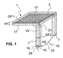
- Fig. 1 schematically shows in a perspective view a tank 1, with a housing 17, with a first central base GF1 and a first height H1 and a corresponding first volume V1, with a second tank volume 7 with a second mean base GF2, a second height H2 and a corresponding second volume V2.
- the second tank volume 7 is arranged in an edge region 21 of the first tank volume 3.
- the tank 1 can also have further second tank volumes 7, which are optionally connected to one another via a collecting line 23, which is connected to the end of the second tank volumes 7 facing away from the first tank volume 3.
- the collecting line 23 or the at least one second tank volume 7 is connected via a connecting line 10 to a reducing agent adding device 13, through which the reducing agent 2 is supplied to the exhaust gas system 14.
- the second tank volumes 7 optionally have a heater 16, which is preferably arranged in the region of the tank outlet 24 of the second tank volume 7.
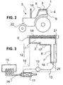
- Fig. 2 schematically shows a side view of a motor vehicle 5 with an exhaust system 14 and a body 22 with a roof 6 and a roof rail. 8
- a tank 1 for a reducing agent 2 with a first tank volume 3 in the roof area 4 of the motor vehicle 5 is arranged.
- Fig. 3 shows schematically essential to the invention details of a motor vehicle 5, in particular an internal combustion engine 15 with an attached exhaust system 14, in which at least one SCR catalyst 11 is included.
- the reducing agent 2 is supplied from a first tank volume 3 of a tank 1 and via a second tank volume 7 through a connecting line 10 to a reducing agent adding device 13 which supplies the reducing agent 2 to the exhaust gas system 14 via an injection or an injector.
- the SCR system marked in Fig. 3 by the dashed line, comprises in this embodiment, at least the two tank volumes first tank volume 3 and second tank volume 7, the reducing agent addition means 13 and the SCR catalyst 11.
- the tank 1 is arranged with a first tank volume 3 in the region of the roof 6 and in particular at least Part integrated into this roof, wherein the housing 17 of the tank 1, in particular of the first tank volume 3, is at least partially insulated by a heat insulation 18 relative to the external environment.
- the second tank volume 7 continues from an edge region 21 of the first tank volume 3 along a roof spar 8 downward and has at its lower end a tank outlet 24, in the vicinity of which, if necessary, a heater 16 is arranged.
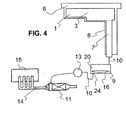
- Fig. 4 schematically shows a further view of relevant to the invention details of a motor vehicle 5. It is, similar to in Fig. 3 , a tank 1 with a first tank volume 3 arranged in a roof 6 of a motor vehicle 5 and continues with a second tank volume 7 along a roof spar 8 down. Via a connecting line 10, the second tank volume 7 is connected to a third tank volume 9, which optionally has a heater 16 in the vicinity of the tank outlet 24 within the third tank volume 9.
- the reducing agent 2 from the third tank volume 9 is added to the exhaust gas system 14 upstream of an SCR catalytic converter 11.
- the third tank volume 9 serves as a reservoir 20 for the Reduction addition device 13, which is supplied in particular by gravity 12 with reductant 2 from the other tank volumes (3, 7) that all other tank volumes (3, 7) are emptied in front of the reservoir 20.
Landscapes
- Chemical & Material Sciences (AREA)
- Engineering & Computer Science (AREA)
- Chemical Kinetics & Catalysis (AREA)
- Health & Medical Sciences (AREA)
- Toxicology (AREA)
- Combustion & Propulsion (AREA)
- Mechanical Engineering (AREA)
- General Engineering & Computer Science (AREA)
- Exhaust Gas After Treatment (AREA)
Applications Claiming Priority (1)
| Application Number | Priority Date | Filing Date | Title |
|---|---|---|---|
| DE102008022515A DE102008022515A1 (de) | 2008-05-07 | 2008-05-07 | Tank für ein Reduktionsmittel, Kraftfahrzeug mit einem Tank für ein Reduktionsmittel sowie ein Verfahren zum Betrieb einer SCR-Anlage eines Kraftfahrzeuges |
Publications (2)
| Publication Number | Publication Date |
|---|---|
| EP2116702A1 true EP2116702A1 (fr) | 2009-11-11 |
| EP2116702B1 EP2116702B1 (fr) | 2011-06-15 |
Family
ID=40929645
Family Applications (1)
| Application Number | Title | Priority Date | Filing Date |
|---|---|---|---|
| EP09156317A Not-in-force EP2116702B1 (fr) | 2008-05-07 | 2009-03-26 | Réservoir pour un moyen de réduction, véhicule automobile doté d'un réservoir pour un moyen de réduction et procédé de fonctionnement d'une installation SCR d'un véhicule automobile |
Country Status (4)
| Country | Link |
|---|---|
| US (1) | US20090277156A1 (fr) |
| EP (1) | EP2116702B1 (fr) |
| DE (1) | DE102008022515A1 (fr) |
| ES (1) | ES2366824T3 (fr) |
Cited By (2)
| Publication number | Priority date | Publication date | Assignee | Title |
|---|---|---|---|---|
| EP2868509A1 (fr) * | 2013-11-01 | 2015-05-06 | CNH Industrial Italia S.p.A. | Orifices d'accès permettant d'accéder à des réservoirs de carburant couverts d'un véhicule de travail |
| EP3025939A1 (fr) * | 2014-11-29 | 2016-06-01 | MAN Truck & Bus AG | Machine de traction dotee de deux deflecteurs de vent lateraux et reservoir de fluide intermediaire |
Families Citing this family (10)
| Publication number | Priority date | Publication date | Assignee | Title |
|---|---|---|---|---|
| US8056671B2 (en) * | 2007-10-12 | 2011-11-15 | Mazda Motor Corporation | Exhaust-gas purification device disposition structure of vehicle |
| DE102009000101A1 (de) * | 2009-01-09 | 2010-07-15 | Robert Bosch Gmbh | Tankgestaltung |
| DE102009047637A1 (de) * | 2009-12-08 | 2011-06-09 | Robert Bosch Gmbh | Entlüftungselement für Vorratstank |
| DE102010004614B4 (de) * | 2010-01-13 | 2025-03-13 | Vitesco Technologies GmbH | Vorrichtung zur Bereitstellung von flüssigem Reduktionsmittel |
| DE102010021058A1 (de) * | 2010-05-19 | 2011-11-24 | Gm Global Technology Operations Llc (N.D.Ges.D. Staates Delaware) | Vorrichtung und Verfahren zum Heizen eines Reduktionsmittels |
| DE102010024022B4 (de) * | 2010-06-16 | 2025-03-27 | Vitesco Technologies GmbH | Vorrichtung zur Förderung von flüssigem Reduktionsmittel |
| JP5356341B2 (ja) * | 2010-09-16 | 2013-12-04 | 日立建機株式会社 | 建設機械 |
| JP5336648B1 (ja) * | 2012-12-20 | 2013-11-06 | 株式会社小松製作所 | モータグレーダ |
| DE102017203298A1 (de) * | 2016-05-20 | 2017-11-23 | Röchling Automotive SE & Co. KG | Kfz-Betriebsflüssigkeitsbehälter mit integral in der Tankwandung ausgebildeter lokaler thermischer Isolation |
| FR3142507A1 (fr) * | 2022-11-25 | 2024-05-31 | Psa Automobiles Sa | Véhicule automobile equipé d’un système embarqué de captage et traitement du co2 |
Citations (5)
| Publication number | Priority date | Publication date | Assignee | Title |
|---|---|---|---|---|
| US2975797A (en) * | 1957-09-12 | 1961-03-21 | Matheney Richard | Water supply means for motor cars |
| DE2035805A1 (de) * | 1970-07-18 | 1972-01-20 | Klockner Humboldt Deutz AG, 5000 Köln | Landwirtschaftlich nutzbares Motorfahr zeug mit hydraulischer Kraftubertragungs einrichtung und einer Überschlagschutz vorrichtung |
| US3785439A (en) * | 1972-02-09 | 1974-01-15 | Leroy Britt | Tractor canopy sprinkler system |
| US6151907A (en) * | 1999-09-29 | 2000-11-28 | Hale; Roger G. | Misting system for vehicle |
| EP1388648A1 (fr) * | 2002-08-09 | 2004-02-11 | Ford Global Technologies, LLC | Procédé et dispositif pour la protection contre legel d'un agent réducteur liquide pour NOx dans un véhicule |
Family Cites Families (10)
| Publication number | Priority date | Publication date | Assignee | Title |
|---|---|---|---|---|
| US2151097A (en) * | 1935-09-09 | 1939-03-21 | Evans Prod Co | Means and method for cooling vehicle bodies |
| US3696979A (en) * | 1971-04-28 | 1972-10-10 | Keith Duane Erickson | Car top carrier |
| US4012062A (en) * | 1975-10-16 | 1977-03-15 | Lawrence Peska Associates, Inc. | Sanding device for a motor vehicle |
| CA2088713C (fr) * | 1992-02-24 | 1999-11-16 | Hans Thomas Hug | Nettoyage des gaz d'echappement des installations de combustion |
| DE19728343C5 (de) * | 1997-07-03 | 2013-02-21 | Robert Bosch Gmbh | Verfahren und Vorrichtung zur selektiven katalytischen NOx-Reduktion |
| WO2005073527A1 (fr) * | 2004-02-02 | 2005-08-11 | Nissan Diesel Motor Co., Ltd. | Dispositif de purification des gaz d’echappement d’un moteur á combustion interne |
| US20080169033A1 (en) * | 2005-03-14 | 2008-07-17 | Inergy Auto. Systems Research (Societe Anonyme) | Fuel Tank With Low Profile Fuel Reservoir |
| DE202006010615U1 (de) * | 2005-09-26 | 2006-10-26 | Dbk David + Baader Gmbh | Tanksystem mit einem Haupttank und einer Abschmelzvorrichtung mit Schmelztank |
| US20090261107A1 (en) * | 2005-12-23 | 2009-10-22 | Thorsten Allgeier | Motor vehicle with a gas tank |
| US20090127265A1 (en) * | 2006-04-27 | 2009-05-21 | Volvo Lastvagnar Ab | Liquid receptacle for a vehicle |
-
2008
- 2008-05-07 DE DE102008022515A patent/DE102008022515A1/de not_active Withdrawn
-
2009
- 2009-03-26 EP EP09156317A patent/EP2116702B1/fr not_active Not-in-force
- 2009-03-26 ES ES09156317T patent/ES2366824T3/es active Active
- 2009-05-07 US US12/437,047 patent/US20090277156A1/en not_active Abandoned
Patent Citations (5)
| Publication number | Priority date | Publication date | Assignee | Title |
|---|---|---|---|---|
| US2975797A (en) * | 1957-09-12 | 1961-03-21 | Matheney Richard | Water supply means for motor cars |
| DE2035805A1 (de) * | 1970-07-18 | 1972-01-20 | Klockner Humboldt Deutz AG, 5000 Köln | Landwirtschaftlich nutzbares Motorfahr zeug mit hydraulischer Kraftubertragungs einrichtung und einer Überschlagschutz vorrichtung |
| US3785439A (en) * | 1972-02-09 | 1974-01-15 | Leroy Britt | Tractor canopy sprinkler system |
| US6151907A (en) * | 1999-09-29 | 2000-11-28 | Hale; Roger G. | Misting system for vehicle |
| EP1388648A1 (fr) * | 2002-08-09 | 2004-02-11 | Ford Global Technologies, LLC | Procédé et dispositif pour la protection contre legel d'un agent réducteur liquide pour NOx dans un véhicule |
Cited By (3)
| Publication number | Priority date | Publication date | Assignee | Title |
|---|---|---|---|---|
| EP2868509A1 (fr) * | 2013-11-01 | 2015-05-06 | CNH Industrial Italia S.p.A. | Orifices d'accès permettant d'accéder à des réservoirs de carburant couverts d'un véhicule de travail |
| EP3025939A1 (fr) * | 2014-11-29 | 2016-06-01 | MAN Truck & Bus AG | Machine de traction dotee de deux deflecteurs de vent lateraux et reservoir de fluide intermediaire |
| RU2706871C2 (ru) * | 2014-11-29 | 2019-11-21 | Ман Трак Унд Бас Аг | Тягач с двумя боковыми ветроотражателями и находящимся между ними баком для текучей среды |
Also Published As
| Publication number | Publication date |
|---|---|
| EP2116702B1 (fr) | 2011-06-15 |
| DE102008022515A1 (de) | 2009-11-12 |
| US20090277156A1 (en) | 2009-11-12 |
| ES2366824T3 (es) | 2011-10-25 |
Similar Documents
| Publication | Publication Date | Title |
|---|---|---|
| EP2116702B1 (fr) | Réservoir pour un moyen de réduction, véhicule automobile doté d'un réservoir pour un moyen de réduction et procédé de fonctionnement d'une installation SCR d'un véhicule automobile | |
| DE10335265B4 (de) | Kraftfahrzeug mit spezieller Anordnung eines Kraftstofftanks, Vorschalldämpfers und Reduktionsmitteltanks | |
| EP1841956B1 (fr) | Procede et dispositif pour le post-traitement de gaz d'echappement | |
| DE102013204189B4 (de) | Mischsystem | |
| EP2379854B1 (fr) | Elément de type canal pour la compensation de gel | |
| EP2473721B1 (fr) | Dispoitif d'ajout d'un agent réducteur avec un élément de compensation | |
| WO2002025075A1 (fr) | Dispositif pour le dosage d'un agent de reduction | |
| DE112011101560T5 (de) | Invertiert angeordneter Abgasbehandlungsinjektor | |
| DE102014206339A1 (de) | Reduktor-abgabeeinheit zur selektiven katalytischen reduktion bei fahrzeugen mit reduktionsmittel-erwärmung | |
| DE102011120457A1 (de) | Einspritzvorrichtung zur Zugabe eines flüssigen Additivs | |
| EP2126298B1 (fr) | Dispositif de dosage d'agent de réduction | |
| DE102020117933A1 (de) | Integrierter basisfilter für einen def-verteiler | |
| DE102014212544A1 (de) | Heizung | |
| EP1554485B1 (fr) | Installation d'alimentation en carburant d'un moteur a combustion interne | |
| DE102010021301A1 (de) | Kraftfahrzeug mit einem Kraftstofftank und einem Zusatztank | |
| DE102011120221B4 (de) | Mischer für eine Abgasanlage und Abgasanlage | |
| DE102009045721A1 (de) | Tank für ein flüssiges Reduktionsmittel | |
| WO2013079509A1 (fr) | Système de post-traitement des gaz d'échappement et procédé d'introduction d'un agent de réduction dans un canal pour gaz d'échappement d'un moteur à combustion interne | |
| EP2294293B1 (fr) | Procede de post-traitement des gaz d'echappement d'un moteur a combustion interne | |
| DE102010039060A1 (de) | Versorgungssystem für Brennkraftmaschinen mit isoliertem Vorratsbehälter | |
| DE102009036260A1 (de) | Vorratsbehälter | |
| DE102013109805B4 (de) | Vorrichtung zur Bereitstellung eines flüssigen Additivs | |
| EP2116701A1 (fr) | Dispositif de préparation d'une solution de moyen de réduction dans un système de gaz d'échappement et système de gaz d'échappement correspondant | |
| EP3212906A1 (fr) | Ensemble de pompage pour le déplacement d'un liquide | |
| DE102020121169A1 (de) | Schlauchanschluss, Stecksystem und System zum Verbinden von einer ersten und einer zweiten Dosierstelle |
Legal Events
| Date | Code | Title | Description |
|---|---|---|---|
| PUAI | Public reference made under article 153(3) epc to a published international application that has entered the european phase |
Free format text: ORIGINAL CODE: 0009012 |
|
| AK | Designated contracting states |
Kind code of ref document: A1 Designated state(s): AT BE BG CH CY CZ DE DK EE ES FI FR GB GR HR HU IE IS IT LI LT LU LV MC MK MT NL NO PL PT RO SE SI SK TR |
|
| AX | Request for extension of the european patent |
Extension state: AL BA RS |
|
| 17P | Request for examination filed |
Effective date: 20100312 |
|
| 17Q | First examination report despatched |
Effective date: 20100414 |
|
| AKX | Designation fees paid |
Designated state(s): DE ES FR GB IT |
|
| GRAP | Despatch of communication of intention to grant a patent |
Free format text: ORIGINAL CODE: EPIDOSNIGR1 |
|
| GRAS | Grant fee paid |
Free format text: ORIGINAL CODE: EPIDOSNIGR3 |
|
| GRAA | (expected) grant |
Free format text: ORIGINAL CODE: 0009210 |
|
| AK | Designated contracting states |
Kind code of ref document: B1 Designated state(s): DE ES FR GB IT |
|
| REG | Reference to a national code |
Ref country code: GB Ref legal event code: FG4D Free format text: NOT ENGLISH |
|
| REG | Reference to a national code |
Ref country code: DE Ref legal event code: R096 Ref document number: 502009000783 Country of ref document: DE Effective date: 20110728 |
|
| REG | Reference to a national code |
Ref country code: ES Ref legal event code: FG2A Ref document number: 2366824 Country of ref document: ES Kind code of ref document: T3 Effective date: 20111025 |
|
| PLBE | No opposition filed within time limit |
Free format text: ORIGINAL CODE: 0009261 |
|
| STAA | Information on the status of an ep patent application or granted ep patent |
Free format text: STATUS: NO OPPOSITION FILED WITHIN TIME LIMIT |
|
| PGFP | Annual fee paid to national office [announced via postgrant information from national office to epo] |
Ref country code: FR Payment date: 20120405 Year of fee payment: 4 |
|
| 26N | No opposition filed |
Effective date: 20120316 |
|
| PGFP | Annual fee paid to national office [announced via postgrant information from national office to epo] |
Ref country code: IT Payment date: 20120331 Year of fee payment: 4 |
|
| REG | Reference to a national code |
Ref country code: DE Ref legal event code: R097 Ref document number: 502009000783 Country of ref document: DE Effective date: 20120316 |
|
| PGFP | Annual fee paid to national office [announced via postgrant information from national office to epo] |
Ref country code: DE Payment date: 20120411 Year of fee payment: 4 |
|
| PGFP | Annual fee paid to national office [announced via postgrant information from national office to epo] |
Ref country code: ES Payment date: 20120321 Year of fee payment: 4 |
|
| GBPC | Gb: european patent ceased through non-payment of renewal fee |
Effective date: 20130326 |
|
| REG | Reference to a national code |
Ref country code: FR Ref legal event code: ST Effective date: 20131129 |
|
| REG | Reference to a national code |
Ref country code: DE Ref legal event code: R119 Ref document number: 502009000783 Country of ref document: DE Effective date: 20131001 |
|
| PG25 | Lapsed in a contracting state [announced via postgrant information from national office to epo] |
Ref country code: FR Free format text: LAPSE BECAUSE OF NON-PAYMENT OF DUE FEES Effective date: 20130402 Ref country code: DE Free format text: LAPSE BECAUSE OF NON-PAYMENT OF DUE FEES Effective date: 20131001 Ref country code: GB Free format text: LAPSE BECAUSE OF NON-PAYMENT OF DUE FEES Effective date: 20130326 |
|
| PG25 | Lapsed in a contracting state [announced via postgrant information from national office to epo] |
Ref country code: IT Free format text: LAPSE BECAUSE OF NON-PAYMENT OF DUE FEES Effective date: 20130326 |
|
| REG | Reference to a national code |
Ref country code: ES Ref legal event code: FD2A Effective date: 20140606 |
|
| PG25 | Lapsed in a contracting state [announced via postgrant information from national office to epo] |
Ref country code: ES Free format text: LAPSE BECAUSE OF NON-PAYMENT OF DUE FEES Effective date: 20130327 |