EP2116703B1 - Verbrennungsmotor und steuervorrichtung für einen verbrennungsmotor - Google Patents
Verbrennungsmotor und steuervorrichtung für einen verbrennungsmotor Download PDFInfo
- Publication number
- EP2116703B1 EP2116703B1 EP08711138A EP08711138A EP2116703B1 EP 2116703 B1 EP2116703 B1 EP 2116703B1 EP 08711138 A EP08711138 A EP 08711138A EP 08711138 A EP08711138 A EP 08711138A EP 2116703 B1 EP2116703 B1 EP 2116703B1
- Authority
- EP
- European Patent Office
- Prior art keywords
- catalyst
- exhaust
- upstream side
- valve
- passage
- Prior art date
- Legal status (The legal status is an assumption and is not a legal conclusion. Google has not performed a legal analysis and makes no representation as to the accuracy of the status listed.)
- Not-in-force
Links
Images



Classifications
-
- F—MECHANICAL ENGINEERING; LIGHTING; HEATING; WEAPONS; BLASTING
- F01—MACHINES OR ENGINES IN GENERAL; ENGINE PLANTS IN GENERAL; STEAM ENGINES
- F01N—GAS-FLOW SILENCERS OR EXHAUST APPARATUS FOR MACHINES OR ENGINES IN GENERAL; GAS-FLOW SILENCERS OR EXHAUST APPARATUS FOR INTERNAL-COMBUSTION ENGINES
- F01N13/00—Exhaust or silencing apparatus characterised by constructional features
- F01N13/009—Exhaust or silencing apparatus characterised by constructional features having two or more separate purifying devices arranged in series
-
- F—MECHANICAL ENGINEERING; LIGHTING; HEATING; WEAPONS; BLASTING
- F01—MACHINES OR ENGINES IN GENERAL; ENGINE PLANTS IN GENERAL; STEAM ENGINES
- F01N—GAS-FLOW SILENCERS OR EXHAUST APPARATUS FOR MACHINES OR ENGINES IN GENERAL; GAS-FLOW SILENCERS OR EXHAUST APPARATUS FOR INTERNAL-COMBUSTION ENGINES
- F01N3/00—Exhaust or silencing apparatus having means for purifying, rendering innocuous, or otherwise treating exhaust
- F01N3/08—Exhaust or silencing apparatus having means for purifying, rendering innocuous, or otherwise treating exhaust for rendering innocuous
- F01N3/10—Exhaust or silencing apparatus having means for purifying, rendering innocuous, or otherwise treating exhaust for rendering innocuous by thermal or catalytic conversion of noxious components of exhaust
- F01N3/18—Exhaust or silencing apparatus having means for purifying, rendering innocuous, or otherwise treating exhaust for rendering innocuous by thermal or catalytic conversion of noxious components of exhaust characterised by methods of operation; Control
- F01N3/20—Exhaust or silencing apparatus having means for purifying, rendering innocuous, or otherwise treating exhaust for rendering innocuous by thermal or catalytic conversion of noxious components of exhaust characterised by methods of operation; Control specially adapted for catalytic conversion
- F01N3/2053—By-passing catalytic reactors, e.g. to prevent overheating
-
- F—MECHANICAL ENGINEERING; LIGHTING; HEATING; WEAPONS; BLASTING
- F02—COMBUSTION ENGINES; HOT-GAS OR COMBUSTION-PRODUCT ENGINE PLANTS
- F02D—CONTROLLING COMBUSTION ENGINES
- F02D41/00—Electrical control of supply of combustible mixture or its constituents
- F02D41/0025—Controlling engines characterised by use of non-liquid fuels, pluralities of fuels, or non-fuel substances added to the combustible mixtures
- F02D41/0047—Controlling exhaust gas recirculation [EGR]
- F02D41/0065—Specific aspects of external EGR control
-
- F—MECHANICAL ENGINEERING; LIGHTING; HEATING; WEAPONS; BLASTING
- F02—COMBUSTION ENGINES; HOT-GAS OR COMBUSTION-PRODUCT ENGINE PLANTS
- F02M—SUPPLYING COMBUSTION ENGINES IN GENERAL WITH COMBUSTIBLE MIXTURES OR CONSTITUENTS THEREOF
- F02M26/00—Engine-pertinent apparatus for adding exhaust gases to combustion-air, main fuel or fuel-air mixture, e.g. by exhaust gas recirculation [EGR] systems
- F02M26/02—EGR systems specially adapted for supercharged engines
- F02M26/04—EGR systems specially adapted for supercharged engines with a single turbocharger
- F02M26/05—High pressure loops, i.e. wherein recirculated exhaust gas is taken out from the exhaust system upstream of the turbine and reintroduced into the intake system downstream of the compressor
-
- F—MECHANICAL ENGINEERING; LIGHTING; HEATING; WEAPONS; BLASTING
- F02—COMBUSTION ENGINES; HOT-GAS OR COMBUSTION-PRODUCT ENGINE PLANTS
- F02M—SUPPLYING COMBUSTION ENGINES IN GENERAL WITH COMBUSTIBLE MIXTURES OR CONSTITUENTS THEREOF
- F02M26/00—Engine-pertinent apparatus for adding exhaust gases to combustion-air, main fuel or fuel-air mixture, e.g. by exhaust gas recirculation [EGR] systems
- F02M26/13—Arrangement or layout of EGR passages, e.g. in relation to specific engine parts or for incorporation of accessories
- F02M26/14—Arrangement or layout of EGR passages, e.g. in relation to specific engine parts or for incorporation of accessories in relation to the exhaust system
- F02M26/15—Arrangement or layout of EGR passages, e.g. in relation to specific engine parts or for incorporation of accessories in relation to the exhaust system in relation to engine exhaust purifying apparatus
-
- F—MECHANICAL ENGINEERING; LIGHTING; HEATING; WEAPONS; BLASTING
- F02—COMBUSTION ENGINES; HOT-GAS OR COMBUSTION-PRODUCT ENGINE PLANTS
- F02M—SUPPLYING COMBUSTION ENGINES IN GENERAL WITH COMBUSTIBLE MIXTURES OR CONSTITUENTS THEREOF
- F02M26/00—Engine-pertinent apparatus for adding exhaust gases to combustion-air, main fuel or fuel-air mixture, e.g. by exhaust gas recirculation [EGR] systems
- F02M26/13—Arrangement or layout of EGR passages, e.g. in relation to specific engine parts or for incorporation of accessories
- F02M26/42—Arrangement or layout of EGR passages, e.g. in relation to specific engine parts or for incorporation of accessories having two or more EGR passages; EGR systems specially adapted for engines having two or more cylinders
- F02M26/44—Arrangement or layout of EGR passages, e.g. in relation to specific engine parts or for incorporation of accessories having two or more EGR passages; EGR systems specially adapted for engines having two or more cylinders in which a main EGR passage is branched into multiple passages
-
- F—MECHANICAL ENGINEERING; LIGHTING; HEATING; WEAPONS; BLASTING
- F01—MACHINES OR ENGINES IN GENERAL; ENGINE PLANTS IN GENERAL; STEAM ENGINES
- F01N—GAS-FLOW SILENCERS OR EXHAUST APPARATUS FOR MACHINES OR ENGINES IN GENERAL; GAS-FLOW SILENCERS OR EXHAUST APPARATUS FOR INTERNAL-COMBUSTION ENGINES
- F01N2340/00—Dimensional characteristics of the exhaust system, e.g. length, diameter or volume of the exhaust apparatus; Spatial arrangements of exhaust apparatuses
- F01N2340/06—Arrangement of the exhaust apparatus relative to the turbine of a turbocharger
-
- F—MECHANICAL ENGINEERING; LIGHTING; HEATING; WEAPONS; BLASTING
- F01—MACHINES OR ENGINES IN GENERAL; ENGINE PLANTS IN GENERAL; STEAM ENGINES
- F01N—GAS-FLOW SILENCERS OR EXHAUST APPARATUS FOR MACHINES OR ENGINES IN GENERAL; GAS-FLOW SILENCERS OR EXHAUST APPARATUS FOR INTERNAL-COMBUSTION ENGINES
- F01N2410/00—By-passing, at least partially, exhaust from inlet to outlet of apparatus, to atmosphere or to other device
- F01N2410/06—By-passing, at least partially, exhaust from inlet to outlet of apparatus, to atmosphere or to other device at cold starting
-
- F—MECHANICAL ENGINEERING; LIGHTING; HEATING; WEAPONS; BLASTING
- F02—COMBUSTION ENGINES; HOT-GAS OR COMBUSTION-PRODUCT ENGINE PLANTS
- F02B—INTERNAL-COMBUSTION PISTON ENGINES; COMBUSTION ENGINES IN GENERAL
- F02B37/00—Engines characterised by provision of pumps driven at least for part of the time by exhaust
- F02B37/12—Control of the pumps
- F02B37/18—Control of the pumps by bypassing exhaust from the inlet to the outlet of turbine or to the atmosphere
-
- F—MECHANICAL ENGINEERING; LIGHTING; HEATING; WEAPONS; BLASTING
- F02—COMBUSTION ENGINES; HOT-GAS OR COMBUSTION-PRODUCT ENGINE PLANTS
- F02D—CONTROLLING COMBUSTION ENGINES
- F02D41/00—Electrical control of supply of combustible mixture or its constituents
- F02D41/0025—Controlling engines characterised by use of non-liquid fuels, pluralities of fuels, or non-fuel substances added to the combustible mixtures
- F02D41/0047—Controlling exhaust gas recirculation [EGR]
- F02D41/0065—Specific aspects of external EGR control
- F02D2041/0067—Determining the EGR temperature
-
- F—MECHANICAL ENGINEERING; LIGHTING; HEATING; WEAPONS; BLASTING
- F02—COMBUSTION ENGINES; HOT-GAS OR COMBUSTION-PRODUCT ENGINE PLANTS
- F02D—CONTROLLING COMBUSTION ENGINES
- F02D41/00—Electrical control of supply of combustible mixture or its constituents
- F02D41/02—Circuit arrangements for generating control signals
- F02D41/04—Introducing corrections for particular operating conditions
- F02D41/12—Introducing corrections for particular operating conditions for deceleration
- F02D41/123—Introducing corrections for particular operating conditions for deceleration the fuel injection being cut-off
-
- F—MECHANICAL ENGINEERING; LIGHTING; HEATING; WEAPONS; BLASTING
- F02—COMBUSTION ENGINES; HOT-GAS OR COMBUSTION-PRODUCT ENGINE PLANTS
- F02M—SUPPLYING COMBUSTION ENGINES IN GENERAL WITH COMBUSTIBLE MIXTURES OR CONSTITUENTS THEREOF
- F02M26/00—Engine-pertinent apparatus for adding exhaust gases to combustion-air, main fuel or fuel-air mixture, e.g. by exhaust gas recirculation [EGR] systems
- F02M26/13—Arrangement or layout of EGR passages, e.g. in relation to specific engine parts or for incorporation of accessories
- F02M26/22—Arrangement or layout of EGR passages, e.g. in relation to specific engine parts or for incorporation of accessories with coolers in the recirculation passage
- F02M26/23—Layout, e.g. schematics
- F02M26/25—Layout, e.g. schematics with coolers having bypasses
-
- F—MECHANICAL ENGINEERING; LIGHTING; HEATING; WEAPONS; BLASTING
- F02—COMBUSTION ENGINES; HOT-GAS OR COMBUSTION-PRODUCT ENGINE PLANTS
- F02M—SUPPLYING COMBUSTION ENGINES IN GENERAL WITH COMBUSTIBLE MIXTURES OR CONSTITUENTS THEREOF
- F02M26/00—Engine-pertinent apparatus for adding exhaust gases to combustion-air, main fuel or fuel-air mixture, e.g. by exhaust gas recirculation [EGR] systems
- F02M26/45—Sensors specially adapted for EGR systems
- F02M26/46—Sensors specially adapted for EGR systems for determining the characteristics of gases, e.g. composition
- F02M26/47—Sensors specially adapted for EGR systems for determining the characteristics of gases, e.g. composition the characteristics being temperatures, pressures or flow rates
-
- Y—GENERAL TAGGING OF NEW TECHNOLOGICAL DEVELOPMENTS; GENERAL TAGGING OF CROSS-SECTIONAL TECHNOLOGIES SPANNING OVER SEVERAL SECTIONS OF THE IPC; TECHNICAL SUBJECTS COVERED BY FORMER USPC CROSS-REFERENCE ART COLLECTIONS [XRACs] AND DIGESTS
- Y02—TECHNOLOGIES OR APPLICATIONS FOR MITIGATION OR ADAPTATION AGAINST CLIMATE CHANGE
- Y02T—CLIMATE CHANGE MITIGATION TECHNOLOGIES RELATED TO TRANSPORTATION
- Y02T10/00—Road transport of goods or passengers
- Y02T10/10—Internal combustion engine [ICE] based vehicles
- Y02T10/12—Improving ICE efficiencies
-
- Y—GENERAL TAGGING OF NEW TECHNOLOGICAL DEVELOPMENTS; GENERAL TAGGING OF CROSS-SECTIONAL TECHNOLOGIES SPANNING OVER SEVERAL SECTIONS OF THE IPC; TECHNICAL SUBJECTS COVERED BY FORMER USPC CROSS-REFERENCE ART COLLECTIONS [XRACs] AND DIGESTS
- Y02—TECHNOLOGIES OR APPLICATIONS FOR MITIGATION OR ADAPTATION AGAINST CLIMATE CHANGE
- Y02T—CLIMATE CHANGE MITIGATION TECHNOLOGIES RELATED TO TRANSPORTATION
- Y02T10/00—Road transport of goods or passengers
- Y02T10/10—Internal combustion engine [ICE] based vehicles
- Y02T10/40—Engine management systems
Definitions
- the present invention relates to an internal combustion engine having a turbocharger and catalysts for purifying exhaust gases, and a control system for the internal combustion engine.
- JP 2005-171932 A discloses an exhaust gas purifying apparatus for an internal combustion engine having a turbocharger.
- a catalyst for purifying exhaust gases is disposed upstream of a turbine of the turbocharger in an exhaust passage of the engine, and a bypass passage bypassing the catalyst is provided.
- the exhaust gases passing through the catalyst are supplied to the turbine.
- the exhaust gases passing through the bypass passage are supplied to the turbine.
- the exhaust gases passing through the catalyst are supplied to the turbine in the state where an exhaust gas temperature is low, thereby maintaining good exhaust characteristics.
- the exhaust gases bypassing the catalyst are supplied to the turbine, thereby preventing drivability of the engine from deteriorating.
- JP 2006-220046 A on which the preamble of claim 1 is based, suggests that the connecting portion between the catalyst bypass passage and the exhaust main passage locates on the same portion or a slightly downstream portion of the connecting portion between the EGR passage and the exhaust system ( FIG. 1 ). According to this configuration, a large amount of high temperature exhaust gases flowing out from the catalyst are recirculated to the intake system through the EGR passage, for example after warming-up of the engine. Accordingly, the temperature of EGR gases becomes very high, which may degrade the NOx reduction effect of the EGR.
- JP 11-229973 A a catalyst 4 and first and second EGR passages 6, 9 are shown, but no catalyst bypass.
- P 2002/349241 which corresponds to EP 1 260 684 A2 shows in figures 1 and 2 a diesel particulate filter (DPF 13) in an exhaust passage upstream of a turbine 81.
- the bypass is provided with a bypass valve 102.
- An EGR passage 9 is connected to the branching point 9 between the bypass (having valve 102) and the exhaust passage (having DPF 13) on the upstream side of the DPF 13.
- JP 09-209742 A shows an exhaust passage 13 provided with the pre-catalyst 31, and a bypass 43 bypassing the pre-catalyst 31.
- a bypass valve 44 is provided with similar position as in D1 and D3, upstream of a connection point between the exhaust passage 13 (having the pre-catalyst 31) and the bypass (having the valve 44).
- JP 2006-046288 A an exhaust passage 4 is provided with a catalyst 5 and a bypass 6 bypassing the catalyst 5.
- a switching valve 4a is provided in a branching point of the passage (having the catalyst 5 therein) and the bypass i.e. upstream of the catalyst 5.
- JP 2004-019624 A a pre-catalyst 17 is provided upstream of a turbine 15b.
- An EGR passage 18 is provided with an EGR cooler 20, and an EGR valve 19 downstream of the EGR cooler 20, i.e. on the opposite side of the connecting point between the exhaust passage and the EGR passage 18 with respect to the EGR cooler 20.
- the exhaust gas recirculation passage is provided between an upstream side of the catalyst and the intake system of the engine. Accordingly, the exhaust gas temperature is low before completion of the warming-up of the engine, and a temperature of the recirculated exhaust gases is also low. Consequently, a time period necessary for completing the warming-up tends to become long. Further, when the engine is accelerated before completion of the warming-up of the engine, there is a possibility that unburnt fuel components adhere to the exhaust gas recirculation passage or the exhaust gas recirculation control valve, which may reduce an effective cross section area of the exhaust gas recirculation passage and/or cause sticking of the exhaust gas recirculation control valve.
- the present invention was made contemplating this point, and a first object of the present invention is to provide an internal combustion engine, which can prevent the unburnt fuel components from flowing into the exhaust gas recirculation passage and raise a temperature of the exhaust gases recirculated to the intake system before completion of the warming-up of the engine.
- a second object of the present invention is to provide a control system for an internal combustion engine which appropriately changes flowing passages of the exhaust gases recirculated to the intake system, thereby obtaining good exhaust characteristics of the engine.
- the present invention provides internal combustion engine having a turbocharger (9) in accordance with claim 1.
- the internal combustion engine is characterized by including a turbine (9a) of the turbocharger located in an exhaust system (8) of the engine, the upstream side catalyst (11) located upstream of the turbine (9a), a catalyst bypass passage (12) bypassing the upstream side catalyst (11), a catalyst bypass passage on/off valve (13) for opening and closing the catalyst bypass passage (12), and a first exhaust gas recirculation passage (25) for recirculating a part of exhaust gases from a portion between the upstream side catalyst (11) and the turbine (9a) to an intake system (7) of the engine, characterized in that said catalyst by pass passage out off valve (13) is disposed at a connecting portion located downstream of the upstream side catalyst between said catalyst bypass passage and said exhaust pipe, wherein said first exhaust gas recirculation passage is connected to said exhaust system downstream of said catalyst bypass passage out off valve.
- the exhaust gases discharged from the engine passes through the upstream side catalyst in a state where the catalyst bypass passage on/off valve is closed, and a part of exhaust gases discharged from the upstream side catalyst is recirculated to the intake system through the exhaust gas recirculation passage. Further, the remaining most part of the exhaust gases is supplied to the turbine.
- unburnt fuel components burn in the upstream side catalyst to raise the temperature of the exhaust gases by closing the catalyst bypass passage on/off valve, and the exhaust gases of the raised temperature is recirculated to the intake system.
- the warming-up of the engine is accelerated and the unburnt fuel components are prevented from flowing into the exhaust gas recirculation passage, which makes it possible to avoid reduction of the effective cross section area of the exhaust gas recirculation passage or sticking of the exhaust gas recirculation control valve. Further, after completion of the warming-up of the engine, thermal deterioration and increase in the pressure loss of the upstream side catalyst are suppressed by opening the catalyst bypass passage on/off valve, thereby preventing the temperature of the recirculated exhaust gases from becoming too high.
- the present invention provides an internal combustion engine having a turbocharger (9).
- the internal combustion engine is characterized by including a turbine (9a) of the turbocharger in an exhaust system (8) of the engine, a upstream side catalyst (11) disposed upstream side of the turbine (9a), a catalyst bypass passage (12) bypassing the upstream side catalyst (11), a catalyst bypass passage on/off valve (13) for opening and closing the catalyst bypass passage (12), a first exhaust gas recirculation passage (25a, 25b) for recirculating a part of exhaust gases from a portion between the upstream side catalyst (11) and the turbines (9a) to an intake system (7) of the engine, a second exhaust gas recirculation passage (31, 25a) for recirculating a part of exhaust gases from an upstream side of the upstream side catalyst (11) to the intake system, and a switching valve (32) for switching between the first exhaust gas recirculation passage and the second exhaust gas recirculation passage.
- the warming-up of the engine is accelerated and the unburnt fuel components are prevented form flowing into the exhaust gas recirculation passage, which makes it possible to avoid reduction of the effective cross section area of the exhaust gas recirculation passage or sticking of the exhaust gas recirculation control valve. Further, after completion of the warming-up of the engine, thermal deterioration and increase in the pressure loss of the upstream side catalyst are suppressed by opening the catalyst bypass passage on/off valve, thereby preventing the temperature of the recirculated exhaust gases from becoming too high.
- the temperature of the recirculated exhaust gases is prevented from becoming too high while purifying the exhaust gases with the upstream side catalyst.
- the internal combustion engine further includes a downstream side catalyst (33) disposed downstream of the turbine (9a).
- a downstream side catalyst (33) disposed downstream of the turbine (9a).
- the internal combustion engine further includes a turbine bypass passage (14) bypassing the turbine (9a) and a turbine bypass passage on/off valve (15) for opening and closing the turbine bypass passage (14), wherein the downstream side catalyst (33) is located downstream of a connecting portion at which the exhaust passage (8) and the turbine bypass passage (14) are connected downstream of the turbine (9a).
- the internal combustion engine further includes a particulate filter (34) disposed downstream of the downstream side catalyst (33).
- a particulate filter disposed downstream of the downstream side catalyst (33).
- the internal combustion engine further includes a lean NOx catalyst (35) disposed downstream of the particulate filter (34).
- a lean NOx catalyst 35) disposed downstream of the particulate filter (34).
- the downstream side catalyst (33) is a three-way catalyst added with a NOx trapping agent or an oxidation catalyst added with a hydrocarbon adsorbent.
- the downstream side catalyst traps NOx to secure a high NOx trapping rate even if the upstream side catalyst does not sufficiently trap NOx in a high-load operating condition of the engine.
- the oxidation catalyst added with the hydrocarbon adsorbent oxidation of hydrocarbon and CO can be accelerated by making exhaust gases bypass the upstream side catalyst to directly flow into the downstream side catalyst when the exhaust gas temperature is high.
- the upstream side catalyst (11) is any one of an oxidation catalyst added with a hydrocarbon adsorbent, a three-way catalyst added with a NOx trapping agent, and a three-way catalyst added with a NOx trapping agent and a hydrocarbon adsorbent.
- NOx trapping agent By adding the NOx trapping agent to the upstream side catalyst, NOx can be trapped immediately after starting of the engine, and the trapped NOx can be reduced by enriching the air-fuel ratio. Further, by adding the hydrocarbon adsorbent, hydrocarbon is adsorbed immediately after starting of the engine, thereby significantly reducing an emission amount of hydrocarbon.
- the NOx trapping agent is ceria
- the hydrocarbon adsorbent is zeolite.
- ceria as the NOx trapping agent, NOx can be trapped at a lower temperature compared with the case that alkali metal or the like is used.
- zeolite as the hydrocarbon adsorbent, sufficient adsorbing capability can be obtained when the temperature of exhaust gases is high.
- the present invention provides a control system for an internal combustion engine in accordance with claim 10.
- the engine includes a turbo charger (9), a turbine (9a) of the turbocharger in an exhaust system (8) of the engine, a upstream side catalyst (11) disposed upstream side of the turbine (9a), a catalyst bypass passage (12) bypassing the upstream side catalyst (11), a catalyst bypass passage on/off valve (13) for opening and closing the catalyst bypass passage (12), a first exhaust gas recirculation passage (25a, 25b) for recirculating a part of exhaust gases from a portion between the upstream side catalyst (11) and the turbines (9a) to an intake system (7) of the engine, a second exhaust gas recirculation passage (31, 25a) for recirculating a part of exhaust gases from an upstream side of the upstream side catalyst (11) to the intake system, a switching valve (32) for switching between the first exhaust gas recirculation passage and the second exhaust gas recirculation passage, wherein said catalyst bypass passage out off valve is disposed at
- the control system is characterized by closing the catalyst bypass passage on/off valve (13) and switching the switching valve (32) to a state of connecting the first exhaust gas recirculation passage (25a, 25b) when a temperature (TW) of the engine is low, wherein the switching valve (32) is switched to the other state of connecting the second exhaust gas recirculation passage (31, 25a), when a temperature (TEGR) of exhaust gases recirculated through the first exhaust gas recirculation passage exceeds a predetermined exhaust gas temperature (TEGRX).
- TEGR temperature
- the catalyst bypass passage on/off valve is closed, and the switching valve is switched to the state of connecting the first exhaust gas recirculation passage, wherein if the temperature of exhaust gases recirculated through the first exhaust gas recirculation passage exceeds the predetermined exhaust gas temperature, the switching valve is switched to the state of connecting the second exhaust gas recirculation passage.
- the exhaust gases discharged from the engine passes through the upstream side catalyst, and a part of exhaust gases discharged from the upstream side catalyst is recirculated through the first exhaust gas recirculation passage to the intake system.
- the catalyst bypass passage on/off valve is closed. Therefore, the unburnt fuel components burn in the upstream side catalyst to raise the temperature of the exhaust gases by closing the catalyst bypass passage on/off valve, and the exhaust gases of the raised temperature is recirculated to the intake system. Consequently, the warming-up of the engine is accelerated and the unburnt fuel components are prevented form flowing into the exhaust gas recirculation passage, which makes it possible to avoid reduction of the effective cross section area of the exhaust gas recirculation passage or sticking of the exhaust gas recirculation control valve.
- the switching valve is switched to the state of connecting the second exhaust gas recirculation passage side if the temperature of the recirculated exhaust gases exceeds the predetermined exhaust gas temperature. Therefore, the temperature of the recirculated exhaust gases is prevented from becoming too high while purifying the exhaust gases with the upstream side catalyst. Consequently, good exhaust characteristic can be obtained.
- the catalyst bypass passage on/off valve (13) is closed when the temperature (TW) of the engine is low.
- the exhaust gases discharged from the engine passes through the upstream side catalyst, and a part of the exhaust gases discharged from the upstream side catalyst is recirculated through the exhaust gas recirculation passage to the intake system, while the remaining most part of the exhaust gases is supplied to the turbine. Therefore, the unburnt fuel components burn in the upstream side catalyst to raise the temperature of the exhaust gases, and the exhaust gases of the raised temperature is recirculated to the intake system. Consequently, the warming-up of the engine is accelerated and the unburnt fuel components are prevented from flowing into the exhaust gas recirculation passage, which makes it possible to avoid reduction of the effective cross section area of the exhaust gas recirculation passage or sticking of the exhaust gas recirculation control valve.
- the catalyst bypass passage on/off valve (13) is closed when a temperature (TPTC) of the upstream side catalyst is equal to or less than a predetermined catalyst temperature (TPTCX).
- FIG. 1 is a schematic diagram showing a configuration of an internal combustion engine and a control system therefor according to one embodiment of the present invention.
- the internal combustion engine 1 (hereinafter referred to as “engine") is a diesel engine wherein fuel is injected directly into cylinders.
- Each cylinder is provided with a fuel injection valve 6 that is electrically connected to an electronic control unit (hereinafter referred to as "ECU 4").
- ECU 4 controls a valve opening period and a valve opening timing of each fuel injection valve 6.
- the engine 1 has an intake pipe 7, an exhaust pipe 8, and a turbocharger 9.
- the turbocharger 9 includes a turbine 9a and a compressor 9b.
- the turbine 9a is rotationally driven by the kinetic energy of exhaust gases.
- the compressor 9b is connected to the turbine 9a via a shaft.
- the turbocharger 9 pressurizes (compresses) the intake air of the engine 1.
- a turbine bypass passage 14 bypassing the turbine 9a is connected to the exhaust pipe 8, and a turbine bypass valve 15 is provided in the turbine bypass passage 14.
- the turbine bypass valve 15 is connected to the ECU 4 and opening and closing of the turbine bypass valve 15 is controlled by the ECU 4.
- the intake pipe 7 is provided with an intercooler 21 downstream of the compressor, and further provided with a throttle valve 22 downstream of the intercooler 21.
- the throttle valve 22 is configured to be actuated to open and close by an actuator 23, and the actuator 23 is connected to the ECU 4.
- the ECU 4 controls an opening of the throttle valve 22 through the actuator 23.
- the exhaust pipe 8 is provided with an upstream side catalyst 11 for purifying exhaust gases.
- a catalyst bypass passage 12 bypassing the upstream side catalyst 11 is connected to the exhaust pipe 8.
- An oxidation catalyst containing zeolite as an HC adsorbent and platinum, or a three-way catalyst containing ceria having NOx adsorbability is used as the upstream side catalyst 11.
- the upstream side catalyst 11 may consists of a carrier made of alumina carrying platinum (Pt) and palladium (Pd), and a three-way catalyst which contains ceria as a NOx trapping agent, rhodium (Rh), and zeolite as the HC adsorbent.
- Rhodium (Rh) is added for accelerating the steam reforming reaction of HC in the reducing state wherein the concentration of HC (hydrocarbon) in exhaust gases is comparatively high.
- the steam reforming reaction is a reaction in which hydrocarbon and steam react to generate hydrogen and carbon monoxide, and the generated carbon monoxide further reacts with steam to generate hydrogen and carbon dioxide.
- NOx trapping agent By adding the NOx trapping agent to the upstream side catalyst 11, NOx can be trapped immediately after starting of the engine and the trapped NOx can be reduced by enriching the air-fuel ratio. Further, by adding the HC adsorbent to the upstream side catalyst 11, hydrocarbon is adsorbed immediately after starting of the engine, which makes it possible to significantly reduce the emission amount of hydrocarbon. Further, by using ceria as the NOx trapping agent, NOx can be trapped at a lower temperature compared with a case where alkali metal or the like is used as the NOx trapping agent. Further, by using zeolite as the HC adsorbent, sufficient adsorbing capacity can be obtained when the temperature of the exhaust gases is high.
- a first switching valve 13 is disposed at a connecting portion between the catalyst bypass passage 12 and the exhaust pipe 8.
- the first switching valve 13 is connected to the ECU 4, and the operation of the first switching valve 13 is controlled by the ECU4.
- the first switching valve 13 is switched between a state where the exhaust gases are supplied to the turbine 9a through the catalyst bypass passage 12 (hereinafter referred to as "bypass passage open state"), and a state where the exhaust gases are supplied to the turbine 9a through the upstream side catalyst 11 (hereinafter referred to as "bypass passage closed state").
- An exhaust gas recirculation passage 25 is provided between the downstream side of the exhaust pipe 8 relative to the switching valve 13 and the downstream side of the intake pipe 7 relative to the throttle valve 22.
- the exhaust gas recirculation passage 25 recirculates a part of exhaust gases to the intake pipe 7.
- the exhaust gas recirculation passage 25 is provided with a recirculated exhaust gas cooler 30, a second switching valve 28, and an exhaust gas recirculation control valve (hereinafter referred to as "EGR valve") 26, and a bypass passage 29 bypassing the recirculated exhaust gas cooler 30 is connected to the exhaust gas recirculation passage 25.
- the recirculated exhaust gas cooler 30 cools the recirculated exhaust gases.
- the second switching valve 28 switches between a state of connecting the recirculated exhaust gas cooler 30 and a state of connecting the bypass passage 29.
- the exhaust gas recirculation control valve controls an amount of the recirculated exhaust gases.
- the EGR valve 26 is an electromagnetic valve having a solenoid. A valve opening of the EGR valve 26 is controlled by the ECU 4.
- the exhaust gas recirculation passage 25, the recirculated exhaust gas cooler 30, the bypass passage 29, the second switching valve 28, and the EGR valve 26 constitute an exhaust gas recirculation mechanism.
- An intake air flow rate sensor 41, a boost pressure sensor 42, an intake pressure sensor 43, and an intake air temperature sensor 44 are disposed in the intake pipe 7.
- the intake air flow rate sensor 41 detects an intake air flow rate GA.
- the boost pressure sensor 42 detects an intake pressure (boost pressure) PB in the intake pipe 7 downstream of the compressor 9b.
- the intake pressure sensor 43 detects an intake pressure PI.
- the intake air temperature sensor 44 detects an intake air temperature TI.
- a downstream side catalyst 33 and a particulate filter (hereinafter referred to as "DPF") 34 are disposed downstream of the turbine 9a in the exhaust pipe 8 (downstream of the connecting portion of the exhaust pipe 8 and the turbine bypass passage 14).
- the downstream side catalyst 33 accelerates oxidation of hydrocarbon and the like in exhaust gases.
- the particulate filter 34 traps particulate matter (which mainly consists of soot).
- the downstream side catalyst 33 consists of a carrier made of alumina carrying platinum (Pt), palladium (Pd), and rhodium (Rh), and a three-way catalyst to which ceria is added as the NOx trapping agent.
- the downstream side catalyst 33 may consists of a carrier made of alumina carrying platinum (Pt) and palladium (Pd), and an oxidation catalyst to which zeolite is added as the HC adsorbent.
- the downstream side catalyst 33 By disposing the DPF 34 downstream of the downstream side catalyst 33, activation of the downstream side catalyst 33 can be accelerated compared with a case where the DPF 34 is disposed upstream of the downstream side catalyst 33. Further, by configuring the downstream side catalyst 33 with the three-way catalyst to which the NOx trapping agent is added, the downstream side catalyst 33 traps NOx even if the upstream side catalyst 11 does not sufficiently trap NOx in the high-load operating condition of the engine, which makes it possible to secure a high NOx trapping rate.
- downstream side catalyst 33 by configuring the downstream side catalyst 33 with the oxidation catalyst added which the HC adsorbent, and supplying the exhaust gases to the downstream side catalyst 33 bypassing the upstream side catalyst 11 when the exhaust gas temperature is high, oxidation of hydrocarbon and CO can be accelerated.
- a recirculated exhaust gas temperature sensor 45 for detecting a temperature of the recirculated exhaust gases (hereinafter referred to as "recirculated exhaust gas temperature") TEGR is disposed in the exhaust gas recirculation passage 25.
- An upstream side catalyst temperature sensor 46 and a downstream side catalyst temperature sensor 47 are respectively disposed in the upstream side catalyst 11 and the downstream side catalyst 33 for detecting temperatures thereof (hereinafter refereed to as “upstream side catalyst temperature TPTC” and “downstream side catalyst temperature TATC”).
- the detection signals of these temperature sensors 45 to 47 are supplied to the ECU 4.
- An accelerator sensor 51 for detecting an operation amount AP of the accelerator pedal of the vehicle driven by the engine 1, a coolant temperature sensor 52 for detecting a coolant temperature TW of the engine 1, and an engine rotational speed sensor 53 for detecting an engine rotational speed NE are connected to the ECU 4.
- the detection signals of these sensors are supplied to the ECU 4.
- the ECU 4 is connected to the fuel injection valve 6 provided in the combustion chamber of each cylinder of the engine 1, and provides a drive signal to each fuel injection valve 6.
- the ECU 4 includes an input circuit, a central processing unit (hereinafter referred to as "CPU"), a memory circuit, and an output circuit.
- the input circuit performs various functions, including shaping the waveforms of input signals from various sensors, correcting the voltage levels of the input signals to a predetermined level, and converting analog signal values into digital values.
- the memory circuit preliminarily stores various operating programs to be executed by the CPU and stores the results of computations or the like by the CPU.
- the output circuit supplies control signals to the fuel injection valves 6, the EGR valve 26, the first switching valve 13, the second switching valve 28, the turbine bypass valve 15, and the like.
- FIG. 6(a) is a diagram for illustrating the steam reforming reaction in the three-way catalyst.
- the lines L1 to L3 shown in FIG. 6(a) respectively indicate a concentration of the hydrocarbon (specifically C 3 H 6 ), a concentration of carbon dioxide, and a concentration of carbon monoxide in the exhaust gases.
- the steam reforming reaction is performed in the temperature range from 300 to 400 degrees Centigrade.
- the lines L11 and L12 shown in FIG. 6(b) respectively indicate changes in the upstream side catalyst temperature TPTC and the downstream side catalyst temperature TATC, when the vehicle driven by the engine shown in FIG. 1 is running.
- the ratio of the time period during which the upstream side catalyst temperature TPTC is within the range from 300 to 400 degrees Centigrade is large, which indicates that the steam reforming reaction is accelerated in the upstream side catalyst 11.
- the downstream side catalyst temperature TATC hardly exceeds 300 degrees Centigrade. Accordingly, the steam reforming reaction is not performed in the downstream side catalyst 33.
- changes in the upstream side catalyst temperature TPTC (L11) shown in FIG. 6(b) is mainly due to changes in the vehicle speed.
- FIG. 2 is a flowchart of a process for controlling the first switching valve 13 and the turbine bypass valve 15. This process is executed at predetermined time intervals in the CPU of the ECU 4.
- step S11 it is determined whether or not the engine coolant temperature TW is higher than a predetermined water temperature TWX (e.g., 70 degrees Centigrade). If the answer to step S11 is negative (NO), it is determined whether or not the upstream side catalyst temperature TPTC is higher than a predetermined upstream side catalyst temperature TPTCX (e.g., 500 degrees Centigrade) (step S12).
- a predetermined water temperature TWX e.g. 70 degrees Centigrade
- step S12 If the answer to step S12 is negative (NO), it is determined whether or not the recirculated exhaust gas temperature TEGR is higher than a predetermined exhaust gas temperature TEGRX (e.g., 400 degrees Centigrade) (step S13). If the answer to step S13 is negative (NO), it is determined whether or not the accelerator operation amount AP is equal to "0" and the engine rotational speed NE is greater than a predetermined idling rotational speed NEIDL (e.g., 800 rpm) (step S14).
- a predetermined exhaust gas temperature TEGRX e.g. 400 degrees Centigrade
- step S14 If the answer to step S14 is negative (NO), i.e., when both of the upstream side catalyst temperature TPTC and the recirculated exhaust gas temperature TEGR are low before completion of the warming-up of the engine, and the accelerator pedal is depressed or the engine 1 is in the idling condition, the first switching valve 13 is adjusted to the bypass passage closed state (step S15).
- the exhaust gases are supplied to the turbine 9a and recirculated to the intake system through the upstream side catalyst 11. In this state, the unburnt fuel components burn in the upstream side catalyst 11 to raise the temperature of the exhaust gases, and the exhaust gases of the raised temperature are recirculated to the intake system.
- step S16 the first switching valve 13 is switched to the bypass valve open state (step S16). In this state, the exhaust gases bypass the upstream side catalyst 11 and are supplied to the turbine 9a and recirculated to the intake system.
- step S17 After execution of step S15 or S16, the process proceeds to step S17, in which it is determined whether or not the engine coolant temperature TW is higher than the predetermined water temperature TWX similarly to step S11. If the answer to step S17 is negative (NO), it is determined whether or not the downstream side catalyst temperature TATC is higher than a predetermined downstream side catalyst temperature TATCX (e.g., 300 degrees Centigrade) (step S18).
- a predetermined downstream side catalyst temperature TATCX e.g., 300 degrees Centigrade
- step S18 is negative (NO), i.e., when the warming-up of the engine is not completed and the downstream side catalyst temperature TATC is low, the turbine bypass valve 15 is opened (step S19). Accordingly, the exhaust gases bypass the turbine 9a and flow into the downstream side catalyst 33, which makes it possible to accelerate rising in the temperature of the downstream side catalyst 33, to activate the downstream side catalyst 33 earlier.
- step S17 or step S18 if the answer to step S17 or step S18 is affirmative (YES), i.e., when the warming-up is completed or the downstream side catalyst temperature TATC is high, the turbine bypass valve 15 is closed (step S20). Therefore, the turbocharger 9 can be normally operated.
- the first switching valve 13 corresponds to the catalyst bypass passage on/off valve
- the turbine bypass valve 15 corresponds to the turbine bypass passage on/off valve
- FIG. 3 is a schematic diagram showing a configuration of an engine according to a second embodiment of the present invention.
- the configuration shown in FIG. 3 is the same as the configuration shown in FIG. 1 except for the points described below.
- the engine shown in FIG. 3 is provided with an exhaust gas recirculation passage 31 for connecting the exhaust gas recirculation passage 25 of the engine shown in FIG. 1 and the upstream side of the upstream side catalyst 11 in the exhaust pipe 8.
- a third switching valve 32 is provided at the connecting portion of the exhaust gas recirculation passage 25 and the exhaust gas recirculation passage 31.
- the downstream side of the exhaust gas recirculation passage 25 relative to the third switching valve 32 is referred to as “common exhaust gas recirculation passage 25a"; the upstream side of the exhaust gas recirculation passage 25 relative to the third switching valve 32 is referred to as “downstream connecting exhaust gas recirculation passage 25b"; and the exhaust gas recirculation passage 31 is referred to as "upstream connecting exhaust gas recirculation passage 31".
- the third switching valve 32 is connected to the ECU 4, and the operation is controlled by the ECU 4.
- the third switching valve 32 is switched between a state of connecting the downstream connecting exhaust gas recirculation passage 25b and the common exhaust gas recirculation passage 25a to recirculate the exhaust gases to the intake system (hereinafter referred to as "downstream side recirculation state") and a state of connecting the upstream connecting exhaust gas recirculation passage 31 and the common exhaust gas recirculation passage 25a to recirculate the exhaust gases to the intake system (hereinafter referred to as "upstream side recirculation state").
- FIG. 4 is a flowchart of a process for controlling the first switching valve 13, the third switching valve 32, and the turbine bypass valve 15. This process is executed at predetermined time intervals in the CPU of the ECU 4.
- the process of FIG. 4 is obtained by deleting step S13 of the process of FIG. 2 and adding steps S13a, 13b, and 13c. Only differences between the processes of FIG. 4 and FIG. 2 are described below.
- step S14 If the answer to step S14 is negative (NO), i.e., when the accelerator pedal is depressed and the warming-up of the engine is not completed, or when the engine is in the idling condition, the first switching valve 13 is switched to the bypass passage closed state (step S15), and it is determined whether or not the recirculated exhaust gas temperature TEGR is higher than the predetermined exhaust gas temperature TEGRX (step S13a). If the answer to step S13a is affirmative (YES), i.e., when the recirculated exhaust gas temperature TEGR is higher than the predetermined exhaust gas temperature TEGRX, the third switching valve 32 is switched to the upstream side recirculation state (step S13b). Further, if TEGR is equal to or less than TEGRX in step S13a, the third switching valve 32 is switched to the downstream side recirculation state (step S13c).
- NO i.e., when the accelerator pedal is depressed and the warming-up of the engine is not completed, or
- step S11, S12, and S14 if the answer to any one of steps S11, S12, and S14 is affirmative (YES), i.e., when the warming-up of the engine is completed; the upstream side catalyst temperature TPTC is high; or the accelerator operation amount AP is equal to "0" and the engine rotational speed NE is greater than the predetermined idling rotational speed NEIDL, the first switching valve 13 is switched to the bypass valve open state (step S16), to make the exhaust gases bypass the upstream side catalyst 11 and be supplied to the turbine 9a. Then, the third switching valve 32 is switched to the downstream side recirculation state.
- the first switching valve 13 when the engine temperature is low (when the warming-up is not completed and both of the upstream side catalyst temperature TPTC and the recirculated exhaust gas temperature TEGR are low), the first switching valve 13 is switched to the bypass passage closed state and the third switching valve 32 is switched to the downstream side recirculation state. Consequently, the exhaust gases discharged from the engine pass through the upstream side catalyst 11, and a part of the exhaust gases discharged from the upstream side catalyst 11 is recirculated through the common exhaust gas recirculation passage 25a to the intake system. The first switching valve 13 is switched to the bypass passage closed state before completion of the warming-up of the engine.
- the unburnt fuel components burn in the upstream side catalyst to raise the temperature of the exhaust gases, and the exhaust gases of the raised temperature is recirculated through the first exhaust gas recirculation passage to the intake system. Consequently, the warming-up of the engine is accelerated and the unburnt fuel components are prevented from flowing into the exhaust gas recirculation passages 25a or 25b, which makes it possible to avoid reduction of the effective cross section area of the exhaust gas recirculation passage 25a or 25b, or sticking of the exhaust gas recirculation control valve 26.
- the third switching valve 32 is switched to the upstream side recirculation state, thereby preventing the recirculated exhaust gas temperature TEGR from excessively rising while purifying the exhaust gases with the upstream side catalyst 11.
- the third switching valve 32 corresponds to the switching valve
- the common exhaust gas recirculation passage 25a and the downstream connecting exhaust gas recirculation passage 25b correspond to the first exhaust gas recirculation passage
- the upstream connecting exhaust gas recirculation passage 31 and the downstream connecting exhaust gas recirculation passage 25b correspond to the second exhaust gas recirculation passage.
- FIG. 7 is a schematic diagram showing a configuration of an internal combustion engine and a control system therefor according to a third embodiment of the present invention.
- the configuration shown in FIG. 7 is obtained by providing a lean NOx catalyst 35 downstream of the DPF 34 in the exhaust pipe 8 in the configuration shown in FIG. 3 .
- This embodiment is the same as the second embodiment except for this point.
- the thermal deterioration of the lean NOx catalyst 35 can be suppressed and the temperature of the DPF 34 can be raised earlier when performing the regeneration process of the DPF34.
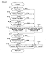
- step S12 of the process of FIG. 2 may be replaced with step S12a as shown in FIG. 5 .
- step S12a it is determined whether or not the downstream side catalyst temperature TATC is higher than the predetermined downstream side catalyst temperature TATCX. If the answer to step S12a is affirmative (YES), the process proceeds to step S16. If the answer to step S12a is negative (NO), the process proceeds to step S13.
- step S12 of the process of FIG. 4 in the second embodiment may be similarly replaced with step S12a.
- steps S12 and S14 may be deleted, and the first switching valve 13 may be switched to the bypass passage closed state when the engine coolant temperature TW is equal to or less than the predetermined temperature TWX.
- steps S11 and S14 may be deleted, and the first switching valve 13 may be switched to the bypass passage closed state when the upstream side catalyst temperature TPTC is equal to or less than the predetermined upstream side catalyst temperature TPTCX.
- the present invention can be applied also to a gasoline internal combustion engine and a control system therefor, in addition to the above-described diesel internal combustion engine. Further, the present invention can be applied also to a watercraft propulsion engine such as an outboard engine having a vertically extending crankshaft and to a control for such engine.
Landscapes
- Engineering & Computer Science (AREA)
- Chemical & Material Sciences (AREA)
- Combustion & Propulsion (AREA)
- Mechanical Engineering (AREA)
- General Engineering & Computer Science (AREA)
- Chemical Kinetics & Catalysis (AREA)
- Health & Medical Sciences (AREA)
- Toxicology (AREA)
- Exhaust Gas After Treatment (AREA)
- Exhaust Gas Treatment By Means Of Catalyst (AREA)
- Supercharger (AREA)
Claims (13)
- Verbrennungsmotor, welcher aufweist: einen Turbolader (9), wobei der Verbrennungsmotor (1) eine Turbine (9a) des Turboladers (9) umfasst, die in einem Abgassystem (8) des Motors angeordnet ist, einen Katalysator (11) an einer stromaufwertigen Seite, welcher stromaufwärts der Turbine (9a) angeordnet ist, einen Katalysatorumgehungsdurchgang (12), welcher den Katalysator (11) an der stromaufwertigen Seite umgeht, ein Ein/Aus-Ventil (13) für den Katalysatorumgehungsdurchgang zum Öffnen und Schließen des Katalysatorumgehungsdurchgangs (12) und einen ersten Abgas-Rückführungsdurchgang (25, 25a; 25b) zum Rückführen eines Teils von Abgasen aus einem Bereich zwischen dem Katalysator (11) an der stromaufwertigen Seite und der Turbine (9a) zu einem Ansaugsystem (7) des Motors (1),
dadurch gekennzeichnet, dass das Ein/Aus-Ventil (13) für den Katalysatorumgehungsdurchgang an einem Verbindungsabschnitt angeordnet ist, welcher stromabwärts des Katalysators (11) an der stromaufwertigen Seite zwischen dem Katalysatorumgehungsdurchgang (12) und der Abgasleitung (8) gelegen ist,
wobei der erste Abgas-Rückführungsdurchgang (25, 25a; 25b) mit dem Abgassystem (8) stromabwärts des Ein/Aus-Ventils (13) des Katalysatorumgehungsdurchgangs verbunden ist. - Verbrennungsmotor nach Anspruch 1, ferner umfassend:einen zweiten Abgas-Rückführungsdurchgang (31, 25a) zum Rückführen eines Teils von Abgasen von einer stromaufwärtigen Seite des Katalysators (11) an der stromaufwertigen Seite zu dem Ansaugsystem (7) und ein Umschaltventil (32) zum Umschalten zwischen dem ersten AbgasRückführungsdurchgang (25a, 25b) und dem zweiten Abgas-Rück führungsdurchgang (31, 25a).
- Verbrennungsmotor nach Anspruch 1 oder 2, ferner umfassend einen Katalysator (33) an einer stromabwertigen Seite, welcher stromabwärts der Turbine (9a) angeordnet ist.
- Verbrennungsmotor nach Anspruch 3, ferner umfassend einen Turbinenumgehungsdurchgang (14), welcher die Turbine (9a) umgeht, und ein Ein/Aus-Ventil (15) für den Turbinenumgehungsdurchgang zum Öffnen und Schließen des Turbinenumgehungsdurchgangs (14), wobei der Katalysator (33) an der stromabwertigen Seite stromabwärts eines Abschnitts, an welchem der Abgasdurchgang (8) mit dem Turbinenumgehungsdurchgang (14) stromabwärts der Turbine (9a) verbunden ist, angeordnet ist.
- Verbrennungsmotor nach Anspruch 3 oder 4, ferner umfassend einen Partikelfilter (34), welcher stromabwärts des Katalysators (33) der stromabwertigen Seite angeordnet ist.
- Verbrennungsmotor nach Anspruch 5, ferner umfassend einen mageren Nox-Katalysator (35), welcher stromabwärts des Partikelfilters (34) angeordnet ist.
- Verbrennungsmotor nach einem der Ansprüche 3 bis 6, wobei der Katalysator (33) an der stromabwertigen Seite ein Drei-Wegekatalysator ist, welchem ein Nox-Bindemittel hinzugefügt wird, oder einen Oxidationskatalysator ist, welchem ein Kohlenwasserstoffadsorptionsmittel hinzugefügt ist.
- Verbrennungsmotor nach einem der Ansprüche 1 bis 7, wobei der Katalysator (11) an der stromaufwertigen Seite ein Katalysator ist aus einem Oxidationskatalysator, welchem ein Kohlenwasserstoffadsorptionsmittel hinzugefügt ist, einem Drei-Wegekatalysator, welchem ein Nox-Bindemittel hinzugefügt ist, und einem Drei-Wegekatalysator, welchem ein Nox-Bindemittel und ein Kohlenwasserstoffadsorptionsmittel hinzugefügt ist.
- Verbrennungsmotor nach einem der Ansprüche 7 oder 8, wobei das Nox-Bindemittel Cerium ist und wobei das Kohlenwasserstoffadsorptionsmittel Zeolith ist.
- Regelungs-/Steuerungssystem für einen Verbrennungsmotor, welcher einen Turbolader (9) aufweist, wobei der Verbrennungsmotor (1) eine Turbine (9a) des Turboladers (9), die in einem Abgassystem (8) des Motors angeordnet ist, einen Katalysator (11) an einer stromaufwertigen Seite, welcher stromaufwärts der Turbine (9a) angeordnet ist, einen Katalysatorumgehungsdurchgang (12), welcher den Katalysator (11) an der stromaufwertigen Seite umgeht, ein Ein/Aus-Ventil (13) für den Katalysatorumgehungsdurchgang zum Öffnen und Schließen des Katalysatorumgehungsdurchgangs (12), einen ersten Abgas-Rückführungsdurchgang (25a; 25b) zum Rückführen eines Teils von Abgasen aus einem Bereich zwischen dem Katalysator (11) an der stromaufwertigen Seite und der Turbine (9a) zu einem Ansaugsystem (7) des Motors, einen zweiten Abgas-Rückführungsdurchgang (31, 25a), zum Rückführen eines Teils von Abgasen von einer stromaufwärtigen Seite des Katalysators (11) an der stromaufwertigen Seite zu dem Ansaugsystem (7) und ein Umschaltventil (32) zum Umschalten zwischen dem ersten Abgas-Rückführungsdurchgang (25a, 25b) und dem zweiten Abgas-Rückführungsdurchgang (31, 25a) umfasst,
wobei das Ein/Aus-Ventil (13) des Katalysatorumgehungsdurchgangs an einem Verbindungsbereich angeordnet ist, welches stromabwärts des Katalysators (11) an der stromabwertigen Seite zwischen dem Katalysatorumgehungsdurchgang (12) und der Abgasleitung (8) gelegen ist,
wobei der erste Abgas-Rückführungsdurchgang (25, 25a; 25b) mit dem Abgassystem (8) stromaufwärts des Ein/Aus-Ventils (13) des Katalysatorumgehungsdurchgangs verbunden ist,
wobei das Regelungs-/Steuerungssystem angepasst ist, um das Ein/Aus-Ventil (13) des Katalysatorumgehungsdurchgangs zu schließen und das Umschaltventil (32) in einen Zustand umzuschalten, in welchem der erste Abgas-Rückführungsdurchgang (25a, 25b) verbunden ist, wenn eine Temperatur (TW) des Motors niedrig ist, wobei, wenn eine Temperatur (TEGR) von Abgasen, die durch den ersten Abgas-Rückführungsdurchgang (25a, 25b) rückgeführt werden, eine vorbestimmte Abgastemperatur (TEGRX) übersteigt, schaltet das Reglungs-/Steuerungssystem das Umschaltventil (32) in den anderen Zustand des Verbindens des zweiten Abgas-Rückführungsdurchgangs (31, 25a). - Regelungs-/Steuerungssystem nach Anspruch 10, wobei das Regelungs-/Steuerungssystem angepasst ist, das Ein/Aus-Ventil (13) des Katalysatorumgehungsdurchgangs zu schließen, wenn eine Temperatur (TW) des Motors niedrig ist.
- Regelungs-/Steuerungssystem nach Anspruch 10, wobei das Regelungs-/Steuerungssystem angepasst ist das Ein/Aus-Ventil (13) des Katalysatorumgehungsdurchgangs zu schließen, wenn eine Temperatur (TPTC) des Katalysators (11) an der stromaufwertigen Seite gleich einer oder kleiner als eine vorbestimmte Katalysatortemperatur (TPTCX) ist.
- Regelungs-/Steuerungssystem nach Anspruch 10, wobei das Regelungs-/Steuerungssystem (13) angepasst ist, das Ein/Aus-Ventil des Katalysatorumgehungsdurchgangs zu öffnen, wenn der Motor bremst (AP = 0, NE > NEIDL).
Applications Claiming Priority (3)
| Application Number | Priority Date | Filing Date | Title |
|---|---|---|---|
| JP2007052696 | 2007-03-02 | ||
| JP2007214417A JP5037263B2 (ja) | 2007-03-02 | 2007-08-21 | 内燃機関の制御装置 |
| PCT/JP2008/052280 WO2008108141A1 (ja) | 2007-03-02 | 2008-02-13 | 内燃機関及び内燃機関の制御装置 |
Publications (3)
| Publication Number | Publication Date |
|---|---|
| EP2116703A4 EP2116703A4 (de) | 2009-11-11 |
| EP2116703A1 EP2116703A1 (de) | 2009-11-11 |
| EP2116703B1 true EP2116703B1 (de) | 2013-02-13 |
Family
ID=39738038
Family Applications (1)
| Application Number | Title | Priority Date | Filing Date |
|---|---|---|---|
| EP08711138A Not-in-force EP2116703B1 (de) | 2007-03-02 | 2008-02-13 | Verbrennungsmotor und steuervorrichtung für einen verbrennungsmotor |
Country Status (4)
| Country | Link |
|---|---|
| US (1) | US8205449B2 (de) |
| EP (1) | EP2116703B1 (de) |
| JP (1) | JP5037263B2 (de) |
| WO (1) | WO2008108141A1 (de) |
Families Citing this family (25)
| Publication number | Priority date | Publication date | Assignee | Title |
|---|---|---|---|---|
| DE102008038720A1 (de) * | 2008-08-12 | 2010-02-18 | Man Nutzfahrzeuge Ag | Verfahren und Vorrichtung zur Regeneration eines im Abgasstrang einer Brennkraftmaschine angeordneten Partikelfilters |
| DE102008043487A1 (de) * | 2008-11-05 | 2010-05-20 | Robert Bosch Gmbh | Brennkraftmaschine mit Turbolader und Oxidationskatalysator |
| DE102008057572B4 (de) * | 2008-11-15 | 2021-09-02 | Bayerische Motoren Werke Aktiengesellschaft | Abgasanlage für eine Brennkraftmaschine |
| US10145283B2 (en) | 2009-03-05 | 2018-12-04 | Volvo Lastvagnar Ab | Diesel engine system and method and apparatus for handling diesel engine exhaust |
| GB2472228B (en) * | 2009-07-29 | 2016-01-27 | Ford Global Tech Llc | A method for reducing the fuel consumption of an engine |
| US8490383B2 (en) * | 2009-09-14 | 2013-07-23 | Fev Gmbh | Exhaust system for internal combustion engine |
| US8978360B2 (en) * | 2009-09-15 | 2015-03-17 | Ford Global Technologies, Llc | Hydrocarbon and NOx trap |
| US8096125B2 (en) | 2009-12-23 | 2012-01-17 | Ford Global Technologies, Llc | Methods and systems for emission system control |
| US8443602B2 (en) * | 2010-03-30 | 2013-05-21 | GM Global Technology Operations LLC | Closely-coupled exhaust aftertreatment device for a turbocharged internal combustion engine |
| US8042527B2 (en) * | 2010-08-05 | 2011-10-25 | Ford Global Technologies, Llc | Coordination of HP and LP EGR |
| JP5246350B2 (ja) * | 2010-09-29 | 2013-07-24 | トヨタ自動車株式会社 | ターボ過給機付き内燃機関 |
| CN103140659A (zh) * | 2010-10-13 | 2013-06-05 | 丰田自动车株式会社 | 内燃机的控制装置 |
| US8607566B2 (en) * | 2011-04-15 | 2013-12-17 | GM Global Technology Operations LLC | Internal combustion engine with emission treatment interposed between two expansion phases |
| US20130000297A1 (en) * | 2011-06-29 | 2013-01-03 | Electro-Motive Diesel, Inc. | Emissions reduction system |
| KR101875228B1 (ko) * | 2012-01-27 | 2018-07-05 | 두산인프라코어 주식회사 | Urea-scr 시스템 장치 및 제어방법 |
| GB2519164A (en) * | 2013-10-14 | 2015-04-15 | Gm Global Tech Operations Inc | Method of controlling the pressure of a turbocharger |
| DK2987978T3 (da) * | 2014-08-21 | 2019-05-06 | Winterthur Gas & Diesel Ag | Drivenhed og fremgangsmåde til drift af en drivenhed |
| US10480460B2 (en) | 2014-12-17 | 2019-11-19 | Tenneco Gmbh | EGR system with particle filter for a gasoline engine |
| DE102014118813B4 (de) * | 2014-12-17 | 2025-06-26 | Tenneco Gmbh | AGR-System mit Partikelfilter für Ottomotor |
| JP6337872B2 (ja) * | 2015-11-24 | 2018-06-06 | トヨタ自動車株式会社 | 内燃機関の制御装置 |
| JP6330836B2 (ja) * | 2016-03-11 | 2018-05-30 | マツダ株式会社 | エンジンの排気装置 |
| DE102016119211A1 (de) * | 2016-10-10 | 2018-04-12 | Volkswagen Aktiengesellschaft | Vorrichtung und Verfahren zur Abgasnachbehandlung eines Verbrennungsmotors |
| JP2018062897A (ja) * | 2016-10-13 | 2018-04-19 | 川崎重工業株式会社 | ガスエンジンシステム |
| WO2020260041A1 (de) * | 2019-06-27 | 2020-12-30 | Tenneco Gmbh | Abgasnachbehandlungssystem für einen verbrennungsmotor |
| US10920695B1 (en) * | 2019-09-05 | 2021-02-16 | Ford Global Technologies, Llc | Methods and systems for regeneration of an exhaust aftertreatment device |
Family Cites Families (17)
| Publication number | Priority date | Publication date | Assignee | Title |
|---|---|---|---|---|
| JP2675405B2 (ja) * | 1989-08-12 | 1997-11-12 | マツダ株式会社 | エンジンの排気ガス浄化装置 |
| JPH09209742A (ja) * | 1996-02-05 | 1997-08-12 | Toyota Motor Corp | 過給機付き内燃機関の排気制御装置 |
| JPH11229973A (ja) * | 1998-02-17 | 1999-08-24 | Isuzu Motors Ltd | エンジンのegr装置 |
| GB0021118D0 (en) * | 2000-08-29 | 2000-10-11 | Johnson Matthey Plc | Exhaust system for lean-burn engines |
| GB0100067D0 (en) * | 2001-01-03 | 2001-02-14 | Johnson Matthey Plc | Diesel exhaust system including NOx trap |
| JP2002276346A (ja) * | 2001-03-23 | 2002-09-25 | Hitachi Ltd | ターボ過給機付き火花点火筒内噴射エンジンとその制御法 |
| JP2002349241A (ja) * | 2001-05-24 | 2002-12-04 | Isuzu Motors Ltd | ディーゼルエンジンの排気浄化装置 |
| JP3876705B2 (ja) * | 2001-12-13 | 2007-02-07 | いすゞ自動車株式会社 | ディーゼルエンジンの排気ガス浄化システム |
| JP2004019624A (ja) * | 2002-06-20 | 2004-01-22 | Toyota Motor Corp | 内燃機関の排気浄化装置 |
| US6946013B2 (en) * | 2002-10-28 | 2005-09-20 | Geo2 Technologies, Inc. | Ceramic exhaust filter |
| US6675579B1 (en) * | 2003-02-06 | 2004-01-13 | Ford Global Technologies, Llc | HCCI engine intake/exhaust systems for fast inlet temperature and pressure control with intake pressure boosting |
| JP2005171932A (ja) | 2003-12-12 | 2005-06-30 | Toyota Motor Corp | 内燃機関の排気浄化装置 |
| US7168237B2 (en) * | 2004-02-27 | 2007-01-30 | Nissan Motor Co., Ltd. | Deterioration diagnosing device and diagnosing method for exhaust gas purification catalyst |
| GB2416565B (en) * | 2004-07-23 | 2008-02-13 | Visteon Global Tech Inc | Pressure boosted IC engine with exhaust gas recirculation |
| JP2006046288A (ja) * | 2004-08-09 | 2006-02-16 | Hino Motors Ltd | 排気浄化装置 |
| JP2006220046A (ja) * | 2005-02-09 | 2006-08-24 | Toyota Motor Corp | ディーゼルハイブリッド車両の排気浄化装置 |
| US7332454B2 (en) * | 2005-03-16 | 2008-02-19 | Sud-Chemie Inc. | Oxidation catalyst on a substrate utilized for the purification of exhaust gases |
-
2007
- 2007-08-21 JP JP2007214417A patent/JP5037263B2/ja not_active Expired - Fee Related
-
2008
- 2008-02-13 EP EP08711138A patent/EP2116703B1/de not_active Not-in-force
- 2008-02-13 WO PCT/JP2008/052280 patent/WO2008108141A1/ja not_active Ceased
- 2008-02-13 US US12/301,663 patent/US8205449B2/en not_active Expired - Fee Related
Also Published As
| Publication number | Publication date |
|---|---|
| JP5037263B2 (ja) | 2012-09-26 |
| US20100064686A1 (en) | 2010-03-18 |
| US8205449B2 (en) | 2012-06-26 |
| WO2008108141A1 (ja) | 2008-09-12 |
| JP2008248878A (ja) | 2008-10-16 |
| EP2116703A4 (de) | 2009-11-11 |
| EP2116703A1 (de) | 2009-11-11 |
Similar Documents
| Publication | Publication Date | Title |
|---|---|---|
| US8205449B2 (en) | Internal combustion engine and control system for internal combustion engine | |
| US6962045B2 (en) | Exhaust gas apparatus and method for purifying exhaust gas in internal combustion engine | |
| US8371108B2 (en) | Twin turbo diesel aftertreatment system | |
| US6742329B2 (en) | Exhaust emission control system of diesel engine | |
| US7758833B2 (en) | Exhaust gas purifying apparatus for internal combustion engine | |
| US20110120123A1 (en) | Low pressure turbine waste gate for diesel engine having two stage turbocharger | |
| US7340884B2 (en) | Exhaust purifying apparatus and exhaust purifying method for internal combustion engine | |
| US7827783B2 (en) | Exhaust gas purifying apparatus for internal combustion engine | |
| JP2004251230A (ja) | エンジン用酸化触媒の活性判定装置、及び、エンジンの排気浄化装置 | |
| JP4857220B2 (ja) | 内燃機関の排気浄化装置 | |
| US20180266344A1 (en) | Internal combustion engine | |
| JP2008002351A (ja) | 内燃機関の排気還流装置 | |
| JP2004150416A (ja) | パティキュレートフィルタの再生方法 | |
| JP2006200473A (ja) | 排ガス後処理装置付きエンジンの制御装置 | |
| JPH1068315A (ja) | 内燃機関の排気浄化装置 | |
| US10731583B2 (en) | System and method of controlling oxygen purge of three-way catalyst | |
| JP2008138638A (ja) | 内燃機関の排気還流装置 | |
| JPH09209742A (ja) | 過給機付き内燃機関の排気制御装置 | |
| JP5131477B2 (ja) | エンジンの排気浄化装置 | |
| JP4893493B2 (ja) | 内燃機関の排気浄化装置 | |
| US10781737B1 (en) | Regeneration of automotive exhaust aftertreatment device using diverted boost air during deceleration | |
| JP2010007634A (ja) | 内燃機関の排気浄化装置 | |
| JP3641964B2 (ja) | 内燃機関の排気浄化装置 | |
| JP4148072B2 (ja) | 内燃機関の触媒制御方法及び触媒制御装置 | |
| JP5379733B2 (ja) | エンジンの排気浄化装置 |
Legal Events
| Date | Code | Title | Description |
|---|---|---|---|
| PUAI | Public reference made under article 153(3) epc to a published international application that has entered the european phase |
Free format text: ORIGINAL CODE: 0009012 |
|
| 17P | Request for examination filed |
Effective date: 20081111 |
|
| A4 | Supplementary search report drawn up and despatched |
Effective date: 20090327 |
|
| AK | Designated contracting states |
Kind code of ref document: A1 Designated state(s): AT BE BG CH CY CZ DE DK EE ES FI FR GB GR HR HU IE IS IT LI LT LU LV MC MT NL NO PL PT RO SE SI SK TR |
|
| 17Q | First examination report despatched |
Effective date: 20091029 |
|
| DAX | Request for extension of the european patent (deleted) | ||
| GRAP | Despatch of communication of intention to grant a patent |
Free format text: ORIGINAL CODE: EPIDOSNIGR1 |
|
| GRAS | Grant fee paid |
Free format text: ORIGINAL CODE: EPIDOSNIGR3 |
|
| GRAA | (expected) grant |
Free format text: ORIGINAL CODE: 0009210 |
|
| AK | Designated contracting states |
Kind code of ref document: B1 Designated state(s): DE GB |
|
| RBV | Designated contracting states (corrected) |
Designated state(s): DE GB |
|
| REG | Reference to a national code |
Ref country code: GB Ref legal event code: FG4D |
|
| REG | Reference to a national code |
Ref country code: DE Ref legal event code: R096 Ref document number: 602008022092 Country of ref document: DE Effective date: 20130411 |
|
| PGFP | Annual fee paid to national office [announced via postgrant information from national office to epo] |
Ref country code: DE Payment date: 20130228 Year of fee payment: 6 |
|
| PLBE | No opposition filed within time limit |
Free format text: ORIGINAL CODE: 0009261 |
|
| STAA | Information on the status of an ep patent application or granted ep patent |
Free format text: STATUS: NO OPPOSITION FILED WITHIN TIME LIMIT |
|
| 26N | No opposition filed |
Effective date: 20131114 |
|
| GBPC | Gb: european patent ceased through non-payment of renewal fee |
Effective date: 20130513 |
|
| REG | Reference to a national code |
Ref country code: DE Ref legal event code: R097 Ref document number: 602008022092 Country of ref document: DE Effective date: 20131114 |
|
| PG25 | Lapsed in a contracting state [announced via postgrant information from national office to epo] |
Ref country code: GB Free format text: LAPSE BECAUSE OF NON-PAYMENT OF DUE FEES Effective date: 20130513 |
|
| REG | Reference to a national code |
Ref country code: DE Ref legal event code: R119 Ref document number: 602008022092 Country of ref document: DE |
|
| REG | Reference to a national code |
Ref country code: DE Ref legal event code: R119 Ref document number: 602008022092 Country of ref document: DE Effective date: 20140902 |
|
| PG25 | Lapsed in a contracting state [announced via postgrant information from national office to epo] |
Ref country code: DE Free format text: LAPSE BECAUSE OF NON-PAYMENT OF DUE FEES Effective date: 20140902 |