EP2116736A2 - Procédé de commande d'un embrayage à friction automatisé - Google Patents
Procédé de commande d'un embrayage à friction automatisé Download PDFInfo
- Publication number
- EP2116736A2 EP2116736A2 EP09155821A EP09155821A EP2116736A2 EP 2116736 A2 EP2116736 A2 EP 2116736A2 EP 09155821 A EP09155821 A EP 09155821A EP 09155821 A EP09155821 A EP 09155821A EP 2116736 A2 EP2116736 A2 EP 2116736A2
- Authority
- EP
- European Patent Office
- Prior art keywords
- clutch
- ausrückweges
- disengagement
- speed
- soll
- Prior art date
- Legal status (The legal status is an assumption and is not a legal conclusion. Google has not performed a legal analysis and makes no representation as to the accuracy of the status listed.)
- Withdrawn
Links
- 238000000034 method Methods 0.000 title claims abstract description 44
- 238000012937 correction Methods 0.000 claims description 20
- 230000006978 adaptation Effects 0.000 claims description 10
- 230000007704 transition Effects 0.000 claims description 6
- 230000004913 activation Effects 0.000 claims description 5
- 230000005540 biological transmission Effects 0.000 claims description 5
- 230000008569 process Effects 0.000 abstract description 8
- 238000010586 diagram Methods 0.000 description 7
- 230000001419 dependent effect Effects 0.000 description 5
- 238000004519 manufacturing process Methods 0.000 description 5
- 230000000875 corresponding effect Effects 0.000 description 4
- 230000006870 function Effects 0.000 description 3
- 230000001133 acceleration Effects 0.000 description 2
- 230000001276 controlling effect Effects 0.000 description 2
- 238000006073 displacement reaction Methods 0.000 description 2
- 230000000750 progressive effect Effects 0.000 description 2
- 230000009467 reduction Effects 0.000 description 2
- 230000036962 time dependent Effects 0.000 description 2
- 238000000418 atomic force spectrum Methods 0.000 description 1
- 230000015572 biosynthetic process Effects 0.000 description 1
- 238000006243 chemical reaction Methods 0.000 description 1
- 238000010276 construction Methods 0.000 description 1
- 230000002596 correlated effect Effects 0.000 description 1
- 230000008878 coupling Effects 0.000 description 1
- 238000010168 coupling process Methods 0.000 description 1
- 238000005859 coupling reaction Methods 0.000 description 1
- 230000007423 decrease Effects 0.000 description 1
- 230000000994 depressogenic effect Effects 0.000 description 1
- 238000013461 design Methods 0.000 description 1
- 238000011161 development Methods 0.000 description 1
- 230000018109 developmental process Effects 0.000 description 1
- 238000011156 evaluation Methods 0.000 description 1
- 238000002347 injection Methods 0.000 description 1
- 239000007924 injection Substances 0.000 description 1
- 238000013507 mapping Methods 0.000 description 1
- 230000001105 regulatory effect Effects 0.000 description 1
- 230000001953 sensory effect Effects 0.000 description 1
- 239000000725 suspension Substances 0.000 description 1
- 210000002105 tongue Anatomy 0.000 description 1
- 238000012549 training Methods 0.000 description 1
Images


Classifications
-
- F—MECHANICAL ENGINEERING; LIGHTING; HEATING; WEAPONS; BLASTING
- F16—ENGINEERING ELEMENTS AND UNITS; GENERAL MEASURES FOR PRODUCING AND MAINTAINING EFFECTIVE FUNCTIONING OF MACHINES OR INSTALLATIONS; THERMAL INSULATION IN GENERAL
- F16D—COUPLINGS FOR TRANSMITTING ROTATION; CLUTCHES; BRAKES
- F16D48/00—External control of clutches
- F16D48/06—Control by electric or electronic means, e.g. of fluid pressure
-
- F—MECHANICAL ENGINEERING; LIGHTING; HEATING; WEAPONS; BLASTING
- F16—ENGINEERING ELEMENTS AND UNITS; GENERAL MEASURES FOR PRODUCING AND MAINTAINING EFFECTIVE FUNCTIONING OF MACHINES OR INSTALLATIONS; THERMAL INSULATION IN GENERAL
- F16D—COUPLINGS FOR TRANSMITTING ROTATION; CLUTCHES; BRAKES
- F16D2500/00—External control of clutches by electric or electronic means
- F16D2500/30—Signal inputs
- F16D2500/302—Signal inputs from the actuator
- F16D2500/3023—Force
-
- F—MECHANICAL ENGINEERING; LIGHTING; HEATING; WEAPONS; BLASTING
- F16—ENGINEERING ELEMENTS AND UNITS; GENERAL MEASURES FOR PRODUCING AND MAINTAINING EFFECTIVE FUNCTIONING OF MACHINES OR INSTALLATIONS; THERMAL INSULATION IN GENERAL
- F16D—COUPLINGS FOR TRANSMITTING ROTATION; CLUTCHES; BRAKES
- F16D2500/00—External control of clutches by electric or electronic means
- F16D2500/30—Signal inputs
- F16D2500/302—Signal inputs from the actuator
- F16D2500/3026—Stroke
-
- F—MECHANICAL ENGINEERING; LIGHTING; HEATING; WEAPONS; BLASTING
- F16—ENGINEERING ELEMENTS AND UNITS; GENERAL MEASURES FOR PRODUCING AND MAINTAINING EFFECTIVE FUNCTIONING OF MACHINES OR INSTALLATIONS; THERMAL INSULATION IN GENERAL
- F16D—COUPLINGS FOR TRANSMITTING ROTATION; CLUTCHES; BRAKES
- F16D2500/00—External control of clutches by electric or electronic means
- F16D2500/50—Problem to be solved by the control system
- F16D2500/502—Relating the clutch
- F16D2500/50245—Calibration or recalibration of the clutch touch-point
- F16D2500/50248—During assembly
-
- F—MECHANICAL ENGINEERING; LIGHTING; HEATING; WEAPONS; BLASTING
- F16—ENGINEERING ELEMENTS AND UNITS; GENERAL MEASURES FOR PRODUCING AND MAINTAINING EFFECTIVE FUNCTIONING OF MACHINES OR INSTALLATIONS; THERMAL INSULATION IN GENERAL
- F16D—COUPLINGS FOR TRANSMITTING ROTATION; CLUTCHES; BRAKES
- F16D2500/00—External control of clutches by electric or electronic means
- F16D2500/50—Problem to be solved by the control system
- F16D2500/502—Relating the clutch
- F16D2500/50245—Calibration or recalibration of the clutch touch-point
- F16D2500/50251—During operation
-
- F—MECHANICAL ENGINEERING; LIGHTING; HEATING; WEAPONS; BLASTING
- F16—ENGINEERING ELEMENTS AND UNITS; GENERAL MEASURES FOR PRODUCING AND MAINTAINING EFFECTIVE FUNCTIONING OF MACHINES OR INSTALLATIONS; THERMAL INSULATION IN GENERAL
- F16D—COUPLINGS FOR TRANSMITTING ROTATION; CLUTCHES; BRAKES
- F16D2500/00—External control of clutches by electric or electronic means
- F16D2500/70—Details about the implementation of the control system
- F16D2500/704—Output parameters from the control unit; Target parameters to be controlled
- F16D2500/70402—Actuator parameters
- F16D2500/7041—Position
- F16D2500/70412—Clutch position change rate
-
- F—MECHANICAL ENGINEERING; LIGHTING; HEATING; WEAPONS; BLASTING
- F16—ENGINEERING ELEMENTS AND UNITS; GENERAL MEASURES FOR PRODUCING AND MAINTAINING EFFECTIVE FUNCTIONING OF MACHINES OR INSTALLATIONS; THERMAL INSULATION IN GENERAL
- F16D—COUPLINGS FOR TRANSMITTING ROTATION; CLUTCHES; BRAKES
- F16D2500/00—External control of clutches by electric or electronic means
- F16D2500/70—Details about the implementation of the control system
- F16D2500/706—Strategy of control
- F16D2500/70605—Adaptive correction; Modifying control system parameters, e.g. gains, constants, look-up tables
Definitions
- the invention relates to a method for controlling an automated friction clutch, which is designed as a diaphragm spring clutch and is arranged as starting and shifting clutch in a drive train of a motor vehicle between a drive motor and a gearbox, wherein during a clutch actuation at least one operating parameter of the friction clutch is detected by sensors, and at least one adaptation parameter for the correction of a control parameter of the assigned clutch actuator is derived from the course of the operating parameter.
- Diaphragm spring clutches have long been known and have prevailed because of their robust and space-saving design, especially in motor vehicles as a preferred type passively closable dry clutches.
- the pressure spring is formed as a diaphragm spring, by means of a pressure plate axially against a rotatably connected to the drive shaft of the drive motor and usually formed as a flywheel counter pressure plate is pressed, whereby at least one provided with friction linings and rotatably connected to the input shaft of the gearbox clutched drive disc is, and thus frictionally a torque can be transmitted from the drive motor to the manual transmission.
- the diaphragm spring is usually designed so that it ensures a safe torque transmission over the entire life.
- the diaphragm spring inner spring tongues on which a trained as Monausscher clutch actuator or via an externally arranged clutch plate pivoting release lever via a release bearing can initiate an axial disengaging force.
- the support of the diaphragm spring can be distinguished between a pulled clutch, in which the release force acts in the direction of the gearbox, and a depressed clutch, in which the release force acts in the direction of the drive motor.
- the working range ie, the range between the to-way point x K0 for the fully engaged state and the up-way point x K1 for the fully disengaged state shifts from right to left in the course of wear of the friction linings ; in the presentation of Fig. 4 ie from the range x K0 to x K1 to the range x K0 'to x K1 '.
- the corresponding courses of the release force on the Ausgurweg at a disengagement are in Fig. 4 in simplified form in each case as dash-dotted curve F KA and F KA 'shown below the curve for the release force F K_Ausr .
- FIG Fig. 5 A more detailed representation of a typical course of the release force F KA over the release travel x K during a disengagement process of a diaphragm spring clutch is shown in FIG Fig. 5 qualitatively reproduced.
- the course of Ausgurkraft F KA is divided into an initial rise area A with a largely linear increase in Ausschreibkraft F KA on Ausschreibweg x K , an adjoining transition region B with a degressive transition of Ausschreibkraft F KA to a value in a subsequent Saturation region C remains largely constant and there is in the range of achievable in normal operation maximum release force F KA_max .
- the release force F KA initially decreases with increasing release travel x K , in order subsequently to increase again.
- a possible method for adapting the controller characteristic curve ie for adapting the controller characteristic curve to the respectively current disengaging force curve F KA (x K ) of the diaphragm spring clutch, is the DE 10 2005 039 922 A1 but not to be seen.
- the reference point of a friction clutch also referred to as the contact point, is determined or adapted in which the respective friction elements just come into contact or separate and the friction clutch is thus an infinitesimal one can transmit small torque.
- Such methods are based on sensory detectable reactions of operating parameters associated with or adjacent components, such as the travel of the clutch actuator, the speed of the transmission input shaft or the drive motor, or the injection quantity of the drive motor.
- the present invention has the object to provide a method with which additional information about the course of Ausgurkraft F KA (x K ) determined and can be used to improve the control of an associated clutch actuator with little effort.
- the invention is therefore based on a method for controlling an automated friction clutch, which is designed as a diaphragm spring clutch and arranged as a starting and shifting clutch in a drive train of a motor vehicle between a drive motor and a transmission, wherein during a clutch actuation at least one operating parameter the friction clutch is detected by sensors, and from the course of the operating parameter at least one adaptation parameter for correcting a control parameter of the associated clutch actuator is derived.
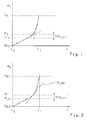
- the friction clutch is completely disengaged with constant control or actuation of the clutch actuator, that during the disengagement of Ausenburgweg is detected as a function of Auslessnesszeit, and that determines at least one characteristic characteristic from the time course of Ausenburgweges is determined from the at least one adaptation parameter for correcting a control parameter of the clutch actuator.
- the invention is based on the finding that in a disengagement of a diaphragm spring clutch with constant control or actuation of the clutch actuator, ie at a constant increase in force, a typical time course of Ausgurweges x K (t) results, directly with the Ausschreibkraftkennline, ie the Course of the release force F KA (x K ), correlated. Due to the constant force gradient of the clutch actuator, the result of the linear increase of the spring-side disengagement force F KA (x K ) (see region A in FIG Fig. 5 ) In the time course of Ausschreibweges x K (t) initially a relatively small linear increase of Ausschreibweges x K (t).
- This relationship is used in the present method to determine at least one characteristic characteristic value from the time profile of the disengaging path x K (t) detected during a constantly controlled disengaging operation, from which at least one adaptation parameter for correcting a control parameter of the clutch actuator is determined.
- This adaptation parameter is thus implicitly also dependent on the travel path of the disengagement force F KA (x K ), which is determined by the current state of the diaphragm spring clutch, in particular by a production-related production spread and the wear state of the friction linings.
- the constant control or actuation of the clutch actuator is generated in its formation as a pressure-actuated actuating cylinder by a constant throttle cross-section of an associated proportional valve or by a constant frequency of an associated frequency-modulated clock valve, and in its electromechanical training by a constant current or voltage gradient of the associated electric motor.
- the inventive method requires only the presence of a travel sensor and a timer, which are anyway present in an automated clutch control. An additional sensor is therefore not required for the application of the method. The procedure can thus be integrated into each control device of an automated diaphragm spring clutch without great effort.
- the correction of the end point x LE can take place in a manner known per se such that the hitherto valid end point x LE_alt is replaced by the new end point x LE_new or changed in the direction of the new end point x LE_new .
- the knowledge of the end point x LE of the linear rise range at the beginning of Ausgurweges x K (t) can be used in a complete or partial disengagement of the diaphragm spring clutch to control the clutch actuator to reach the end point x LE with constant control time-dependent, and another Move away from the endpoint x LE controlled path-dependent. This results in each case a simplification and acceleration of the control of the disengagement.
- the characteristic Ausgurwegtician x S can be determined at the end or after the disengagement as the intersection of a tangent to the linear rise range at the beginning of Ausschreibweges x K (t) and a tangent to the largely linear increase range at the end of Ausschreibweges x K (t).
- the data record can be determined empirically by the clutch or vehicle manufacturer and stored in a data memory of the clutch control unit.
- the inventive correction of a control parameter of the clutch actuator is performed for the first time after completion of the final assembly of the relevant motor vehicle at the vehicle manufacturer.
- the correction according to the invention of a control parameter of the clutch actuator is preferably carried out at each restart of the motor vehicle.
- a Ausschwegtician x S characteristic of the end point x LE of the linear region as the intersection of a tangent to the linear rise region at the beginning of Ausschreibweges x K (t) and a tangent to the largely linear rise region at the end of Ausschreibweges x K (t ) is determined.
- the clutch-specific correction value ⁇ x Korr can be determined from the determined waypoint x S, for example, by means of a previously empirically determined by the clutch or vehicle manufacturer and stored in a data memory of the clutch control unit record.
- the linear point end point x LE determined in this way can be used as a new valid end point or to correct a hitherto valid end point of the lower linear rise of the curve x K (t) of the release path over time.
- control parameter determined in this way can also be used in normal operation as the basic gain factor of the clutch controller.
- the disengagement speed v K_b of the upper disengagement process denoted by a dash-dotted tangent is greater than the reference speed v K_soll , that is to say v K_b > v K_soll , so that a reduction of the relevant control parameter of the control unit is achieved in order to achieve the desired speed v K_soll Clutch actuator is required.
Landscapes
- Engineering & Computer Science (AREA)
- General Engineering & Computer Science (AREA)
- Physics & Mathematics (AREA)
- Fluid Mechanics (AREA)
- Mechanical Engineering (AREA)
- Hydraulic Clutches, Magnetic Clutches, Fluid Clutches, And Fluid Joints (AREA)
Applications Claiming Priority (1)
| Application Number | Priority Date | Filing Date | Title |
|---|---|---|---|
| DE102008001682A DE102008001682A1 (de) | 2008-05-09 | 2008-05-09 | Verfahren zur Steuerung einer automatisierten Reibungskupplung |
Publications (2)
| Publication Number | Publication Date |
|---|---|
| EP2116736A2 true EP2116736A2 (fr) | 2009-11-11 |
| EP2116736A3 EP2116736A3 (fr) | 2012-06-27 |
Family
ID=40510598
Family Applications (1)
| Application Number | Title | Priority Date | Filing Date |
|---|---|---|---|
| EP09155821A Withdrawn EP2116736A3 (fr) | 2008-05-09 | 2009-03-23 | Procédé de commande d'un embrayage à friction automatisé |
Country Status (3)
| Country | Link |
|---|---|
| US (1) | US8090513B2 (fr) |
| EP (1) | EP2116736A3 (fr) |
| DE (1) | DE102008001682A1 (fr) |
Cited By (1)
| Publication number | Priority date | Publication date | Assignee | Title |
|---|---|---|---|---|
| WO2010118724A1 (fr) * | 2009-04-17 | 2010-10-21 | Schaeffler Technologies Gmbh & Co. Kg | Paramètre d'embrayage |
Families Citing this family (5)
| Publication number | Priority date | Publication date | Assignee | Title |
|---|---|---|---|---|
| DE102010017867A1 (de) * | 2009-05-05 | 2010-11-18 | Luk Lamellen Und Kupplungsbau Beteiligungs Kg | Sichere Tastpunktermittlung |
| GB2481838B (en) * | 2010-07-08 | 2017-05-31 | Gm Global Tech Operations Llc | Hydraulic clutch and method for determining an adaptive clutch fill volume of the hydraulic clutch |
| DE102010039172B4 (de) * | 2010-08-11 | 2023-12-07 | Zf Friedrichshafen Ag | Verfahren zur Ermittlung eines Anlegebetätigungsdruckwertes eines reibschlüssigen Schaltelements |
| DE102011101870B4 (de) * | 2011-05-16 | 2017-08-10 | Iav Gmbh Ingenieurgesellschaft Auto Und Verkehr | Verfahren zur Schätzung von Kupplungsparametern |
| DE102012005765A1 (de) * | 2012-03-23 | 2013-09-26 | Deere & Company | Verfahren zur Füllmengenbestimmung |
Citations (2)
| Publication number | Priority date | Publication date | Assignee | Title |
|---|---|---|---|---|
| DE10163438A1 (de) | 2001-12-21 | 2003-07-03 | Zahnradfabrik Friedrichshafen | Verfahren zur Ermittlung des Kupplungsanlegepunktes |
| DE102005039922A1 (de) | 2005-08-24 | 2007-03-08 | Zf Friedrichshafen Ag | Einrichtung zum Betätigen einer Membranfederkupplung für Fahrzeuge |
Family Cites Families (9)
| Publication number | Priority date | Publication date | Assignee | Title |
|---|---|---|---|---|
| DE19953032A1 (de) * | 1998-11-09 | 2000-05-11 | Luk Getriebe Systeme Gmbh | Kraftfahrzeug |
| AU2003218941A1 (en) * | 2002-03-07 | 2003-09-16 | Luk Lamellen Und Kupplungsbau Beteilgungs Kg | Control system and method for the position adjustment of a transmission of motion |
| DE102006019824A1 (de) * | 2006-04-28 | 2007-10-31 | Zf Friedrichshafen Ag | Verfahren zur Ermittlung einer Drehmomentkennlinie einer automatisierten Reibungskupplung |
| DE102007002343A1 (de) * | 2007-01-16 | 2008-07-17 | Zf Friedrichshafen Ag | Verfahren zur dynamischen Ermittlung eines Kupplungs-Ruhepunktes |
| DE102007015679A1 (de) * | 2007-03-31 | 2008-10-02 | Zf Friedrichshafen Ag | Verfahren zur Steuerung einer automatisierten Reibungskupplung |
| DE102009010136B4 (de) * | 2008-03-06 | 2018-11-08 | Schaeffler Technologies AG & Co. KG | Kupplungssystem mit einer Nachstelleinrichtung |
| DE102009014468A1 (de) * | 2008-04-07 | 2009-10-08 | Luk Lamellen Und Kupplungsbau Beteiligungs Kg | Verfahren zum Steuern einer Reibungskupplung |
| DE102008043492A1 (de) * | 2008-11-05 | 2010-05-06 | Zf Friedrichshafen Ag | Verfahren und Anordnung zum Bestimmen des Verschleißzustandes einer Schaltkupplung |
| DE102009053885B4 (de) * | 2009-11-20 | 2015-10-29 | Getrag Getriebe- Und Zahnradfabrik Hermann Hagenmeyer Gmbh & Cie Kg | Verfahren zur Kisspointadaption |
-
2008
- 2008-05-09 DE DE102008001682A patent/DE102008001682A1/de not_active Withdrawn
-
2009
- 2009-03-23 EP EP09155821A patent/EP2116736A3/fr not_active Withdrawn
- 2009-05-05 US US12/435,800 patent/US8090513B2/en not_active Expired - Fee Related
Patent Citations (2)
| Publication number | Priority date | Publication date | Assignee | Title |
|---|---|---|---|---|
| DE10163438A1 (de) | 2001-12-21 | 2003-07-03 | Zahnradfabrik Friedrichshafen | Verfahren zur Ermittlung des Kupplungsanlegepunktes |
| DE102005039922A1 (de) | 2005-08-24 | 2007-03-08 | Zf Friedrichshafen Ag | Einrichtung zum Betätigen einer Membranfederkupplung für Fahrzeuge |
Cited By (2)
| Publication number | Priority date | Publication date | Assignee | Title |
|---|---|---|---|---|
| WO2010118724A1 (fr) * | 2009-04-17 | 2010-10-21 | Schaeffler Technologies Gmbh & Co. Kg | Paramètre d'embrayage |
| US8892322B2 (en) | 2009-04-17 | 2014-11-18 | Schaeffler Technologies AG & Co. KG | Clutch parameters |
Also Published As
| Publication number | Publication date |
|---|---|
| US20090281700A1 (en) | 2009-11-12 |
| US8090513B2 (en) | 2012-01-03 |
| DE102008001682A1 (de) | 2009-11-12 |
| EP2116736A3 (fr) | 2012-06-27 |
Similar Documents
| Publication | Publication Date | Title |
|---|---|---|
| EP2129930B1 (fr) | Procede de commande d'un embrayage a friction automatise | |
| EP2013503B1 (fr) | Procédé pour déterminer une courbe caractéristique de couple de rotation d'un embrayage à friction automatique | |
| EP1898113B1 (fr) | chaîne cinématique de véhicule et procédé d'actionnement d'un actionneur à fluide agissant sur une transmission ou sur un dispositif d'embrayage | |
| DE102008026554A1 (de) | Verfahren zum Steuern einer Kupplungseinheit | |
| EP2116736A2 (fr) | Procédé de commande d'un embrayage à friction automatisé | |
| DE102007002343A1 (de) | Verfahren zur dynamischen Ermittlung eines Kupplungs-Ruhepunktes | |
| DE102008032476A1 (de) | Verfahren zum Steuern einer Kupplungseinheit | |
| DE102015121097A1 (de) | Elektronische Steuerung einer Handschaltgetriebekupplung | |
| EP2150718A1 (fr) | Procédé et dispositif de commande d'un embrayage | |
| DE102012103408A1 (de) | Verfahren zur Adaption einer Trennkupplung | |
| DE102014204343B4 (de) | Verfahren und Vorrichtung zur Steuerung einer automatisierten Reibungskupplung | |
| DE102014215753A1 (de) | Steuern eines Kupplungsaktuators | |
| DE102014210526B4 (de) | Verfahren sowie Steuergerät zur Steuerung einer Reibungskupplung | |
| DE102006014141A1 (de) | Verfahren zur Steuerung einer automatisierten Reibungskupplung | |
| DE10053110A1 (de) | Verfahren zum Betreiben einer Kupplung und Regeleinrichtung zur Durchführung des Verfahrens | |
| WO2022033796A1 (fr) | Procédé d'actionnement d'un élément de changement de rapport à mise en prise par friction | |
| DE102021207816B3 (de) | Verfahren zum Betätigen einer formschlüssigen Kupplung eines Getriebes sowie Kupplungsvorrichtung | |
| DE102016211735B4 (de) | Verfahren und Steuergerät zur Steuerung und/oder zur Regelung eines Antriebsstrangs eines Kraftfahrzeugs mit einem Antriebsmotor und mit mindestens einer Kupplung | |
| DE102018109720B4 (de) | Verfahren zur Adaption einer Momentenkennlinie einer Reibungskupplung | |
| DE102016200949A1 (de) | Verfahren zum Schutz eines hydrostatischen Kupplungsaktors, insbesondere für ein Fahrzeug | |
| EP3426939B1 (fr) | Procédé de commande et/ou de régulation d'un embrayage comprenant un système de friction, en particulier d'un embrayage pour une boîte de vitesses automatique ou pouvant être automatisée d'un véhicule automobile | |
| WO2014194902A1 (fr) | Embrayage à rattrapage de jeu automatique sans ressort de détection avec rattrapage de jeu ciblé au deuxième point de réglage | |
| DE102015210176B4 (de) | Verfahren zur Adaption eines Erststartfehlerkompensationswertes eines Tastpunktes einer Kupplung eines Fahrzeuges, vorzugsweise einer unbetätigt geschlossenen Kupplung | |
| WO2011100950A1 (fr) | Procédé pour commander un embrayage à friction | |
| DE102008031954A1 (de) | Doppelkupplung und Verfahren zum Betreiben dieser |
Legal Events
| Date | Code | Title | Description |
|---|---|---|---|
| PUAI | Public reference made under article 153(3) epc to a published international application that has entered the european phase |
Free format text: ORIGINAL CODE: 0009012 |
|
| AK | Designated contracting states |
Kind code of ref document: A2 Designated state(s): AT BE BG CH CY CZ DE DK EE ES FI FR GB GR HR HU IE IS IT LI LT LU LV MC MK MT NL NO PL PT RO SE SI SK TR |
|
| AX | Request for extension of the european patent |
Extension state: AL BA RS |
|
| PUAL | Search report despatched |
Free format text: ORIGINAL CODE: 0009013 |
|
| AK | Designated contracting states |
Kind code of ref document: A3 Designated state(s): AT BE BG CH CY CZ DE DK EE ES FI FR GB GR HR HU IE IS IT LI LT LU LV MC MK MT NL NO PL PT RO SE SI SK TR |
|
| AX | Request for extension of the european patent |
Extension state: AL BA RS |
|
| RIC1 | Information provided on ipc code assigned before grant |
Ipc: F16D 48/06 20060101AFI20120518BHEP |
|
| AKX | Designation fees paid |
Designated state(s): DE SE |
|
| STAA | Information on the status of an ep patent application or granted ep patent |
Free format text: STATUS: THE APPLICATION IS DEEMED TO BE WITHDRAWN |
|
| 18D | Application deemed to be withdrawn |
Effective date: 20130103 |