EP2116875A2 - Conducteur de lumière et dispositif d'éclairage en disposant - Google Patents
Conducteur de lumière et dispositif d'éclairage en disposant Download PDFInfo
- Publication number
- EP2116875A2 EP2116875A2 EP08019379A EP08019379A EP2116875A2 EP 2116875 A2 EP2116875 A2 EP 2116875A2 EP 08019379 A EP08019379 A EP 08019379A EP 08019379 A EP08019379 A EP 08019379A EP 2116875 A2 EP2116875 A2 EP 2116875A2
- Authority
- EP
- European Patent Office
- Prior art keywords
- supporter
- light
- light pipe
- optical film
- light source
- Prior art date
- Legal status (The legal status is an assumption and is not a legal conclusion. Google has not performed a legal analysis and makes no representation as to the accuracy of the status listed.)
- Withdrawn
Links
Images


Classifications
-
- G—PHYSICS
- G02—OPTICS
- G02B—OPTICAL ELEMENTS, SYSTEMS OR APPARATUS
- G02B6/00—Light guides; Structural details of arrangements comprising light guides and other optical elements, e.g. couplings
-
- G—PHYSICS
- G02—OPTICS
- G02B—OPTICAL ELEMENTS, SYSTEMS OR APPARATUS
- G02B6/00—Light guides; Structural details of arrangements comprising light guides and other optical elements, e.g. couplings
- G02B6/0001—Light guides; Structural details of arrangements comprising light guides and other optical elements, e.g. couplings specially adapted for lighting devices or systems
- G02B6/0005—Light guides; Structural details of arrangements comprising light guides and other optical elements, e.g. couplings specially adapted for lighting devices or systems the light guides being of the fibre type
- G02B6/001—Light guides; Structural details of arrangements comprising light guides and other optical elements, e.g. couplings specially adapted for lighting devices or systems the light guides being of the fibre type the light being emitted along at least a portion of the lateral surface of the fibre
-
- G—PHYSICS
- G02—OPTICS
- G02B—OPTICAL ELEMENTS, SYSTEMS OR APPARATUS
- G02B5/00—Optical elements other than lenses
- G02B5/02—Diffusing elements; Afocal elements
- G02B5/0205—Diffusing elements; Afocal elements characterised by the diffusing properties
- G02B5/021—Diffusing elements; Afocal elements characterised by the diffusing properties the diffusion taking place at the element's surface, e.g. by means of surface roughening or microprismatic structures
- G02B5/0215—Diffusing elements; Afocal elements characterised by the diffusing properties the diffusion taking place at the element's surface, e.g. by means of surface roughening or microprismatic structures the surface having a regular structure
-
- G—PHYSICS
- G02—OPTICS
- G02B—OPTICAL ELEMENTS, SYSTEMS OR APPARATUS
- G02B5/00—Optical elements other than lenses
- G02B5/02—Diffusing elements; Afocal elements
- G02B5/0205—Diffusing elements; Afocal elements characterised by the diffusing properties
- G02B5/021—Diffusing elements; Afocal elements characterised by the diffusing properties the diffusion taking place at the element's surface, e.g. by means of surface roughening or microprismatic structures
- G02B5/0221—Diffusing elements; Afocal elements characterised by the diffusing properties the diffusion taking place at the element's surface, e.g. by means of surface roughening or microprismatic structures the surface having an irregular structure
-
- G—PHYSICS
- G02—OPTICS
- G02B—OPTICAL ELEMENTS, SYSTEMS OR APPARATUS
- G02B5/00—Optical elements other than lenses
- G02B5/02—Diffusing elements; Afocal elements
- G02B5/0273—Diffusing elements; Afocal elements characterized by the use
- G02B5/0289—Diffusing elements; Afocal elements characterized by the use used as a transflector
-
- G—PHYSICS
- G02—OPTICS
- G02B—OPTICAL ELEMENTS, SYSTEMS OR APPARATUS
- G02B5/00—Optical elements other than lenses
- G02B5/04—Prisms
- G02B5/045—Prism arrays
-
- G—PHYSICS
- G02—OPTICS
- G02B—OPTICAL ELEMENTS, SYSTEMS OR APPARATUS
- G02B6/00—Light guides; Structural details of arrangements comprising light guides and other optical elements, e.g. couplings
- G02B6/0001—Light guides; Structural details of arrangements comprising light guides and other optical elements, e.g. couplings specially adapted for lighting devices or systems
- G02B6/0096—Light guides; Structural details of arrangements comprising light guides and other optical elements, e.g. couplings specially adapted for lighting devices or systems the lights guides being of the hollow type
-
- G—PHYSICS
- G02—OPTICS
- G02B—OPTICAL ELEMENTS, SYSTEMS OR APPARATUS
- G02B6/00—Light guides; Structural details of arrangements comprising light guides and other optical elements, e.g. couplings
- G02B6/0001—Light guides; Structural details of arrangements comprising light guides and other optical elements, e.g. couplings specially adapted for lighting devices or systems
- G02B6/0011—Light guides; Structural details of arrangements comprising light guides and other optical elements, e.g. couplings specially adapted for lighting devices or systems the light guides being planar or of plate-like form
- G02B6/0033—Means for improving the coupling-out of light from the light guide
- G02B6/0035—Means for improving the coupling-out of light from the light guide provided on the surface of the light guide or in the bulk of it
- G02B6/0036—2-D arrangement of prisms, protrusions, indentations or roughened surfaces
-
- G—PHYSICS
- G02—OPTICS
- G02B—OPTICAL ELEMENTS, SYSTEMS OR APPARATUS
- G02B6/00—Light guides; Structural details of arrangements comprising light guides and other optical elements, e.g. couplings
- G02B6/0001—Light guides; Structural details of arrangements comprising light guides and other optical elements, e.g. couplings specially adapted for lighting devices or systems
- G02B6/0011—Light guides; Structural details of arrangements comprising light guides and other optical elements, e.g. couplings specially adapted for lighting devices or systems the light guides being planar or of plate-like form
- G02B6/0033—Means for improving the coupling-out of light from the light guide
- G02B6/005—Means for improving the coupling-out of light from the light guide provided by one optical element, or plurality thereof, placed on the light output side of the light guide
- G02B6/0053—Prismatic sheet or layer; Brightness enhancement element, sheet or layer
Definitions
- Embodiments of the present invention may relate to a light pipe and an illuminating device having the light pipe. More particularly, embodiments of the present invention may relate to a light pipe including a supporter having a plurality of protrusions, a plurality of grooves or both formed thereon.
- Illuminating devices that include a light pipe capable of transmitting light to a remote place with less transmission loss may be used in various places (for example, inside and outside a building).
- Light pipes may also be referred to as light conduits, light guides or light tubes, and have been used to effectively distribute light across a wide area for various purposes such as for illumination.
- Light pipes may be used not only for illuminating certain points but also for illuminating whole areas. Light that transmits through a light pipe may be distributed to outside of the light pipe for illuminating certain points or for maximizing the effect of illumination.
- illuminating devices using a light pipe may provide different illuminance levels according to their distances from a light source, and thus may not be able to achieve uniform brightness across a longitudinal direction of a light pipe.
- FIG. 1 illustrates a cross-sectional view of an optical film
- FIG. 2 illustrates a perspective view of the optical film shown in FIG. 1 ;
- FIG. 3 illustrates a perspective view of an illuminating device according to an example embodiment of the present invention
- FIG. 4 illustrates a perspective view of an illuminating device according to another example embodiment of the present invention
- FIG. 5 illustrates a cross-sectional view taken along line A-A' of FIG. 3 ;
- FIG. 6 illustrates a cross-sectional view taken along line B-B' of FIG. 3 ;
- FIG. 7 illustrates a cross-sectional view taken along line B-B' of FIG. 3 of an illuminating device according to another example embodiment of the present invention
- FIG. 8 illustrates a plan view of the illuminating device shown in FIG. 3 ;
- FIG. 9 illustrates a diagram for comparing illuminance of a light pipe including a surface-treated supporter and illuminance of a light pipe including a non-surface-treated supporter
- FIG. 10 illustrates a diagram for explaining optical properties of a surface-treated light pipe.
- FIGs. 1 and 2 illustrate diagrams of an optical film of a light pipe. Other embodiments and configurations are also within the scope of the present invention.
- FIG. 1 illustrates a cross-sectional view of an optical film that transmits and reflects light in a light pipe.
- FIG. 2 illustrates a perspective view of the optical film shown in FIG. 1 .
- a patterned surface of an optical film is a top surface
- a non-patterned surface of the optical film is a bottom surface.
- light generated by a light source unit (not shown) of a light pipe may be incident upon a non-patterned surface of an optical film (OLF) and may then be refracted at position 1 on the optical film.
- the refracted light may be totally reflected at positions 2 and 3 on both lateral sides of a prism of the optical film. Thereafter, the totally-reflected light may be refracted at position 4 on the optical film and may be thus incident back into the light pipe.
- Light may travel along a longitudinal direction of the light pipe. Since light loss rarely occurs in air inside the light pipe, the light pipe can effectively transmit light even to a remote area without any loss (or with minimal loss).
- FIGs. 3 and 4 illustrate diagrams of illuminating devices according to example embodiments of the present invention. Other embodiments and configurations are also within the scope of the present invention.
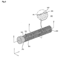
- FIG. 3 illustrates a perspective view of an illuminating device 300.
- the illuminating device 300 may include a light source unit 310 (having a light source), a light pipe 320 and a reflecting cap 330.
- the light source unit 310 may be supplied with power and thus generate light.
- the light generated by the light source unit 310 may be provided to the light pipe 320, which is optically connected to the light source unit 310.
- the optical film 322 disposed inside a supporter 324 may have a patterned surface on which a plurality of prisms are formed.
- the patterned surface may include a plurality of peaks and a plurality of valleys formed from the plurality of valleys.
- the optical film 322 may be rolled up into a cylinder-shape having a substantially same length as the supporter 324 and having a hollow conduit (or area) extending along a longitudinal array (or direction) of the prisms (i.e., a Y direction).
- the optical film 322 may therefore be provided in a rolled shape (either fully rolled or partially rolled).
- the light generated by the light source unit 310 may travel along a longitudinal direction of the light pipe 320 by being totally reflected by the optical film 322.
- an amount of light may be less in a portion of the light pipe 320 distant from the light source unit 310 than in a portion of the light pipe 320 less distant from the light source unit 310.
- luminance of the light pipe 320 may become lower as it becomes more distant from the light source unit 310.
- At least one of an outer surface and an inner surface of the supporter 324 may be surface-treated. Scattered reflection and scattering of the light generated by the light source unit 310 may be induced and thus light may be uniformly emitted across the whole light pipe 320.
- At least one of the outer surface and the inner surface of the supporter 324 may be surface-treated through injection, extrusion, thermal curing, ultraviolet (UV) curing, molding or roll processing so that a plurality of protrusions 340 and/or a plurality of indentations 350 can be formed on the supporter 324.
- at least one of the outer surface and the inner surface of the supporter 324 may be surface-treated by pressing a roll or a plate engraved with a plurality of protrusions and/or a plurality of indentations down on a surface of the supporter 324 so as to transfer the protrusions and/or the indentations of the roll or plate to the supporter 324.
- At least one of the outer surface and the inner surface of the supporter 324 may be surface-treated by injecting resin into a panel-type mold engraved with a plurality of protrusions and/or a plurality of indentations and curing the resin.
- the surface treatment of the supporter 324 may be performed in various manners other than those set forth herein.
- a density of the protrusions 340 and/or the indentations 350 may increase according to distance from the light source unit 310.
- FIG. 4 illustrates a perspective view of an illuminating device according to an example embodiment of the present invention.
- Other embodiments and configurations are also within the scope of the present invention.
- only the plurality of protrusions 340 may be formed on the surface of the supporter 324 of the light pipe 320.
- only a plurality of indentations may be formed on the surface of the supporter 324 of the light pipe 320.
- a supporter having the plurality of protrusions 340 and/or the plurality of indentations 350 may have a predetermined surface roughness.
- Surface roughness is a measure of surface irregularities.
- the maximum surface roughness of the supporter 324 which means a peak-to-valley (PV) surface roughness of the supporter 324, may indicate a maximum of differences between heights of the protrusions 340 (or peaks) and depths of the indentations 350 (or valleys). Stated differently, surface roughness may be based on a height distance of one protrusion (or peak) on the surface of the supporter and a depth distance of one indentation (or valley) on the surface of the supporter.
- FIG. 5 illustrates a cross-sectional view taken along line A-A' of FIG. 3 .
- the light source unit 310 may include a light source 312 that generates light, a reflective mirror 314 disposed at a rear of the light source 312, and a housing 316 that holds the light source 312 and the reflective mirror 314.
- the light source 312 may be supplied with power by an external power source, and thus may generate light.
- Examples of the light source 312 may include a halogen lamp, a light-emitting diode (LED), a metal halide lamp and a plasma lighting source.
- the reflective mirror 314 may be disposed at a rear of the light source 312.
- the reflective mirror 314 may reflect light generated by the light source 312 and thus may make the light generated by the light 312 incident into the light pipe 320.
- the structure of the reflective mirror 314 may be altered according to length of the light pipe 320.
- the reflective mirror 314 may be formed as an aspherical reflective mirror.
- the reflective mirror 314 may be formed of a material (such as a metal or a plastic material) that can be easily processed.
- the surface of the reflective mirror 314 may be coated with a film that is formed of a highly-reflective metal material such as aluminum or silver.
- the housing 316 may have an empty space therein and may thus hold the light source 312 and the reflective mirror 314 therein.
- the housing 316 may be formed of a material (such as a metal) that is highly rigid, heat-resistant, and can be easily processed.
- Light generated by the light source unit 310 may be incident into the light pipe 320.
- the light pipe 320 may not only transmit the light generated by the light source unit 310 in a longitudinal direction of the light pipe 320 but may also distribute the light generated by the light source unit 310 to outside the illuminating device 300.
- the light pipe 320 may include the optical film 322 and the supporter 324.
- the optical film 322 may have a patterned surface on which a plurality of prisms are formed.
- the surface may be patterned to have a plurality of peaks and a plurality of valleys formed from the plurality of peaks.
- the optical film 322 may have substantially a same length as the supporter 324 and may be rolled up into a cylinder-shape having a hollow conduit (or area) 380.
- the optical film 322 may be provided in a rolled shape (either fully rolled or partially rolled).
- the optical film 322 may be formed of a thermoplastic material with high optical transmittance and well-balanced mechanical, heat-resistant and electrical properties.
- the optical film 322 may be formed of polymethyl metacrylate (PMMA), polyethylene terephthalate (PET) or polycarbonate (PC).
- the optical film 322 may have a patterned surface on which a plurality of prisms are formed.
- the prisms of the optical film 322 may be formed as inequilateral triangles, isosceles triangles, trapezoids or regular triangles, for example. More specifically, the prisms of the optical film 322 may be formed as isosceles triangles having an angle of approximately 90 degrees.
- the supporter 324 may be provided outside of the optical film 322.
- the supporter 324 may surround the optical film 322.
- the supporter 324 may be formed through coating, extrusion, injection, molding or roll processing.
- the supporter 324 may be formed by forming a film through coating, extrusion, molding, injection or roll processing and then rolling up (or partially rolling up) the film into a cylinder-shape.
- the supporter 324 may be formed by forming a cylinder-shape through extrusion.
- the supporter 324 may be formed using various methods, other than those set forth herein.
- the supporter 324 may be formed of a thermoplastic resin material with high optical transmittance and excellent mechanical, heat-resistant and electrical properties.
- the supporter 324 may be formed of polymethyl metacrylate (PMMA), polycarbonate or polyethylene terephthalate (PET).
- PMMA polymethyl metacrylate
- PET polyethylene terephthalate
- the supporter 324 may be formed of PMMA because PMMA is highly rigid and is thus rarely broken and deformed.
- At least one of the outer surface and the inner surface of the supporter 324 may be surface-treated so that the plurality of protrusions 340, the plurality of indentations 350 or both can be formed on the supporter 324.
- light may uniformly emit from the light pipe 320 by inducing scattered reflection and scattering of light generated by the light source 312 of the light source unit 310.
- Density of the protrusions 340 and/or the indentations 350 may increase according to distance from the light source unit 310. Light scattering may increase according to distance from the light source unit 310. Therefore, light may uniformly emit from the whole light pipe 320.
- the protrusions 340 and/or the indentations 350 may be formed through injection, extrusion, thermal curing, UV curing, molding or roll processing.
- the protrusions 340 and/or the indentations 350 may be formed by performing surface treatment on the supporter 324. Once the supporter 324 is surface-treated, the supporter 324 may have a predetermined surface roughness.
- Surface roughness is a measure of surface irregularities.
- the maximum surface roughness of the supporter 324 i.e., the peak-valley (P-V) surface roughness of the supporter 324) may indicate a maximum of differences between heights of the protrusions 340 (or peaks) and depths of the indentations 350 (or valleys). Stated differently, surface roughness may be based on a height distance of one protrusion (or peak) on the surface of the supporter and a depth distance of one indentation (or valley) on the surface of the supporter.
- Table 1 shows a relationship between surface roughness of the supporter 324 and surface illuminance and optical transmittance of the light pipe 320.
- x and o and ⁇ represent bad, good and excellent states.
- Table 1 P-V Surface Roughness Surface Illuminance of A Portion (cd/m 2 ) Surface Illuminance of B Portion (cd/ m 2 ) Optical Transmittance 2 ⁇ m 11000 5000 ⁇ 3 ⁇ m 6000 5450 ⁇ 4 ⁇ m 5900 5450 ⁇ 10 ⁇ m 5800 5470 ⁇ 20 ⁇ m 5700 5490 ⁇ 27 ⁇ m 5620 5500 ⁇ 28 ⁇ m 5600 5500 ⁇ 30 ⁇ m 5500 5500 ⁇ 31 ⁇ m 5400 5400 ⁇
- the scattered reflection performance of the supporter 324 may deteriorate, and thus a difference between the surface illuminance (i.e., the surface illuminance at portion A) at an end of the light pipe 320 near the light source unit 310 and the surface illuminance (i.e., the surface illuminance at portion B) at the other end of the light pipe 320 distant from the light source unit 310 may increase. Therefore, light may uniformly emit from the whole light pipe 320.
- the supporter 324 has a surface roughness of more than 30 ⁇ m, transmission of light may deteriorate in both portions A and B, and thus the light pipe 320 may not effectively emit light.
- the supporter 324 may have a surface roughness of approximately 3 ⁇ m to approximately 30 ⁇ m.
- the light pipe 320 may effectively transmit light from one end of the light pipe 320 to the other end of the light pipe 320, and the optical transmittance of the light pipe 320 may increase.
- a surface illuminance at portion B (i.e., the other end of the light pipe 320 distant from the light source unit 310) of the light pipe 320 may be within a range of approximately 0 to 450 cd/m 2
- a ratio of the surface illuminance at portion A to the illuminance at portion B may be within the range of approximately 1:09 to 1:1.
- One of the outer surface or the inner surface of the supporter 324 may be surface-treated.
- the outer surface and the inner surface of the supporter 324 may both be surface-treated.
- the protrusions 340, the indentations 350 or both may be formed as one integral body with the supporter 324 by surface-treating the supporter 324.
- the reflecting cap 330 may include a cap portion 334 and a reflector 332 that is disposed in the cap portion 334.
- the reflector 332 may be disposed at an end of the light pipe 320 and the reflector 322 may reflect light transmitted through the light pipe 320.
- the surface of the reflector 332 may be coated with a highly-reflective metal material such as aluminum or silver.
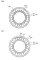
- FIG. 6 illustrates a cross-sectional view taken along line B-B' of FIG. 3 .
- the optical film 322 may be rolled up into a cylinder-shape having the hollow conduit 380 as shown in FIG. 6 .
- An outer surface of the optical film 322 may be patterned, as shown in FIG. 6 .
- an inner surface of the optical film 322 may be patterned.
- One surface of the optical film 322 may be patterned by forming a linear array of prisms, whereas the other surface of the optical film 322 may be substantially smooth or flat. More specifically, a plurality of prisms may be formed on one surface of the optical film 322.
- the prisms of the optical film 322 may be formed as inequilateral triangles, isosceles triangles, trapezoids or regular triangles, for example.
- the prisms of the optical film 322 may be formed as isosceles triangles having an angle of approximately 90 degrees.
- the supporter 324 may be provided outside of the optical film 322.
- the supporter 324 may surround the optical film 322 and may thus protect the optical film 322 against external shock, for example.
- One of the outer surface and the inner surface of the supporter 324 may be surface-treated through injection, extrusion, thermal curing, UV curing, molding, or roll processing so that the protrusions 340, the indentations 350 or both can be formed on the supporter 324. Due to the protrusions 340 and/or the indentations 350, light may be uniformly emitted from the whole light pipe 320 by inducing scattered reflection of light generated by the light source 312 of the light source unit 310.
- FIG. 7 illustrates a cross-sectional view taken along line B-B' of FIG. 3 .
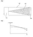
- FIG. 8 illustrates a plan view of the illuminating device 300 shown in FIG. 3 .
- the light pipe 320 is shown in FIG. 8 as having an even surface.
- the illuminating device 300 may also include at least one of a reflector 360 and an extractor 370 that are each disposed between the optical film 322 and the supporter 324.
- the reflector 360 may reflect light so that light can be emitted from the light pipe 320 in only a predetermined direction.
- the extractor 370 may change an angle of light totally-reflected in the light pipe 320 so that the light can be emitted from the light pipe 320 rather than being totally reflected any longer.
- a width of the extractor 370 may become larger as it becomes distant from the light source unit 310.
- an amount of light emitted from a portion of the light pipe 320 distant from the light source unit 310 may be greater than an amount of light emitted from a portion of the light pipe 320 less distant from the light source unit 310. Therefore, the light pipe 320 may uniformly emit light.
- FIG. 9 illustrates a diagram for comparing illuminance of a light pipe A including a surface-treated supporter and illuminance of a light pipe B including a non-surface-treated supporter.
- the light pipe A may have a relatively low surface illuminance near a light source unit, but surface illuminance of the light pipe A may not vary much according to distance from the light source unit.
- the light pipe B may have a relatively high surface illuminance near a light source unit, but the surface illuminance of the light pipe B may gradually decrease according to distance from the light source unit.
- light may be uniformly emitted from a whole light pipe by forming a plurality of protrusions and/or a plurality of indentations on either an outer surface or an inner surface of the supporter 324 through injection, extrusion, thermal curing, or UV curing.
- the supporter 324 may have a surface roughness of approximately 3-30 ⁇ m If the supporter 324 has a surface roughness of less than approximately 3 ⁇ m, then scattered reflection performance of the supporter 324 may deteriorate, and thus the light pipe 320 may not uniformly emit light. On the other hand, if the supporter 324 has a surface roughness of more than approximately 30 ⁇ m, optical transmittance of the supporter 324 may deteriorate.
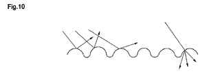
- FIG. 10 illustrates a diagram for explaining optical properties of a surface-treated supporter.
- a surface-treated supporter may cause scattered reflection and scattering of light. When light strikes a rough or granular surface, the light may bounce off in all directions by being reflected from the surface. This phenomenon may be referred to as scattered reflection. When light collides with particles, the light may bounce off in all directions. This phenomenon may be referred to as scattering.
- trajectory of light incident upon the light pipe may vary.
- the incident light may be totally reflected and may thus deviate from its original trajectory.
- the incident light may be scattered and may thus be emitted toward outside of the light pipe.
- the protrusions and/or the indentations may be formed densely in a region near a reflecting cap at which only a small amount of light arrives rather than in a region near a light source unit at which a relatively large amount of light arrives. In this case, light may uniformly emit from a whole light pipe.
- the protrusions and/or the indentations may be formed on either an outer surface or an inner surface of a supporter of a light pipe. Alternatively, the protrusions and/or the indentations may be formed on both the outer surface and the inner surface of a supporter of a light pipe.
- Embodiments of the present invention may provide a light pipe that includes a surface-treated supporter and can thus uniformly emit light across a longitudinal direction of the light pipe.
- a light pipe may be provided that includes an optical film that is rolled (or in a rolled shape) to have a hollow conduit and a supporter surrounding the optical film.
- the supporter may have at least one of a protrusion and an indentation.
- the surface roughness of the supporter may range from approximately 3 ⁇ m to approximately 30 ⁇ m.
- An illuminating device may be provided that includes a light source, a light pipe transmitting and distributing a light from the light source, and a supporter surrounding the optical film.
- the supporter may have at least one of a protrusion and an indentation.
- the optical film may be rolled (or in a rolled shape) to have a hollow conduit.
- the surface roughness of the supporter may range from approximately 3 ⁇ m to approximately 30 ⁇ m.
- any reference in this specification to "one embodiment,” “an embodiment,” “example embodiment,” etc. means that a particular feature, structure, or characteristic described in connection with the embodiment is included in at least one embodiment of the invention.
- the appearances of such phrases in various places in the specification are not necessarily all referring to the same embodiment.
Landscapes
- Physics & Mathematics (AREA)
- General Physics & Mathematics (AREA)
- Optics & Photonics (AREA)
- Planar Illumination Modules (AREA)
- Non-Portable Lighting Devices Or Systems Thereof (AREA)
- Light Guides In General And Applications Therefor (AREA)
Applications Claiming Priority (1)
| Application Number | Priority Date | Filing Date | Title |
|---|---|---|---|
| KR1020080042170A KR100988621B1 (ko) | 2008-05-07 | 2008-05-07 | 광 파이프 및 이를 구비한 조명장치 |
Publications (2)
| Publication Number | Publication Date |
|---|---|
| EP2116875A2 true EP2116875A2 (fr) | 2009-11-11 |
| EP2116875A3 EP2116875A3 (fr) | 2009-11-25 |
Family
ID=40853812
Family Applications (1)
| Application Number | Title | Priority Date | Filing Date |
|---|---|---|---|
| EP08019379A Withdrawn EP2116875A3 (fr) | 2008-05-07 | 2008-11-05 | Conducteur de lumière et dispositif d'éclairage en disposant |
Country Status (4)
| Country | Link |
|---|---|
| US (1) | US8057073B2 (fr) |
| EP (1) | EP2116875A3 (fr) |
| KR (1) | KR100988621B1 (fr) |
| CN (1) | CN101576234A (fr) |
Families Citing this family (17)
| Publication number | Priority date | Publication date | Assignee | Title |
|---|---|---|---|---|
| TW201100716A (en) * | 2009-06-19 | 2011-01-01 | Up Key Trading Co Ltd | Secondary optical lamp shade |
| US8545062B2 (en) * | 2009-12-08 | 2013-10-01 | Industrial Technology Research Institute | Light uniformization structure and light emitting module |
| US20110134646A1 (en) * | 2009-12-08 | 2011-06-09 | Industrial Technology Research Institute | Light uniformization structure and light emitting module |
| US8613534B2 (en) * | 2010-03-12 | 2013-12-24 | Gregory Z. Jigamian | Gun-mounted search light |
| CA2809631A1 (fr) | 2010-09-09 | 2012-03-15 | Energy Focus, Inc. | Systeme d'eclairage allonge |
| TW201248080A (en) * | 2011-05-31 | 2012-12-01 | Lextar Electronics Corp | Light emitting diode lamp |
| WO2013059811A1 (fr) * | 2011-10-21 | 2013-04-25 | Energy Focus, Inc. | Système de distribution de lumière latérale efficace |
| US9004726B2 (en) | 2011-10-27 | 2015-04-14 | Svv Technology Innovations, Inc. | Light directing films |
| TW201326675A (zh) * | 2011-12-19 | 2013-07-01 | Dongguan Masstop Liquid Crystal Display Co Ltd | 照明燈具 |
| KR102022285B1 (ko) * | 2013-01-04 | 2019-09-18 | 삼성전자주식회사 | 스피커 |
| CN105051453A (zh) * | 2013-04-10 | 2015-11-11 | 3M创新有限公司 | 远程照明光导管 |
| WO2015050964A1 (fr) * | 2013-10-03 | 2015-04-09 | 3M Innovative Properties Company | Système d'éclairage à distance |
| WO2015050961A1 (fr) * | 2013-10-03 | 2015-04-09 | 3M Innovative Properties Company | Conduit de lumière d'éclairage à distance |
| US10725236B2 (en) * | 2014-12-23 | 2020-07-28 | Hatbit Illucom Co., Ltd. | Light cylinder, dispenser, and light cylinder manufacturing method |
| CA3015210A1 (fr) | 2016-02-26 | 2017-08-31 | Magic Leap, Inc. | Systeme d'affichage ayant une pluralite de conducteurs de lumiere pour une pluralite d'emetteurs de lumiere |
| CN106024578A (zh) * | 2016-06-30 | 2016-10-12 | 繁昌县奉祥光电科技有限公司 | 一种荧光放电的彩色装饰灯 |
| WO2021087617A1 (fr) * | 2019-11-08 | 2021-05-14 | The University Of British Columbia | Guide de lumière à réseau de cavités optiques linéaires |
Citations (4)
| Publication number | Priority date | Publication date | Assignee | Title |
|---|---|---|---|---|
| JP2001074919A (ja) * | 1999-09-03 | 2001-03-23 | Fuji Photo Film Co Ltd | 光拡散体およびその製造方法 |
| WO2001071396A1 (fr) * | 2000-03-16 | 2001-09-27 | 3M Innovative Properties Company | Guide de lumiere pourvu d"un manchon protecteur |
| EP1775603A1 (fr) * | 2005-10-14 | 2007-04-18 | Minoru Yoshida | Feuille diffusant la lumière et unité de rétroéclairage utilisant cette feuille |
| US20080089654A1 (en) * | 2006-10-13 | 2008-04-17 | Sang Hoon Lee | Light pipe having an improved structure of prisms |
Family Cites Families (30)
| Publication number | Priority date | Publication date | Assignee | Title |
|---|---|---|---|---|
| US4750798A (en) * | 1983-08-29 | 1988-06-14 | Canadian Patents And Developement Limited | Prism light guide luminaire |
| US4615579A (en) | 1983-08-29 | 1986-10-07 | Canadian Patents & Development Ltd. | Prism light guide luminaire |
| CA1279783C (fr) | 1985-11-21 | 1991-02-05 | Minnesota Mining And Manufacturing Company | Pellicule mince et souple reflechissant integralement vers l'interieur |
| US4996632A (en) * | 1988-10-07 | 1991-02-26 | Gulton Industries, Inc. | Multi-color illuminating system |
| KR100225864B1 (ko) * | 1990-06-19 | 1999-10-15 | 요코다 마코도 | 면광원장치 |
| US5258896A (en) * | 1992-06-04 | 1993-11-02 | Minnesota Mining And Manufacturing Company | Line light source |
| IT1271628B (it) | 1994-04-29 | 1997-06-04 | Minnesota Mining & Mfg | Sistema a guida di luce migliorato per strade a traffico veicolare |
| US5700077A (en) * | 1995-03-23 | 1997-12-23 | Minnesota Mining And Manufacturing Company | Line light source including fluorescent colorant |
| DE69622198T2 (de) * | 1995-10-18 | 2003-03-06 | Minnesota Mining & Mfg | Lichtleiter mit totaler interner reflexion |
| US6123442A (en) * | 1997-10-24 | 2000-09-26 | Minnesota Mining And Manufacturing Company | Articles with diffuse reflection of light from light fibers |
| DE29805667U1 (de) | 1998-03-27 | 1998-07-02 | Hemesath, Karl-Heinz, 29313 Hambühren | Blitzleuchte |
| JP3594868B2 (ja) * | 1999-04-26 | 2004-12-02 | 日東電工株式会社 | 積層偏光板及び液晶表示装置 |
| JP3243466B2 (ja) * | 2000-01-21 | 2002-01-07 | 有限会社 トップ電子 | 照明装置 |
| US6612729B1 (en) * | 2000-03-16 | 2003-09-02 | 3M Innovative Properties Company | Illumination device |
| US6481882B1 (en) * | 2000-05-04 | 2002-11-19 | 3M Innovative Properties Company | Light pipe fixture with internal extractor |
| WO2002010803A2 (fr) * | 2000-08-01 | 2002-02-07 | James Cowan | Diffuseur directionnel |
| US6796686B2 (en) * | 2002-10-04 | 2004-09-28 | Tir Systems Ltd. | Color-corrected hollow prismatic light guide luminaire |
| TW200417748A (en) | 2002-11-29 | 2004-09-16 | Kuraray Co | Synthetic resin molded product with excellent light transmission and diffusion capability |
| WO2004068182A2 (fr) * | 2003-01-24 | 2004-08-12 | Digital Optics International Corporation | Systeme d'eclairage haute densite |
| JP4432039B2 (ja) | 2004-04-30 | 2010-03-17 | ミネベア株式会社 | 面状照明装置 |
| KR100527009B1 (ko) | 2005-06-30 | 2005-11-08 | 주식회사 누리플랜 | 형광등 타입 엘이디 조명등 |
| CN2879153Y (zh) | 2005-07-15 | 2007-03-14 | 北京机电研究所 | 一种用于光应力测试的新型光源系统 |
| TWI270992B (en) * | 2005-07-19 | 2007-01-11 | Chi Mei Optoelectronics Corp | Light emitting diode package and light guide pipe and backlight module and liquid crystal display device using the same |
| CN101292178B (zh) | 2005-10-17 | 2011-01-26 | 三菱丽阳株式会社 | 棱镜片及其制造方法以及面光源装置 |
| EP1955099A4 (fr) | 2005-11-30 | 2008-11-05 | 3M Innovative Properties Co | Guide de lumiere et appareil d eclairage comprenant celui-ci |
| US7658514B2 (en) * | 2006-04-13 | 2010-02-09 | Lg Electronics Inc. | Light guide, method and apparatus for manufacturing the same, and illuminating system having the same |
| KR100775839B1 (ko) * | 2006-04-13 | 2007-11-13 | 엘지전자 주식회사 | 중공의 광 파이프 |
| KR20080014387A (ko) | 2006-08-11 | 2008-02-14 | 엘지전자 주식회사 | 확산 입자를 포함하는 광 파이프 및 그 제조 방법 |
| CN201003697Y (zh) | 2007-01-29 | 2008-01-09 | 台湾奈普光电科技股份有限公司 | 直下型背光模块 |
| EP2141521A3 (fr) * | 2008-05-15 | 2010-03-03 | LG Electronics Inc. | Conducteur de lumière et dispositif d'éclairage en disposant |
-
2008
- 2008-05-07 KR KR1020080042170A patent/KR100988621B1/ko not_active Expired - Fee Related
- 2008-11-05 EP EP08019379A patent/EP2116875A3/fr not_active Withdrawn
- 2008-11-10 US US12/267,856 patent/US8057073B2/en active Active
- 2008-12-05 CN CNA2008101829100A patent/CN101576234A/zh active Pending
Patent Citations (4)
| Publication number | Priority date | Publication date | Assignee | Title |
|---|---|---|---|---|
| JP2001074919A (ja) * | 1999-09-03 | 2001-03-23 | Fuji Photo Film Co Ltd | 光拡散体およびその製造方法 |
| WO2001071396A1 (fr) * | 2000-03-16 | 2001-09-27 | 3M Innovative Properties Company | Guide de lumiere pourvu d"un manchon protecteur |
| EP1775603A1 (fr) * | 2005-10-14 | 2007-04-18 | Minoru Yoshida | Feuille diffusant la lumière et unité de rétroéclairage utilisant cette feuille |
| US20080089654A1 (en) * | 2006-10-13 | 2008-04-17 | Sang Hoon Lee | Light pipe having an improved structure of prisms |
Also Published As
| Publication number | Publication date |
|---|---|
| US8057073B2 (en) | 2011-11-15 |
| KR20090116309A (ko) | 2009-11-11 |
| CN101576234A (zh) | 2009-11-11 |
| US20090279302A1 (en) | 2009-11-12 |
| KR100988621B1 (ko) | 2010-10-20 |
| EP2116875A3 (fr) | 2009-11-25 |
Similar Documents
| Publication | Publication Date | Title |
|---|---|---|
| EP2116875A2 (fr) | Conducteur de lumière et dispositif d'éclairage en disposant | |
| US7748874B2 (en) | Light pipe and illuminating device having the same | |
| US7565050B2 (en) | Light pipe having an improved structure of prisms | |
| US8789992B2 (en) | Light pipe and illuminating device having the same | |
| US8075167B2 (en) | Optical film and illuminating device having the same | |
| US7658514B2 (en) | Light guide, method and apparatus for manufacturing the same, and illuminating system having the same | |
| US20140268871A1 (en) | Optics for illumination devices | |
| TWI684049B (zh) | 液晶顯示裝置用光擴散片及液晶顯示裝置用背光單元 | |
| TWI639871B (zh) | 液晶顯示裝置用光學片、液晶顯示裝置用背光單元及液晶顯示裝置用光學片的製造方法 | |
| CN100529809C (zh) | 导光板及使用该导光板的背光模组 | |
| KR100988626B1 (ko) | 광 파이프 및 이를 구비한 조명장치 | |
| US20080037943A1 (en) | Light pipe having a structure of enhancing an emission of a light | |
| KR20090119561A (ko) | 광파이프 및 이를 구비한 조명 장치 | |
| KR101000061B1 (ko) | 광 파이프 및 이를 구비한 조명장치 | |
| KR100988624B1 (ko) | 광 파이프 및 이를 구비한 조명장치 | |
| KR20100073628A (ko) | 광파이프 및 이를 구비한 조명장치 | |
| KR101000059B1 (ko) | 광 파이프 및 이를 구비한 조명장치 | |
| KR100988627B1 (ko) | 광학필름 및 이를 구비한 조명 장치 | |
| KR101028088B1 (ko) | 광 파이프 및 이를 구비한 조명장치 | |
| JP3877293B2 (ja) | 導光シート | |
| KR100958392B1 (ko) | 광 파이프 및 이를 구비한 조명장치 | |
| KR101698004B1 (ko) | 투명 조명 창 |
Legal Events
| Date | Code | Title | Description |
|---|---|---|---|
| PUAI | Public reference made under article 153(3) epc to a published international application that has entered the european phase |
Free format text: ORIGINAL CODE: 0009012 |
|
| PUAL | Search report despatched |
Free format text: ORIGINAL CODE: 0009013 |
|
| 17P | Request for examination filed |
Effective date: 20081105 |
|
| AK | Designated contracting states |
Kind code of ref document: A2 Designated state(s): AT BE BG CH CY CZ DE DK EE ES FI FR GB GR HR HU IE IS IT LI LT LU LV MC MT NL NO PL PT RO SE SI SK TR |
|
| AX | Request for extension of the european patent |
Extension state: AL BA MK RS |
|
| AK | Designated contracting states |
Kind code of ref document: A3 Designated state(s): AT BE BG CH CY CZ DE DK EE ES FI FR GB GR HR HU IE IS IT LI LT LU LV MC MT NL NO PL PT RO SE SI SK TR |
|
| AX | Request for extension of the european patent |
Extension state: AL BA MK RS |
|
| AKX | Designation fees paid |
Designated state(s): DE FR GB NL |
|
| 17Q | First examination report despatched |
Effective date: 20100714 |
|
| STAA | Information on the status of an ep patent application or granted ep patent |
Free format text: STATUS: THE APPLICATION IS DEEMED TO BE WITHDRAWN |
|
| 18D | Application deemed to be withdrawn |
Effective date: 20140311 |