EP2116921A1 - Verfahren zur Bestimmung der Position eines Aufpralls auf der Oberfläche eines Objekts - Google Patents
Verfahren zur Bestimmung der Position eines Aufpralls auf der Oberfläche eines Objekts Download PDFInfo
- Publication number
- EP2116921A1 EP2116921A1 EP08290430A EP08290430A EP2116921A1 EP 2116921 A1 EP2116921 A1 EP 2116921A1 EP 08290430 A EP08290430 A EP 08290430A EP 08290430 A EP08290430 A EP 08290430A EP 2116921 A1 EP2116921 A1 EP 2116921A1
- Authority
- EP
- European Patent Office
- Prior art keywords
- signal
- acoustic signal
- impact
- time
- sensed
- Prior art date
- Legal status (The legal status is an assumption and is not a legal conclusion. Google has not performed a legal analysis and makes no representation as to the accuracy of the status listed.)
- Granted
Links
Images



Classifications
-
- G—PHYSICS
- G01—MEASURING; TESTING
- G01N—INVESTIGATING OR ANALYSING MATERIALS BY DETERMINING THEIR CHEMICAL OR PHYSICAL PROPERTIES
- G01N29/00—Investigating or analysing materials by the use of ultrasonic, sonic or infrasonic waves; Visualisation of the interior of objects by transmitting ultrasonic or sonic waves through the object
- G01N29/44—Processing the detected response signal, e.g. electronic circuits specially adapted therefor
- G01N29/50—Processing the detected response signal, e.g. electronic circuits specially adapted therefor using auto-correlation techniques or cross-correlation techniques
-
- G—PHYSICS
- G06—COMPUTING OR CALCULATING; COUNTING
- G06F—ELECTRIC DIGITAL DATA PROCESSING
- G06F3/00—Input arrangements for transferring data to be processed into a form capable of being handled by the computer; Output arrangements for transferring data from processing unit to output unit, e.g. interface arrangements
- G06F3/01—Input arrangements or combined input and output arrangements for interaction between user and computer
- G06F3/03—Arrangements for converting the position or the displacement of a member into a coded form
- G06F3/041—Digitisers, e.g. for touch screens or touch pads, characterised by the transducing means
- G06F3/043—Digitisers, e.g. for touch screens or touch pads, characterised by the transducing means using propagating acoustic waves
Definitions
- the invention relates to a method for determining the location of an impact on a surface of an object based on the analysis of an acoustic signal generated by the impact.
- ⁇ ijk corresponds to the time difference of arrival of the signal sensed by two different transducers for each area k.
- the localization method is thus based on the presence of a pronounced peak in the sum of the cross-correlation functions at the position where the impact occurred. Nevertheless, under certain circumstances, the determination of the impact location is falsified by spurious contributions arising from reflections of the acoustic signal in the boarder region of the object or some other discontinuities in the object, like a screw, crack or a hole.
- the weighting is carried out in the time domain, for which the best results have been achieved in identifying the location of an impact.
- the signal treatment step can comprise the step of identifying a first wave front of the acoustic signal and a step of applying a damping window.
- the acoustic signal spreads out over the object after an impact and is sensed by a certain number of transforming means, e.g. transducers.
- transforming means e.g. transducers.
- the identification of the first wave front is a robust parameter to identify the part of the signal which should have a higher weight factor than the rest of the sensed signal and which is taken into account by the step of applying the damping window.
- first wave front means the part of the signal which reaches the transforming means without spurious contributions from reflections.
- the step of identifying a first wave front can comprise identifying the maximum signal amplitude.
- the maximum signal amplitude is a parameter which is easily detectable, therefore does not require extensive computational power and, at the same time, is a robust starting parameter for finding out the beginning of the acoustic signal.
- alternative parameters of the sensed acoustic signal could be the power of the signal, the maximum peak to peak amplitude or the energy of the signal.
- a further step of signal rectification and smoothing can be carried out to facilitate the data analysis.
- the step of identifying the first wave front furthermore comprises determining the arrival of the first wave front as the time when the acoustic signal passes a threshold value which is based on the maximum signal amplitude. For example, the arrival of the first wave front of the acoustic signal can be attributed to the time at which a certain percentage of the maximum amplitude is reached.
- ⁇ t ( ⁇ t>0) is a time delay which shifts the starting of the damping window preferably to an earlier time to further optimize the result.
- ⁇ t can be a fixed value or adapted, e.g. on initialization of the device.
- the acoustic signal can be sensed by at least two transforming means, and wherein the first wave front is identified for one, in particular only one, transforming means such that the same time origin of the damping window is applied for all transforming means
- the computational effort can be kept low. Best results were obtained using the first wave front of the first sensed signal.
- the first sensed signal is identified by using a fixed threshold on the signal amplitude of the N channels.
- the acoustic signal can be sensed by at least two transforming means and the weighting of the acoustic signal can be carried out using inter-correlation products of the signals sensed by the at least two transforming means.
- the directly sensed signal is weighted but the inter-correlations which are preferably used to determine the localization of an impact.
- the negative impact of reflections can be suppressed without losing information from the direct signal.
- an inventive variant consists in weighting the sensed signals in a first step like disclosed above, and weighting the intercorrelation products in a second step.
- the step of identifying a first wave front can comprise determining the maximum value of the inter-correlation product.
- the maximum square amplitude, the maximum peak to peak amplitude, the root mean square etc. are robust parameters to identify, as a first approximation, the time difference of arrival of the signal between the two transducers for which the inter-correlation has been determined.
- the step of applying a damping window can comprise applying a symmetrical window function, in particular a Gaussian, Hamming, Hanning or Blackman window to enhance the contribution of the direct signal and to dampen the contribution of the reflections without nevertheless completely losing the content.
- a symmetrical window function in particular a Gaussian, Hamming, Hanning or Blackman window
- the method can further comprise applying low and/or high pass filtering to the acoustic signal which leads to a further optimization of the data from which the impact location can be derived.
- the invention furthermore relates to a computer program product comprising one or more computer readable media having computer-executable instructions for performing the steps of the method of one of the preceding claims.
- the object of the invention is also achieved with the device according to claim 13 with which the same advantageous effects as for the method can be achieved.
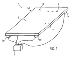
- Figure 1 is a schematic three-dimensional view of a touch-sensitive device 1 using the method for determining the location of an impact according to the invention.
- the touch-sensitive device 1 comprises an interaction means 3, transforming means 5a - 5d (transforming means 5d is not visible in Figure 1 ) and a signal processing means 7 linked to the transforming means 5a - 5d.
- the interaction means 3 is a transparent, semi-transparent or opaque panel which is flat or curved and can be made out of any suitable material, such as leather, latex, silicon, plastic, glass, metal, wood, plasterboard or composite material. It can be rigid or soft as long as acoustic signals can travel therein or thereon.
- the interaction means 3 provides a surface for allowing an interaction between a user and the device 1.
- the user typically provides impacts on the surface side 9 which is opposite to the transforming means, nevertheless, the transforming means 5a - 5d could also be arranged on the side where the impacts occur.
- a touch-sensitive device 1 with four transforming means 5a - 5d is illustrated.
- the transforming means 5a - 5d comprise transducers, like a strain gauges in the form of a piezoelectric transducer like ceramic or PVDF film.
- the transforming means 5a - 5d are not limited to the use of strain gauges, as, in general, any kind of pressure or force sensor being passive or power supplied is suitable, as long as it can transform an acoustic signal generated by an impact is turned into an electrical signal.
- the transforming means 5a - 5d transmit the sensed signal to the signal processing means 7 which is configured to analyse the sensed signal such that the impact location 11 can be determined. Furthermore, the processing means 7 can be configured to output the location 11 of the impact towards an additional device or trigger an action linked to the location on the object where the impact occurred.
- the signal processing means 7 comprises a signal conditioning unit to adapt the sensed signals coming from the transforming means 5a - 5d, for example, by filtering it, amplifying it and/or converting it into a digital signal. This signal is then further treated by the impact location unit which processes the digital signals resulting from an impact on the interaction plate 3 to determine the location (e.g. the x, y coordinates) of this impact on the interaction plate 3.
- the four acoustic transducers 5a - 5d provide sensed signals s i (t), with i from 1 - 4, which are then turned into discrete sensed signals s i (n) by the signal processing means 7 (the signal conditioning unit). Afterwards, a Fourier transform is carried out to obtain S i (w) for each forming means 5a - 5d.
- the signal conditioning unit can eventually also take into account dispersion effects.
- the cross-correlations are re-transformed into the time domain using an inverse Fourier transform.
- the time difference of arrival value ⁇ ijk corresponds to difference in traveling time of the acoustic signal generated by an impact at location k with respect to the position of the transforming means i and j among the means 5a - 5d.
- the value is either theoretically determined or at the initialization or calibration of the device 1.
- the energy maximum of p k (u) is looked for.
- other parameters of the cross-correlation sum can also be used, for example, the maximum value, the power or maximal square amplitude, the maximal peak to peak amplitude, the root means square etc. Further details about this method can be found in the abovementioned prior art document.
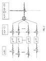
- Figure 2 illustrates a theoretical outcome of the described method.
- the cross-correlation products is illustrated for a given number of transducers, in the middle the cross-correlation is corrected by the time difference of arrival value ⁇ ijk for the location k 0 corresponding to the location 11 of the impact and the right hand side illustrates the sum of the cross-correlation products for position k 0 with the expected pronounced peak.
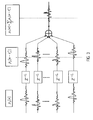
- Figure 3 now illustrates the characterizing value p k (u) when k does not correspond to k 0 .
- the characterizing value p k (u) is much lower than p k0 (u).
- the upper part of Figure 4 illustrates one example of a sensed signal in the theoretical case of a free-field propagation. With no reflection the duration of the signal is limited in time. Now, in the presence of reflections due to non-perfect boundary conditions, the signal spreads out in time (lower part of Figure 4 ). Like illustrated in the lower part of Figure 4 , it is no longer possible to differentiate between the first wave front which directly reaches a transforming means without reflection on the boundaries and the first contributions arising from reflections.
- the acoustic signal as a consequence of the impact on the interaction plate can already have a certain time duration so that the end of the direct sensed signal can interfere with the beginning of the reflected signal. Furthermore dispersion effects further smear out of the signal.
- FIG. 5 Carrying out the method of determining the location of an impact as described above on the sensed signal comprising the spurious contributions, a result as illustrated in Figure 5 is obtained.
- the three dimensional plot illustrates p k (u) as a function of the coordinates x, y of the positions k on the interaction plate 3. Due to the falsified signals, the sum of the cross-correlation product 51 corresponding to the impact location 11 has a maximum that is less pronounced compared to the one illustrated: in Figure 2 .
- the cross correlation products of some other locations 53, 55, 57, 59 not corresponding to the real impact position k 0 are wrongly accentuated by the spurious contributions. Thus it becomes more difficult to identify correctly the location 11 of the impact. In the worst case, even a wrong impact location could be identified by the signal processing means 7.
- the method according to the invention proposes to carry out a weighting of the sensed acoustic signals so that the contributions at the beginning have a higher impact than the signal at the end without, nevertheless, completely removing the tail of the signal.
- the data treatment is carried out in the signal processing means 7 either in the analogue domain, thus inside the signal conditioning unit, prior to carrying out the localization routine or in the digital domain.
- This inventive signal treatment step comprises a first step of identifying a first wave front of the acoustic signal and a second step of applying a damping window.
- the first wave front identification is based on an estimation of the time of arrivals of the signal at each one of the transforming means 5a - 5d.
- the time of arrival estimation in this embodiment is achieved by, first of all, carrying out a full wave rectification and a subsequent smoothing routine by for example applying a first order low-pass filtering on the fully rectified signal.
- the maximum amplitude a i max is determined for each one of the transforming means 5a - 5d.
- the maximum values do not necessarily correspond to the time of arrival of the first wave front, however, it has been found out that it corresponds to a robust parameter from which the time of arrival can be estimated. For this purpose it is determined when the signal first reaches a given percentage of this maximum level. This point in time is then considered to represent the time of arrival of the acoustic signal at the transforming means. Thus, the time of arrival corresponds to the time n i (in a discrete signal regime (n)) for which the signal reaches ⁇ x a i max with 0 ⁇ 1. Best results have been achieved for ⁇ being in range of 0.15 to 0.20, preferably 0.15.
- Figure 6 showing a fully rectified and smoothed signal in which the maximum amplitude A i max and the time of arrival at the time ni corresponding to ⁇ x A i max is also indicated.
- the second step of applying a damping window then consists in multiplying the sensed signals with a suitable damping window, preferably an exponential window like illustrated in Figure 7 in dotted lines.
- the exponential window could start with the time index n i corresponding to the time of arrival, however, best results have been achieved when the damping window starts earlier than the time of arrival.
- ⁇ t corresponds to a positive value and T is the exponential time constant.
- w(n) exp((n i - ⁇ n - n)/N).
- N T/Ts and where Ts is the sampling period and T the exponential time constant.
- the time of arrival determination is possible to limit the time of arrival determination to only one of the transforming means, in particular to the one where the signal is observed first.
- the computational effort can be limited and the damping window can start at the same time t i or t i - ⁇ t for all sensed signals.
- the exponential damping window is only one inventive example, other kinds of damping windows can also be used indeed, any kind of damping window can be used and which is either non-symmetrical, e.g. linear, or symmetrical, e.g. Gaussian, Blackman, Hanning or Hamming. In case of a symmetrical window this could be centered around t i - ⁇ t. This would prevent from inadvertently cancelling the first wave front on the sensed signal.
- the method for weighting the acoustic signal is carried out on the inter-correlation product of the signals sensed by the transforming means 5a - 5d as described above.
- a damping window preferably a symmetrical one, like a Gaussian, Hamming, Hanning or Blackman window, is used to enhance the contribution of the cross-correlation which is attributed to direct signal and to damp the contribution of the signals arising from reflections.
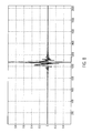
- Figure 8 illustrate the concept of this second embodiment. It shows a cross-correlation product calculated out of two sensed signals (plain line).
- the damping window in dotted lines is centered on the maximum of the cross-correlation product.
- Figure 9 illustrates the effect of the weighting of the cross correlated product which is then used to identify the location of the impact.
- the first and second embodiments of the invention can also be combined to further suppress spurious contributions.
- the first and second embodiments can further be improved by applying high and/or low pass filters to remove spurious contributions to the signals, e.g. arising from the power supply etc.
Landscapes
- Engineering & Computer Science (AREA)
- Physics & Mathematics (AREA)
- General Physics & Mathematics (AREA)
- General Engineering & Computer Science (AREA)
- Theoretical Computer Science (AREA)
- Chemical & Material Sciences (AREA)
- Biochemistry (AREA)
- Signal Processing (AREA)
- Health & Medical Sciences (AREA)
- Life Sciences & Earth Sciences (AREA)
- Acoustics & Sound (AREA)
- Analytical Chemistry (AREA)
- Human Computer Interaction (AREA)
- General Health & Medical Sciences (AREA)
- Immunology (AREA)
- Pathology (AREA)
- Measurement Of Velocity Or Position Using Acoustic Or Ultrasonic Waves (AREA)
- Investigating Or Analyzing Materials By The Use Of Ultrasonic Waves (AREA)
- Length Measuring Devices Characterised By Use Of Acoustic Means (AREA)
- Measurement Of Mechanical Vibrations Or Ultrasonic Waves (AREA)
Priority Applications (6)
| Application Number | Priority Date | Filing Date | Title |
|---|---|---|---|
| AT08290430T ATE523839T1 (de) | 2008-05-07 | 2008-05-07 | Verfahren zur bestimmung der position eines aufpralls auf der oberfläche eines objekts |
| EP08290430A EP2116921B1 (de) | 2008-05-07 | 2008-05-07 | Verfahren zur Bestimmung der Position eines Aufpralls auf der Oberfläche eines Objekts |
| JP2008154570A JP4834694B2 (ja) | 2008-05-07 | 2008-06-12 | 物体の表面上の衝撃位置を決定する方法 |
| PCT/EP2009/002903 WO2009135589A1 (en) | 2008-05-07 | 2009-04-21 | Method for determining the location of an impact on a surface of an object |
| CN200980116086.1A CN102016774B (zh) | 2008-05-07 | 2009-04-21 | 确定物体表面上碰撞位置的方法 |
| US12/991,419 US8670290B2 (en) | 2008-05-07 | 2009-04-21 | Method for determining the location of an impact on a surface of an object |
Applications Claiming Priority (1)
| Application Number | Priority Date | Filing Date | Title |
|---|---|---|---|
| EP08290430A EP2116921B1 (de) | 2008-05-07 | 2008-05-07 | Verfahren zur Bestimmung der Position eines Aufpralls auf der Oberfläche eines Objekts |
Publications (2)
| Publication Number | Publication Date |
|---|---|
| EP2116921A1 true EP2116921A1 (de) | 2009-11-11 |
| EP2116921B1 EP2116921B1 (de) | 2011-09-07 |
Family
ID=39745110
Family Applications (1)
| Application Number | Title | Priority Date | Filing Date |
|---|---|---|---|
| EP08290430A Not-in-force EP2116921B1 (de) | 2008-05-07 | 2008-05-07 | Verfahren zur Bestimmung der Position eines Aufpralls auf der Oberfläche eines Objekts |
Country Status (6)
| Country | Link |
|---|---|
| US (1) | US8670290B2 (de) |
| EP (1) | EP2116921B1 (de) |
| JP (1) | JP4834694B2 (de) |
| CN (1) | CN102016774B (de) |
| AT (1) | ATE523839T1 (de) |
| WO (1) | WO2009135589A1 (de) |
Cited By (2)
| Publication number | Priority date | Publication date | Assignee | Title |
|---|---|---|---|---|
| US20110261655A1 (en) * | 2008-05-07 | 2011-10-27 | Sensitive Object SA | Method for Determining the Location of an Impact on a Surface of an Object |
| WO2012069818A1 (en) * | 2010-11-22 | 2012-05-31 | Bpb Limited | Actuator and method of manufacture thereof |
Families Citing this family (32)
| Publication number | Priority date | Publication date | Assignee | Title |
|---|---|---|---|---|
| CN101718862B (zh) * | 2009-11-13 | 2012-03-21 | 浙江大学 | 基于ar模型和小波变换的核电站松动件定位方法 |
| US8941623B2 (en) * | 2010-07-27 | 2015-01-27 | Motorola Mobility Llc | Methods and devices for determining user input location based on device support configuration |
| WO2012019043A1 (en) | 2010-08-06 | 2012-02-09 | Motorola Mobility, Inc. | Methods and devices for determining user input location using acoustic sensing elements |
| US9639213B2 (en) | 2011-04-26 | 2017-05-02 | Sentons Inc. | Using multiple signals to detect touch input |
| US11327599B2 (en) | 2011-04-26 | 2022-05-10 | Sentons Inc. | Identifying a contact type |
| US9189109B2 (en) | 2012-07-18 | 2015-11-17 | Sentons Inc. | Detection of type of object used to provide a touch contact input |
| US10198097B2 (en) | 2011-04-26 | 2019-02-05 | Sentons Inc. | Detecting touch input force |
| US9477350B2 (en) | 2011-04-26 | 2016-10-25 | Sentons Inc. | Method and apparatus for active ultrasonic touch devices |
| GB2493929B (en) * | 2011-08-22 | 2015-11-25 | Bae Systems Plc | Determining impact damage in a composite member by acoustic wave processing |
| TW201316240A (zh) * | 2011-10-06 | 2013-04-16 | Rich Ip Technology Inc | 利用圖形用戶介面影像之觸碰處理方法及系統 |
| KR101771896B1 (ko) | 2011-11-18 | 2017-08-28 | 센톤스 아이엔씨. | 국소형 햅틱 피드백 |
| KR101648143B1 (ko) | 2011-11-18 | 2016-08-16 | 센톤스 아이엔씨. | 터치 입력 힘 검출 |
| US10235004B1 (en) | 2011-11-18 | 2019-03-19 | Sentons Inc. | Touch input detector with an integrated antenna |
| US20150135858A1 (en) * | 2012-05-01 | 2015-05-21 | F.T. Innovation Inc. | Collision position detection device, wind power generation device and wind power generation system |
| US9524063B2 (en) | 2012-07-18 | 2016-12-20 | Sentons Inc. | Detection of a number of touch contacts of a multi-touch input |
| US9513727B2 (en) | 2012-07-18 | 2016-12-06 | Sentons Inc. | Touch input surface microphone |
| US9348468B2 (en) | 2013-06-07 | 2016-05-24 | Sentons Inc. | Detecting multi-touch inputs |
| US9588552B2 (en) | 2013-09-11 | 2017-03-07 | Sentons Inc. | Attaching electrical components using non-conductive adhesive |
| US9459715B1 (en) | 2013-09-20 | 2016-10-04 | Sentons Inc. | Using spectral control in detecting touch input |
| US9880671B2 (en) | 2013-10-08 | 2018-01-30 | Sentons Inc. | Damping vibrational wave reflections |
| DE102014219169A1 (de) * | 2014-09-23 | 2016-03-24 | Fraunhofer-Gesellschaft zur Förderung der angewandten Forschung e.V. | Vibrationsgestützte Trajektorienberechnung einer frei geführten Vorrichtung |
| US10048811B2 (en) | 2015-09-18 | 2018-08-14 | Sentons Inc. | Detecting touch input provided by signal transmitting stylus |
| US10309893B2 (en) * | 2015-12-21 | 2019-06-04 | The Boeing Company | Composite inspection |
| US10345267B2 (en) * | 2015-12-21 | 2019-07-09 | The Boeing Company | Composite inspection |
| US10908741B2 (en) | 2016-11-10 | 2021-02-02 | Sentons Inc. | Touch input detection along device sidewall |
| US10296144B2 (en) | 2016-12-12 | 2019-05-21 | Sentons Inc. | Touch input detection with shared receivers |
| US10126877B1 (en) | 2017-02-01 | 2018-11-13 | Sentons Inc. | Update of reference data for touch input detection |
| US10585522B2 (en) | 2017-02-27 | 2020-03-10 | Sentons Inc. | Detection of non-touch inputs using a signature |
| US11580829B2 (en) | 2017-08-14 | 2023-02-14 | Sentons Inc. | Dynamic feedback for haptics |
| US11009411B2 (en) | 2017-08-14 | 2021-05-18 | Sentons Inc. | Increasing sensitivity of a sensor using an encoded signal |
| JP2019109073A (ja) * | 2017-12-15 | 2019-07-04 | 日本電信電話株式会社 | 検知システム及び検知方法 |
| CN109085248B (zh) * | 2018-07-03 | 2021-04-06 | 内蒙古科技大学 | 承压管道壁冲击源的定位方法、装置及系统 |
Citations (2)
| Publication number | Priority date | Publication date | Assignee | Title |
|---|---|---|---|---|
| WO2003005292A1 (en) * | 2001-07-04 | 2003-01-16 | New Transducers Limited | Contact sensitive device |
| WO2006108443A1 (en) | 2005-04-13 | 2006-10-19 | Sensitive Object | Method for determining the location of impacts by acoustic imaging |
Family Cites Families (11)
| Publication number | Priority date | Publication date | Assignee | Title |
|---|---|---|---|---|
| JPS6217677A (ja) * | 1985-07-17 | 1987-01-26 | Yokogawa Electric Corp | 超音波測定装置 |
| JP2001251224A (ja) * | 2000-03-06 | 2001-09-14 | Nippon Telegr & Teleph Corp <Ntt> | 反響消去方法および反響消去装置 |
| JP2002057632A (ja) * | 2000-08-11 | 2002-02-22 | Japan Radio Co Ltd | キャンセラ |
| JP3695579B2 (ja) * | 2001-03-21 | 2005-09-14 | 財団法人鉄道総合技術研究所 | 震央距離及びマグニチュード推定方法とそのための装置 |
| JP4065946B2 (ja) * | 2003-03-20 | 2008-03-26 | 独立行政法人産業技術総合研究所 | 多成分ae波形の初動検出方法 |
| US7308286B2 (en) * | 2003-11-20 | 2007-12-11 | Telefonaktiebolaget Lm Ericsson (Publ) | Multi-dimensional joint searcher and channel estimators |
| JP4315377B2 (ja) * | 2004-03-15 | 2009-08-19 | 日本無線株式会社 | スペクトラム拡散信号受信装置 |
| WO2006067851A1 (ja) * | 2004-12-24 | 2006-06-29 | Mitsubishi Denki Kabushiki Kaisha | 測位装置および測位装置の位置特定方法 |
| SG136813A1 (en) * | 2006-04-11 | 2007-11-29 | Sony Corp | A method for estimating one or more parameters of a ultra wideband signal and a receiver system for receiving ultra wideband signals |
| GB2438461A (en) * | 2006-05-23 | 2007-11-28 | Univ Cambridge Tech | Weighted phase separation based ultrasonic deformation estimation |
| EP2116921B1 (de) * | 2008-05-07 | 2011-09-07 | Tyco Electronics Services GmbH | Verfahren zur Bestimmung der Position eines Aufpralls auf der Oberfläche eines Objekts |
-
2008
- 2008-05-07 EP EP08290430A patent/EP2116921B1/de not_active Not-in-force
- 2008-05-07 AT AT08290430T patent/ATE523839T1/de not_active IP Right Cessation
- 2008-06-12 JP JP2008154570A patent/JP4834694B2/ja not_active Expired - Fee Related
-
2009
- 2009-04-21 US US12/991,419 patent/US8670290B2/en not_active Expired - Fee Related
- 2009-04-21 CN CN200980116086.1A patent/CN102016774B/zh not_active Expired - Fee Related
- 2009-04-21 WO PCT/EP2009/002903 patent/WO2009135589A1/en not_active Ceased
Patent Citations (2)
| Publication number | Priority date | Publication date | Assignee | Title |
|---|---|---|---|---|
| WO2003005292A1 (en) * | 2001-07-04 | 2003-01-16 | New Transducers Limited | Contact sensitive device |
| WO2006108443A1 (en) | 2005-04-13 | 2006-10-19 | Sensitive Object | Method for determining the location of impacts by acoustic imaging |
Cited By (6)
| Publication number | Priority date | Publication date | Assignee | Title |
|---|---|---|---|---|
| US20110261655A1 (en) * | 2008-05-07 | 2011-10-27 | Sensitive Object SA | Method for Determining the Location of an Impact on a Surface of an Object |
| US8670290B2 (en) * | 2008-05-07 | 2014-03-11 | Elo Touch Solutions, Inc. | Method for determining the location of an impact on a surface of an object |
| WO2012069818A1 (en) * | 2010-11-22 | 2012-05-31 | Bpb Limited | Actuator and method of manufacture thereof |
| CN103314532A (zh) * | 2010-11-22 | 2013-09-18 | 圣-戈贝恩普拉科公司 | 促动器及其制造方法 |
| RU2594952C2 (ru) * | 2010-11-22 | 2016-08-20 | Сэн-Гобэн Плако Сас | Выключатель и способ его изготовления |
| US9813060B2 (en) | 2010-11-22 | 2017-11-07 | Saint-Gobain Placo Sas | Actuator and method of manufacture thereof |
Also Published As
| Publication number | Publication date |
|---|---|
| ATE523839T1 (de) | 2011-09-15 |
| US20110261655A1 (en) | 2011-10-27 |
| WO2009135589A1 (en) | 2009-11-12 |
| CN102016774B (zh) | 2014-07-16 |
| JP2009271045A (ja) | 2009-11-19 |
| CN102016774A (zh) | 2011-04-13 |
| JP4834694B2 (ja) | 2011-12-14 |
| US8670290B2 (en) | 2014-03-11 |
| EP2116921B1 (de) | 2011-09-07 |
Similar Documents
| Publication | Publication Date | Title |
|---|---|---|
| EP2116921B1 (de) | Verfahren zur Bestimmung der Position eines Aufpralls auf der Oberfläche eines Objekts | |
| EP2073106B1 (de) | Verfahren zur Bestimmung der Positionen mindestens zweier Einschläge | |
| EP1645947B1 (de) | Berührungsempfindliche Vorrichtung | |
| US8392486B2 (en) | Method for determining the position of impacts | |
| EP1869443B1 (de) | Verfahren zur bestimmung von aufprallstellen mittels akustischer bildgebung | |
| CN104181235B (zh) | 一种基于虚拟时间反转的声发射被动成像方法和装置 | |
| EP2903530B1 (de) | Scherwellenabschwächung aus k-raum-analysesystem | |
| CN112945442B (zh) | 一种基于压电-导波阵列的大面积结构冲击成像方法 | |
| CN111624252A (zh) | 一种提高Lamb波相控阵聚焦检测速度的方法 | |
| KR20170124279A (ko) | 수중 방사 소음 측정시 외부표적 소음 제거가 가능한 신호처리 방법 및 장치 | |
| Kehlenbach et al. | Identifying damage in plates by analyzing Lamb wave propagation characteristics | |
| KR20110060183A (ko) | 로봇 플랫폼에 의해 발생한 반사파 제거 신호처리 장치 및 방법 | |
| CN104215944A (zh) | 一种基于参数选择的雷达海杂波自适应抑制处理方法 | |
| CN103185881B (zh) | 基于波导不变量的混响抑制方法 | |
| Hamstad | On lamb modes as a function of acoustic emission source rise time. | |
| Hafizi et al. | An investigation of acoustic emission signal attenuation for monitoring of progressive failure in fiberglass reinforced composite laminates | |
| US7289391B2 (en) | Narrowband phase difference measurement technique for sonar applications | |
| EP1806593B1 (de) | Bestimmung des entsprechenden Messfensters zur Schallquellenortung in Echoumgebungen | |
| CN116609425A (zh) | 基于超声导波的损伤分类识别方法、装置、系统及介质 | |
| USH2112H1 (en) | Method for measuring coating thickness using ultrasonic spectral tracking | |
| Demirli et al. | A generic parametric model for ultrasonic signal analysis | |
| CN111141829B (zh) | 基于微纳耦合光纤传感器的平面定位方法 | |
| Levine et al. | BOUNDARY REFLECTION COMPENSATION IN GUIDED WAVE BASELINE‐FREE IMAGING | |
| Naik et al. | A labview based time of flight measurements for ultrasonic phased array sensors | |
| Anastasi | Investigating the Use of Ultrasonic Guided Wave Analysis Methods for Detecting and Classifying a Small Notch in a Thin Metallic Plate |
Legal Events
| Date | Code | Title | Description |
|---|---|---|---|
| PUAI | Public reference made under article 153(3) epc to a published international application that has entered the european phase |
Free format text: ORIGINAL CODE: 0009012 |
|
| AK | Designated contracting states |
Kind code of ref document: A1 Designated state(s): AT BE BG CH CY CZ DE DK EE ES FI FR GB GR HR HU IE IS IT LI LT LU LV MC MT NL NO PL PT RO SE SI SK TR |
|
| AX | Request for extension of the european patent |
Extension state: AL BA MK RS |
|
| 17P | Request for examination filed |
Effective date: 20100511 |
|
| 17Q | First examination report despatched |
Effective date: 20100614 |
|
| AKX | Designation fees paid |
Designated state(s): AT BE BG CH CY CZ DE DK EE ES FI FR GB GR HR HU IE IS IT LI LT LU LV MC MT NL NO PL PT RO SE SI SK TR |
|
| 17Q | First examination report despatched |
Effective date: 20100730 |
|
| GRAP | Despatch of communication of intention to grant a patent |
Free format text: ORIGINAL CODE: EPIDOSNIGR1 |
|
| RAP1 | Party data changed (applicant data changed or rights of an application transferred) |
Owner name: TYCO ELECTRONICS SERVICES GMBH |
|
| GRAS | Grant fee paid |
Free format text: ORIGINAL CODE: EPIDOSNIGR3 |
|
| GRAA | (expected) grant |
Free format text: ORIGINAL CODE: 0009210 |
|
| REG | Reference to a national code |
Ref country code: GB Ref legal event code: FG4D |
|
| REG | Reference to a national code |
Ref country code: CH Ref legal event code: EP |
|
| REG | Reference to a national code |
Ref country code: IE Ref legal event code: FG4D |
|
| REG | Reference to a national code |
Ref country code: DE Ref legal event code: R096 Ref document number: 602008009527 Country of ref document: DE Effective date: 20111201 |
|
| REG | Reference to a national code |
Ref country code: NL Ref legal event code: VDEP Effective date: 20110907 |
|
| PG25 | Lapsed in a contracting state [announced via postgrant information from national office to epo] |
Ref country code: LT Free format text: LAPSE BECAUSE OF FAILURE TO SUBMIT A TRANSLATION OF THE DESCRIPTION OR TO PAY THE FEE WITHIN THE PRESCRIBED TIME-LIMIT Effective date: 20110907 Ref country code: NO Free format text: LAPSE BECAUSE OF FAILURE TO SUBMIT A TRANSLATION OF THE DESCRIPTION OR TO PAY THE FEE WITHIN THE PRESCRIBED TIME-LIMIT Effective date: 20111207 Ref country code: SE Free format text: LAPSE BECAUSE OF FAILURE TO SUBMIT A TRANSLATION OF THE DESCRIPTION OR TO PAY THE FEE WITHIN THE PRESCRIBED TIME-LIMIT Effective date: 20110907 Ref country code: HR Free format text: LAPSE BECAUSE OF FAILURE TO SUBMIT A TRANSLATION OF THE DESCRIPTION OR TO PAY THE FEE WITHIN THE PRESCRIBED TIME-LIMIT Effective date: 20110907 Ref country code: FI Free format text: LAPSE BECAUSE OF FAILURE TO SUBMIT A TRANSLATION OF THE DESCRIPTION OR TO PAY THE FEE WITHIN THE PRESCRIBED TIME-LIMIT Effective date: 20110907 |
|
| LTIE | Lt: invalidation of european patent or patent extension |
Effective date: 20110907 |
|
| PG25 | Lapsed in a contracting state [announced via postgrant information from national office to epo] |
Ref country code: LV Free format text: LAPSE BECAUSE OF FAILURE TO SUBMIT A TRANSLATION OF THE DESCRIPTION OR TO PAY THE FEE WITHIN THE PRESCRIBED TIME-LIMIT Effective date: 20110907 Ref country code: GR Free format text: LAPSE BECAUSE OF FAILURE TO SUBMIT A TRANSLATION OF THE DESCRIPTION OR TO PAY THE FEE WITHIN THE PRESCRIBED TIME-LIMIT Effective date: 20111208 Ref country code: CY Free format text: LAPSE BECAUSE OF FAILURE TO SUBMIT A TRANSLATION OF THE DESCRIPTION OR TO PAY THE FEE WITHIN THE PRESCRIBED TIME-LIMIT Effective date: 20110907 Ref country code: AT Free format text: LAPSE BECAUSE OF FAILURE TO SUBMIT A TRANSLATION OF THE DESCRIPTION OR TO PAY THE FEE WITHIN THE PRESCRIBED TIME-LIMIT Effective date: 20110907 Ref country code: SI Free format text: LAPSE BECAUSE OF FAILURE TO SUBMIT A TRANSLATION OF THE DESCRIPTION OR TO PAY THE FEE WITHIN THE PRESCRIBED TIME-LIMIT Effective date: 20110907 |
|
| REG | Reference to a national code |
Ref country code: AT Ref legal event code: MK05 Ref document number: 523839 Country of ref document: AT Kind code of ref document: T Effective date: 20110907 |
|
| PG25 | Lapsed in a contracting state [announced via postgrant information from national office to epo] |
Ref country code: BE Free format text: LAPSE BECAUSE OF FAILURE TO SUBMIT A TRANSLATION OF THE DESCRIPTION OR TO PAY THE FEE WITHIN THE PRESCRIBED TIME-LIMIT Effective date: 20110907 |
|
| PG25 | Lapsed in a contracting state [announced via postgrant information from national office to epo] |
Ref country code: CZ Free format text: LAPSE BECAUSE OF FAILURE TO SUBMIT A TRANSLATION OF THE DESCRIPTION OR TO PAY THE FEE WITHIN THE PRESCRIBED TIME-LIMIT Effective date: 20110907 Ref country code: IS Free format text: LAPSE BECAUSE OF FAILURE TO SUBMIT A TRANSLATION OF THE DESCRIPTION OR TO PAY THE FEE WITHIN THE PRESCRIBED TIME-LIMIT Effective date: 20120107 Ref country code: SK Free format text: LAPSE BECAUSE OF FAILURE TO SUBMIT A TRANSLATION OF THE DESCRIPTION OR TO PAY THE FEE WITHIN THE PRESCRIBED TIME-LIMIT Effective date: 20110907 |
|
| PG25 | Lapsed in a contracting state [announced via postgrant information from national office to epo] |
Ref country code: PT Free format text: LAPSE BECAUSE OF FAILURE TO SUBMIT A TRANSLATION OF THE DESCRIPTION OR TO PAY THE FEE WITHIN THE PRESCRIBED TIME-LIMIT Effective date: 20120109 Ref country code: NL Free format text: LAPSE BECAUSE OF FAILURE TO SUBMIT A TRANSLATION OF THE DESCRIPTION OR TO PAY THE FEE WITHIN THE PRESCRIBED TIME-LIMIT Effective date: 20110907 Ref country code: PL Free format text: LAPSE BECAUSE OF FAILURE TO SUBMIT A TRANSLATION OF THE DESCRIPTION OR TO PAY THE FEE WITHIN THE PRESCRIBED TIME-LIMIT Effective date: 20110907 Ref country code: EE Free format text: LAPSE BECAUSE OF FAILURE TO SUBMIT A TRANSLATION OF THE DESCRIPTION OR TO PAY THE FEE WITHIN THE PRESCRIBED TIME-LIMIT Effective date: 20110907 Ref country code: IT Free format text: LAPSE BECAUSE OF FAILURE TO SUBMIT A TRANSLATION OF THE DESCRIPTION OR TO PAY THE FEE WITHIN THE PRESCRIBED TIME-LIMIT Effective date: 20110907 Ref country code: RO Free format text: LAPSE BECAUSE OF FAILURE TO SUBMIT A TRANSLATION OF THE DESCRIPTION OR TO PAY THE FEE WITHIN THE PRESCRIBED TIME-LIMIT Effective date: 20110907 |
|
| REG | Reference to a national code |
Ref country code: DE Ref legal event code: R097 Ref document number: 602008009527 Country of ref document: DE |
|
| PLBE | No opposition filed within time limit |
Free format text: ORIGINAL CODE: 0009261 |
|
| STAA | Information on the status of an ep patent application or granted ep patent |
Free format text: STATUS: NO OPPOSITION FILED WITHIN TIME LIMIT |
|
| PG25 | Lapsed in a contracting state [announced via postgrant information from national office to epo] |
Ref country code: DK Free format text: LAPSE BECAUSE OF FAILURE TO SUBMIT A TRANSLATION OF THE DESCRIPTION OR TO PAY THE FEE WITHIN THE PRESCRIBED TIME-LIMIT Effective date: 20110907 |
|
| 26N | No opposition filed |
Effective date: 20120611 |
|
| REG | Reference to a national code |
Ref country code: DE Ref legal event code: R082 Ref document number: 602008009527 Country of ref document: DE Representative=s name: GRUENECKER, KINKELDEY, STOCKMAIR & SCHWANHAEUS, DE |
|
| PGFP | Annual fee paid to national office [announced via postgrant information from national office to epo] |
Ref country code: FR Payment date: 20120607 Year of fee payment: 5 Ref country code: GB Payment date: 20120525 Year of fee payment: 5 |
|
| REG | Reference to a national code |
Ref country code: GB Ref legal event code: 732E Free format text: REGISTERED BETWEEN 20120906 AND 20120912 |
|
| REG | Reference to a national code |
Ref country code: DE Ref legal event code: R082 Ref document number: 602008009527 Country of ref document: DE Representative=s name: GRUENECKER, KINKELDEY, STOCKMAIR & SCHWANHAEUS, DE Effective date: 20120820 Ref country code: DE Ref legal event code: R081 Ref document number: 602008009527 Country of ref document: DE Owner name: ELO TOUCH SOLUTIONS, INC. (ORG. N. D. GES. D. , US Free format text: FORMER OWNER: TYCO ELECTRONICS SERVICES GMBH, SCHAFFHAUSEN, CH Effective date: 20120820 Ref country code: DE Ref legal event code: R097 Ref document number: 602008009527 Country of ref document: DE Effective date: 20120611 Ref country code: DE Ref legal event code: R082 Ref document number: 602008009527 Country of ref document: DE Representative=s name: GRUENECKER PATENT- UND RECHTSANWAELTE PARTG MB, DE Effective date: 20120820 |
|
| PG25 | Lapsed in a contracting state [announced via postgrant information from national office to epo] |
Ref country code: MC Free format text: LAPSE BECAUSE OF NON-PAYMENT OF DUE FEES Effective date: 20120531 |
|
| REG | Reference to a national code |
Ref country code: CH Ref legal event code: PL |
|
| PG25 | Lapsed in a contracting state [announced via postgrant information from national office to epo] |
Ref country code: LI Free format text: LAPSE BECAUSE OF NON-PAYMENT OF DUE FEES Effective date: 20120531 Ref country code: CH Free format text: LAPSE BECAUSE OF NON-PAYMENT OF DUE FEES Effective date: 20120531 |
|
| REG | Reference to a national code |
Ref country code: IE Ref legal event code: MM4A |
|
| REG | Reference to a national code |
Ref country code: FR Ref legal event code: TP Owner name: ELO TOUCH SOLUTIONS, INC., US Effective date: 20130128 |
|
| PG25 | Lapsed in a contracting state [announced via postgrant information from national office to epo] |
Ref country code: IE Free format text: LAPSE BECAUSE OF NON-PAYMENT OF DUE FEES Effective date: 20120507 Ref country code: ES Free format text: LAPSE BECAUSE OF FAILURE TO SUBMIT A TRANSLATION OF THE DESCRIPTION OR TO PAY THE FEE WITHIN THE PRESCRIBED TIME-LIMIT Effective date: 20111218 |
|
| PG25 | Lapsed in a contracting state [announced via postgrant information from national office to epo] |
Ref country code: BG Free format text: LAPSE BECAUSE OF FAILURE TO SUBMIT A TRANSLATION OF THE DESCRIPTION OR TO PAY THE FEE WITHIN THE PRESCRIBED TIME-LIMIT Effective date: 20111207 |
|
| PG25 | Lapsed in a contracting state [announced via postgrant information from national office to epo] |
Ref country code: MT Free format text: LAPSE BECAUSE OF FAILURE TO SUBMIT A TRANSLATION OF THE DESCRIPTION OR TO PAY THE FEE WITHIN THE PRESCRIBED TIME-LIMIT Effective date: 20110907 |
|
| GBPC | Gb: european patent ceased through non-payment of renewal fee |
Effective date: 20130507 |
|
| REG | Reference to a national code |
Ref country code: FR Ref legal event code: ST Effective date: 20140131 |
|
| PG25 | Lapsed in a contracting state [announced via postgrant information from national office to epo] |
Ref country code: GB Free format text: LAPSE BECAUSE OF NON-PAYMENT OF DUE FEES Effective date: 20130507 Ref country code: TR Free format text: LAPSE BECAUSE OF FAILURE TO SUBMIT A TRANSLATION OF THE DESCRIPTION OR TO PAY THE FEE WITHIN THE PRESCRIBED TIME-LIMIT Effective date: 20110907 |
|
| PG25 | Lapsed in a contracting state [announced via postgrant information from national office to epo] |
Ref country code: FR Free format text: LAPSE BECAUSE OF NON-PAYMENT OF DUE FEES Effective date: 20130531 Ref country code: LU Free format text: LAPSE BECAUSE OF NON-PAYMENT OF DUE FEES Effective date: 20120507 |
|
| PG25 | Lapsed in a contracting state [announced via postgrant information from national office to epo] |
Ref country code: HU Free format text: LAPSE BECAUSE OF FAILURE TO SUBMIT A TRANSLATION OF THE DESCRIPTION OR TO PAY THE FEE WITHIN THE PRESCRIBED TIME-LIMIT Effective date: 20080507 |
|
| PGFP | Annual fee paid to national office [announced via postgrant information from national office to epo] |
Ref country code: DE Payment date: 20150428 Year of fee payment: 8 |
|
| REG | Reference to a national code |
Ref country code: DE Ref legal event code: R119 Ref document number: 602008009527 Country of ref document: DE |
|
| PG25 | Lapsed in a contracting state [announced via postgrant information from national office to epo] |
Ref country code: DE Free format text: LAPSE BECAUSE OF NON-PAYMENT OF DUE FEES Effective date: 20161201 |