EP2117004A1 - Informationsaufzeichnungs-/-wiedergabeeinrichtung und verfahren - Google Patents
Informationsaufzeichnungs-/-wiedergabeeinrichtung und verfahren Download PDFInfo
- Publication number
- EP2117004A1 EP2117004A1 EP07737438A EP07737438A EP2117004A1 EP 2117004 A1 EP2117004 A1 EP 2117004A1 EP 07737438 A EP07737438 A EP 07737438A EP 07737438 A EP07737438 A EP 07737438A EP 2117004 A1 EP2117004 A1 EP 2117004A1
- Authority
- EP
- European Patent Office
- Prior art keywords
- information
- recording
- probes
- reproducing apparatus
- divided areas
- Prior art date
- Legal status (The legal status is an assumption and is not a legal conclusion. Google has not performed a legal analysis and makes no representation as to the accuracy of the status listed.)
- Granted
Links
Images




Classifications
-
- G—PHYSICS
- G11—INFORMATION STORAGE
- G11B—INFORMATION STORAGE BASED ON RELATIVE MOVEMENT BETWEEN RECORD CARRIER AND TRANSDUCER
- G11B9/00—Recording or reproducing using a method not covered by one of the main groups G11B3/00 - G11B7/00; Record carriers therefor
- G11B9/12—Recording or reproducing using a method not covered by one of the main groups G11B3/00 - G11B7/00; Record carriers therefor using near-field interactions; Record carriers therefor
- G11B9/14—Recording or reproducing using a method not covered by one of the main groups G11B3/00 - G11B7/00; Record carriers therefor using near-field interactions; Record carriers therefor using microscopic probe means, i.e. recording or reproducing by means directly associated with the tip of a microscopic electrical probe as used in Scanning Tunneling Microscopy [STM] or Atomic Force Microscopy [AFM] for inducing physical or electrical perturbations in a recording medium; Record carriers or media specially adapted for such transducing of information
- G11B9/1463—Record carriers for recording or reproduction involving the use of microscopic probe means
- G11B9/1472—Record carriers for recording or reproduction involving the use of microscopic probe means characterised by the form
- G11B9/1481—Auxiliary features, e.g. reference or indexing surfaces
-
- B—PERFORMING OPERATIONS; TRANSPORTING
- B82—NANOTECHNOLOGY
- B82Y—SPECIFIC USES OR APPLICATIONS OF NANOSTRUCTURES; MEASUREMENT OR ANALYSIS OF NANOSTRUCTURES; MANUFACTURE OR TREATMENT OF NANOSTRUCTURES
- B82Y10/00—Nanotechnology for information processing, storage or transmission, e.g. quantum computing or single electron logic
-
- G—PHYSICS
- G11—INFORMATION STORAGE
- G11B—INFORMATION STORAGE BASED ON RELATIVE MOVEMENT BETWEEN RECORD CARRIER AND TRANSDUCER
- G11B9/00—Recording or reproducing using a method not covered by one of the main groups G11B3/00 - G11B7/00; Record carriers therefor
- G11B9/12—Recording or reproducing using a method not covered by one of the main groups G11B3/00 - G11B7/00; Record carriers therefor using near-field interactions; Record carriers therefor
- G11B9/14—Recording or reproducing using a method not covered by one of the main groups G11B3/00 - G11B7/00; Record carriers therefor using near-field interactions; Record carriers therefor using microscopic probe means, i.e. recording or reproducing by means directly associated with the tip of a microscopic electrical probe as used in Scanning Tunneling Microscopy [STM] or Atomic Force Microscopy [AFM] for inducing physical or electrical perturbations in a recording medium; Record carriers or media specially adapted for such transducing of information
- G11B9/1418—Disposition or mounting of heads or record carriers
- G11B9/1427—Disposition or mounting of heads or record carriers with provision for moving the heads or record carriers relatively to each other or for access to indexed parts without effectively imparting a relative movement
- G11B9/1436—Disposition or mounting of heads or record carriers with provision for moving the heads or record carriers relatively to each other or for access to indexed parts without effectively imparting a relative movement with provision for moving the heads or record carriers relatively to each other
- G11B9/1454—Positioning the head or record carrier into or out of operative position or across information tracks; Alignment of the head relative to the surface of the record carrier
Definitions
- the present invention relates to, for example, an information recording / reproducing apparatus for and method of recording information onto a recording medium which is formed of a ferroelectric substance or the like, or reproducing the recorded information, using a plurality of probes arranged in an array form.
- this type of information recording / reproducing apparatus there is an apparatus which brings a plurality of cantilever-type probes into contact with a high-density, small recording medium, thereby reading and/or writing information.
- the information is recorded or reproduced by using the plurality of probes arranged in a direction perpendicular to a scanning direction to scan a plurality of linear information tracks having a predetermined length, in parallel.
- a difference in their thermal expansion coefficients causes a deviation between the information tracks and each probe, which makes it hardly possible to read and/or write the information.
- each of the plurality of probes disposed in the probe array is driven independently (refer to a patent document 1).
- Patent document 1 Japanese Patent Application Laid Open No. Hei 6-195769
- an information recording / reproducing apparatus provided with: a recording medium having a recording surface; a plurality of probes for performing at least one process of information recording and reproduction by scanning a plurality of information tracks in parallel, on the recording surface; a position detecting device for detecting a position of at least one information track by using the probes, in each of a plurality of divided areas obtained by area-dividing the recording surface in a direction crossing the plurality of information tracks and in such a manner that each divided area includes at least one information track; and a tracking control device for performing tracking control on the probes in performing the at least one process, in each of the plurality of divided areas set, on the basis of the detected position of the track.
- the information recording / reproducing apparatus of the present invention at least one process of information recording and reproduction is performed by the plurality of probes scanning the plurality of information tracks in parallel on the recording surface of the recording medium.
- the information recording / reproducing apparatus of the present invention may be any of an apparatus only for information recording, an apparatus only for information reproduction, and an apparatus for both information recording and reproduction.
- the probes and the information tracks are disposed at predetermined intervals, respectively. In order to correctly record or reproduce the information, the probe interval and the information track interval may have values close to each other.
- the recording surface of the recording medium is area-divided (hereinafter simply referred to as "divided", as occasion demands) in the direction crossing the information tracks, and they are treated as the plurality of divided areas each of which includes at least one information track.
- area-dividing the recording surface in a direction crossing the plurality of information tracks means dividing it by a dividing line extending in a direction along the information tracks. At this time, there may be set one or a plurality of dividing lines.
- the "area-dividing" herein does not mean the physical division of the recording medium but is division in terms of control, to regard the recording surface as the plurality of divided areas and to process it.
- the number of the information tracks included in each divided area may be the same or different.
- the position of at least one information track in each area is detected by using the probes.
- the probes are tracking-controlled on the basis of the position, and thus, the information recording and reproduction are performed.
- the position detection of the information track in each divided area as described above is not performed, for example, in a case where the recording medium and a probe array have different thermal expansion coefficients or in similar cases, a deviation occurs between the probe interval and the information track interval due to thermal expansion. Thus, the probes cannot scan the information tracks, thereby likely not performing the correct information recording or reproduction.
- the position of at least one information track is detected in each divided area, and the probes are tracking-controlled on the basis of the detected position.
- the deviation between the probes and the information tracks in an allowable range which allows the correct information recording and reproduction (or without an error) to be performed on the plurality of information tracks existing in the same divided area.
- the relatively small deviation as described above it can be corrected, relatively easily.
- the aforementioned operation can be realized without significantly changing the structure of the apparatus or adding new parts or the like.
- it is possible to simplify or miniaturize the apparatus.
- the information recording / reproducing apparatus of the present invention it is possible to record or reproduce the information, correctly, in the simple structure of the apparatus.
- the information recording / reproducing apparatus of the present invention is further provided with a setting device for setting the plurality of divided areas, the position detecting device detecting the position of the information track in each of the plurality of divided areas set.
- the plurality of divided areas are set by the setting device, and the position of the information track is detected in each of the plurality of areas set.
- the setting of the divided area can be changed as occasion demands, depending on circumstances, such as, for example, reducing the size of the divided area if it is predicted or estimated that the deviation is relatively large, and on the other hand, increasing the size of the divided area if it is predicted or estimated that the deviation is relatively small.
- the divided areas are set as fixed areas in advance, the aforementioned effects by the present invention are properly obtained.
- the information recording / reproducing apparatus of the present invention even if an environment surrounding the apparatus and the status of the apparatus itself are changed in various manners, it is possible to record or reproduce the information, correctly, in the simple structure of the apparatus.
- the setting device sets the plurality of divided areas to be variable in accordance with a value or status of a predetermined type of signal obtained by the scanning of the probes.
- the plurality of divided areas are set to be variable, in accordance with the value or status of the predetermined type of signal obtained by the scanning of the probes.
- the "predetermined type of signal” is, for example, a reproduction signal, a tracking signal, and a signal or the like which indicates an error occurrence rate, jitter, and the like. By recording test data or the like, the value or status of the signal can be obtained before the information recording.
- “set ... to be variable” not only means arbitrarily setting the number, size, or the like of the divided areas (i.e. the number of information tracks included) in the setting, but also includes a case of changing what is set in advance, i.e. what is set in accordance with an individual apparatus specification and a required signal accuracy or the like before or after shipping or in checking. The same meaning shall apply in other aspects shown hereinafter.
- the tracking control of the probes is performed at higher accuracy.
- the information recording / reproducing apparatus in this aspect, even if the quality related to the recording and reproduction varies, it is possible to record or reproduce the information, correctly, in the simple structure of the apparatus.
- the information recording / reproducing apparatus of the present invention is further provided with a detecting device for detecting at least one of a temperature related to the recording medium and a temperature related to the probes, the setting device setting the plurality of divided areas to be variable in accordance with the detected temperature.
- the temperature related to the recording medium and the temperature related to the probes is detected, and the plurality of divided areas are set to be variable in accordance with the detected temperature.
- the temperature may be directly detected for the recording medium and the probes, or the temperature of their support parts or surrounding temperature may be detected.
- the "detection" may be measurement, or it may be calculation.
- the amount of the deviation between the probes and the information tracks caused by the thermal expansion, or the like is predicted from the temperature related to the recording medium and the temperature related to the probes, and the number of the information tracks included in each divided area is changed.
- the temperature related to the recording medium and the temperature related to the probes are detected, it is also possible to respond to a case where there is a temperature difference between the recording medium and the probes due to a difference in heat release between the recording medium and the probes.
- the information recording / reproducing apparatus in this aspect, even if there is a significant difference in thermal expansion between the recording medium and the probe array, it is possible to record or reproduce the information, correctly, in the simple structure of the apparatus.
- the setting device sets the plurality of divided areas to be variable in accordance with an amount of the information.
- the plurality of divided areas are set to be variable in accordance with the amount of the information.
- the number of the information tracks included in each divided area is set in accordance with the amount of the information to be recorded or reproduced.
- the amount of the information to be recorded or reproduced influences the probe scanning number.
- the divided areas in accordance with the probe scanning number, it is possible to make a division into the divided areas to the extent that the deviation does not cause any problem to the recording and reproduction, and it is possible to avoid unnecessarily fine division.
- the information recording / reproducing apparatus in this aspect, whether the amount of the information is large or not, it is possible to record or reproduce the information, correctly, in the simple structure of the apparatus.
- the setting device calculates the number of the information tracks for recording the information on the basis of an amount of the information, and the setting device sets the plurality of divided areas to be variable in accordance with the calculated number of the information tracks.
- the number of the information tracks for recording the information is calculated on the basis of the amount of the information to be recorded or reproduced. Then, the plurality of divided areas are set to be variable in accordance with the number of the information tracks.
- the probe scanning number is possible to calculate the probe scanning number from the number of the information tracks for recording the information to be recorded or reproduced.
- the number of the divided areas on the basis of the probe scanning number, it is possible to make a division into the divided areas to the extent that the deviation does not cause any problem to the recording and reproduction, and it is possible to avoid the unnecessarily fine division.
- the information recording / reproducing apparatus in this aspect, whether the amount of the information is large or not, it is possible to record or reproduce the information, correctly, in the simple structure of the apparatus.
- the position detecting device detects the position of one information track existing on one edge side of the divided area, of the plurality of information tracks, as the position, in each of the plurality of divided areas.
- the position of one information track existing on one edge side of the divided area of the plurality of information tracks is detected in each of the plurality of divided areas.
- the deviation of the probes with respect to the information tracks is, for example, a deviation caused by the thermal expansion
- the deviation with respect to the information tracks existing closer to the edge sides which are away from each other is considered to be larger.
- the information recording / reproducing apparatus in this aspect, even if there is a significant difference in thermal expansion between the recording medium and the probe array, it is possible to record or reproduce the information, correctly, in the simple structure of the apparatus.
- the position detecting device detects the position of one information track existing on a central side of the divided area, of the plurality of information tracks, as the position, in each of the plurality of divided areas.
- the position of one information track existing on the central side of the divided area of the plurality of information tracks is detected in each of the plurality of divided areas.
- the "central side” means a position at which there is at least one information track on the edge side.
- the information recording / reproducing apparatus in this aspect, it is possible to record or reproduce the information, correctly.
- the position of one information track on the edge side of the divided area may be further provided with a monitoring device for monitoring quality of a predetermined type of signal obtained by the probes scanning one or a plurality of information tracks existing on the other edge side located on an opposite side to the one edge, in the divided area, the setting device resetting the plurality of divided areas so that the process is performed again in the information in which the process has been performed on the one or the plurality of information tracks existing on the other edge side, if the monitored quality does not reach a predetermined threshold value, the information recording / reproducing apparatus further provided with a processing control device for controlling the probes to perform the process again on the one or the plurality of information tracks existing on the other edge side, if the plurality of divided areas are reset.
- a monitoring device for monitoring quality of a predetermined type of signal obtained by the probes scanning one or a plurality of information tracks existing on the other edge side located on an opposite side to the one edge, in the divided area
- the setting device resetting the plurality of divided areas so that the
- the quality of the predetermined type of signal obtained by the probes scanning the one or the plurality of information tracks existing on the other edge side located on the opposite side to the one edge in the divided area is monitored, and it is judged whether or not the signal quality reaches the predetermined threshold value. Then, if the signal quality does not reach the predetermined threshold value, the recording or reproducing process is performed on the one or the plurality of information tracks existing on the other edge side before the plurality of divided areas are reset. In other words, the number, size, or the like of the divided areas is changed. If the divided areas are reset, the probes are controlled to perform the process again on the one or the plurality of information tracks existing on the other edge side.
- the deviation likely increases in the information tracks existing on the other edge side which is opposite to the one edge.
- the position of the information track existing on the central side of the divided area may be further provided with a monitoring device for monitoring quality of a predetermined type of signal obtained by the probes scanning one or a plurality of information tracks existing on the other edge side located on an opposite side to the one edge, in the divided area, the setting device resetting the plurality of divided areas so that the process is performed again in the information in which the process has been performed on the one or the plurality of information tracks existing on the other edge side, if the monitored quality does not reach a predetermined threshold value, the information recording / reproducing apparatus further provided with a processing control device for controlling the probes to perform the process again on the one or the plurality of information tracks existing on the other edge side, if the plurality of divided areas are reset.
- a monitoring device for monitoring quality of a predetermined type of signal obtained by the probes scanning one or a plurality of information tracks existing on the other edge side located on an opposite side to the one edge, in the divided area
- the setting device resetting the plurality of divided areas so that
- the quality of the predetermined type of signal obtained by the probes scanning the one or the plurality of information tracks existing on the other edge side located on the opposite side to the one edge in the divided area is monitored, and it is judged whether or not the signal quality reaches the predetermined threshold value. Then, if the signal quality does not reach the predetermined threshold value, the recording or reproducing process is performed on the one or the plurality of information tracks existing on the other edge side before the plurality of divided areas are reset. In other words, the number, size, or the like of the divided areas is changed. If the divided areas are reset, the probes are controlled to perform the process again on the one or the plurality of information tracks existing on the other edge side.
- the deviation likely increases in the information tracks existing on the other edge side which is opposite to the one edge.
- the information recording / reproducing apparatus of the present invention is further provided with a monitoring device for monitoring quality of a predetermined type of signal obtained by the probes scanning, the setting device resetting the plurality of divided areas so that the process is performed again, if the monitored quality does not reach a predetermined threshold value, the information recording / reproducing apparatus further provided with a processing control device for controlling the probes to perform the process again, if the plurality of divided areas are reset.
- the quality of the predetermined type of signal obtained by the probes scanning is monitored, and it is judged whether or not the signal quality reaches the predetermined threshold value. Then, if the signal quality does not reach the predetermined threshold value, the divided areas are reset, and the probes are controlled to perform the information recording or reproducing process.
- the divided areas are reset, and the recording or reproducing process is performed again.
- the recording or reproducing process is performed again.
- the position detecting device detects a servo mark recorded in association with the information track on the recording surface.
- the servo mark recorded in association with the information track is detected by the position detecting device.
- the position detecting device detects the position of the servo mark, instead of or in addition to the position of the information track itself, as the position of the information track.
- the servo marks are recorded in advance at predetermined intervals before the information recording.
- the information recording if not even one information track has been recorded, it is possible to detect the position by using the servo mark and to perform the tracking control on the probes.
- the information tracks are recorded at correct positions, so that it is possible to reduce the deviation between the probes and the information tracks.
- the information recording / reproducing apparatus in this construction, it is possible to reduce the deviation between the probes and the information tracks by using the servo mark, thereby recording or reproducing the information, correctly.
- the information track whose position is detected is an information track only for the tracking control.
- the position of the information track only for the tracking control is detected by the position detecting device.
- the tracking control is performed on the information track only for the tracking control.
- tracking may be performed by using another information track that is not only for the tracking control.
- the information recording / reproducing apparatus By performing the tracking control on the information track only for the tracking control, for example, it is possible to simplify the tracking control process and to improve the accuracy of the tracking control, or the like. Thus, according to the information recording / reproducing apparatus in this aspect, it is possible to record or reproduce the information, correctly, while realizing the simplification or miniaturization of the apparatus.
- an information recording / reproducing method in an information recording / reproducing apparatus provided with: a recording medium having a recording surface; and a plurality of probes for performing at least one process of information recording and reproduction by scanning a plurality of information tracks in parallel, on the recording surface
- the information recording / reproducing method provided with: a position detecting process of detecting a position of at least one information track by using the probes, in each of a plurality of divided areas obtained by area-dividing the recording surface in a direction crossing the plurality of information tracks and in such a manner that each divided area includes at least one information track; a tracking control process of performing tracking control on the probes in performing the at least one process, in each of the plurality of divided areas set, on the basis of the detected position of the track; and a execution process of performing the at least one process by using the probes while performing the tracking control.
- the recording surface of the recording medium is divided in the direction crossing the information tracks, and they are treated as the plurality of divided areas each of which includes at least one information track.
- the position of at least one information track is detected in each area by using the probes.
- the probes are tracking-controlled on the basis of the detected position, and the information recording or reproduction is performed.
- the probes are tracking-controlled on the basis of the position of the information track detected in each area, the probes can scan the information track, correctly.
- the information recording / reproducing method of the present invention it is possible to record or reproduce the information, correctly.
- the information recording / reproducing method of the present invention can adopt the same various aspects as those of the information recording / reproducing apparatus of the present invention described above.
- an information recording / reproducing apparatus for recording information as a polarization direction onto a ferroelectric recording medium will be exemplified, which is one example of the information recording / reproducing apparatus of the present invention.
- FIG. 1 is a plan view showing the structure of an information recording / reproducing apparatus in the first embodiment.
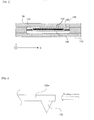
- FIG. 2 is a H-H' cross sectional view.
- FIG. 3 is an enlarged side view showing a probe portion.
- the information recording / reproducing apparatus in the first embodiment is provided with a fixed part 110, a recording medium 120, a probe array 130 having a plurality of probes 135, X-direction actuators 140, X-direction springs 150, Y-direction actuators 160, Y-direction springs 170, and a controller 500.
- the fixed part 110 is a frame for supporting the recording medium 120 and it is fixed to the apparatus.
- the recording medium 120 is formed by supporting a ferroelectric thin film of a PZT (lead zirconate titanate), LiTaO 3 (lithium tantalite), or the like with a plate of silicon or the like.
- a ferroelectric thin film of a PZT lead zirconate titanate
- LiTaO 3 lithium tantalite
- information is recorded on a recording surface formed of the ferroelectric thin film, as linear information tracks which extend in an X direction in FIG. 1 .
- a plurality of servo marks are recorded in advance at predetermined intervals (e.g. at 20nm intervals) in a Y direction in FIG. 1 .
- the probe array 130 is, for example, a glass substrate, and the plurality of probes 130 are disposed on the substrate.
- the probes 135 are disposed in a grid of 10 ⁇ 10, at 1mm intervals. By bringing the probes 135 into contact with the recording medium 120 which is an approximately 10 mm-square, signal is recorded or reproduced.
- the probe 135 is, for example, a probe with a small tip made of silicon.
- the probe 135 is supported by a support part 135a, thereby being formed as a cantilever.
- the probe 135 in addition to performing the information recording or reproduction, the probe 135 also detects the position of the information track on the recording surface of the recording medium 120, as one example of the "position detecting device" of the present invention.
- the X-direction actuators 140, the X-direction springs 150, the Y-direction actuators 160, and the Y-direction springs 170 mutually connect the fixed part 110 and the recording medium 120.
- the recording medium 120 is displaced in the X direction and the Y direction. This changes a relative position between the recording medium 120 and the probes 135.
- the controller 500 includes, for example, an arithmetic circuit, a memory, and the like, and it is electrically connected to the X-direction actuators 140, the Y-direction actuators 160, and the like.
- the controller 500 includes a setting device 510, which is one example of the "setting device” of the present invention; and a tracking control device, which is one example of the "tracking control device” of the present invention.
- the controller 500 sets the recording surface of the recording medium 120 as divided areas, and it drives the X-direction actuators 140 and the Y-direction actuators 160, for tracking control.
- another portion of the apparatus may be also controlled by the controller 500.
- FIG. 4 is a flowchart showing operations in the recording of the information recording / reproducing apparatus in the first embodiment.
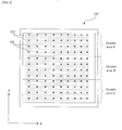
- FIG. 5 is a plan view showing the divided areas on the recording medium.
- the information recording and reproduction can be performed.
- the recording and the reproduction have a difference in operation, caused by whether to output or input the signal; however, other processes or the like until the signal input or output have the same operations. Thus, here, only the recording will be explained.
- a temperature of the recording medium 120 is detected by a thermometer (not illustrated) or the like which is one example of the "detecting device" of the present invention (step S10). Then, in the same manner, a temperature of the probe array 130 is also detected (step S11).
- the temperatures detected here are not necessarily directly detected from the recording medium 120 and the probe array 130 but may be indirectly detected, for example, by detecting members or the like which support them.
- step S12 From the temperatures of the recording medium 120 and the probe array 130, a deviation between the probes 135 and the servo marks caused by their thermal expansion is calculated, and from the deviation, the number m of information tracks (hereinafter referred to as the track number as occasion demands) which can be correctly recorded in one scanning is calculated (step S12).
- the deviation caused by the thermal expansion can be obtained, for example, from the linear expansion coefficients of the recording medium 120 and the probe array 130.
- the recording medium 120 has a linear expansion coefficient of 2.60 ⁇ 10 -6 /deg and the probe array 130 has a linear expansion coefficient of 2.63 ⁇ 10 -6 /deg.
- the probes 135 and the servo marks have a deviation of 0.3 nm between the edge and the edge.
- the track number m can be calculated from the deviation between the probes 135 and the servo marks and from an allowable range of the deviation which allows the correct recording.
- the aforementioned calculation may be performed by an actual arithmetic operation, or it may be performed on the basis of a table prepared in advance.
- a data amount to be recorded is also checked (step S13). Then, the track number n for recording the data to be recorded is calculated from the data amount (step S14).
- the track number n can be obtained, for example, by dividing the data amount to be recorded, by a data amount which can be recorded in one information track.
- the scanning number L for recording is calculated by using them (step S15).
- the scanning number L can be obtained, for example, by dividing the track number n by the track number m.
- the recording surface of the recording medium 120 is divided by three as divided areas A, B, and C.
- the recording surface is equally divided by three; however, it is only necessary to set each divided area to include at least one information track 210, and moreover, the size of the divided areas (i.e. the number of tracks included therein) may be different. Furthermore, the number and size of the divided areas may be sequentially variable in accordance with a change in conditions.
- the deviation between the probes 135 and the servo marks caused by their thermal expansion is 0.3 nm in a temperature change of 1 degree, it will be a deviation of 15 nm in a temperature change of 50 degrees; however, the division by three provides a deviation of 5 nm between the edges of one divided area.
- the assumed operating temperature range of the apparatus is set from 0 degrees Celsius to 50 degrees Celsius, if it is set to have no deviation between the probes 135 and the servo marks at 25 degrees Celsius, then the deviation is only ⁇ 2.5 nm.
- the recording surface as the plurality of divided areas, it is possible to include the deviation between the probes 135 and the servo marks, in the allowable range of the deviation which allows the correct information recording and reproduction (or without an error) to be performed on the plurality of information tracks existing in the same divided area.
- the probes 135 are tracking-controlled for one divided area, and the information is recorded into the divided area (step S18).
- the tracking may be performed on the information track existing on the edge side of the divided area, or the information track existing on the central side.
- a tracking-only track may be provided and the tracking-only track may be tracked.
- the tracking method there can be various options if they allow the tracking of the information tracks 210, such as a wobbling method of tracking the information tracks 210 by wobbling the probes or the information tracks 210 and by using its signal change, and a sample servo method of performing the tracking from a signal in passing through a particular servo mark position.
- step S19 When the recording into the one divided area is ended, it is judged whether or not the recording is ended in all the divided areas (step S19). If the recording is ended in all the divided areas (the step S19: YES), the recording is ended. On the other hand, if there is a divided area which has not been recorded yet (the step S19: NO), it proceeds to a next divided area (step S19a), and the process in the step 18 is performed on the unrecorded divided area. In other words, the recording process is repeated until the unrecorded divided area no longer exists. In this manner, when the information is recorded in all the divided areas, the process is ended.
- the information recording / reproducing apparatus in the embodiment the information can be recorded correctly by dividing the recording surface and performing the tracking control in each divided area.
- the recording was explained, but substantially the same operations are performed when the information is reproduced.
- the unique operations, effects, and the like in the reproduction will be detailed in the following explanation for second and third embodiments.
- FIG. 6 is a flowchart showing operations in the reproduction of the information recording / reproducing apparatus in the second embodiment.
- an explanation will be given on a case where the information recording / reproducing apparatus having the same structure as that of the aforementioned first embodiment reproduces the information.
- a temperature of the recording medium 120 is detected by a thermometer (not illustrated) or the like which is one example of the "detecting device" of the present invention (step S20). Then, in the same manner, a temperature of the probe array 130 is also detected (step S21).
- the temperatures detected here are not necessarily directly detected from the recording medium 120 and the probe array 130 but may be indirectly detected, for example, by detecting members or the like which support them.
- step S22 From the temperatures of the recording medium 120 and the probe array 130, a deviation between the probes 135 and the information tracks 210 caused by their thermal expansion is calculated, and from the deviation, the number m2 of information tracks (hereinafter referred to as the track number as occasion demands) which can be correctly reproduced in one scanning is calculated (step S22).
- the deviation caused by the thermal expansion can be obtained, for example, from the linear expansion coefficients of the recording medium 120 and the probe array 130.
- the aforementioned calculation may be performed by an actual arithmetic operation, or it may be performed on the basis of a table prepared in advance.
- a data amount to be reproduced is also checked (step S23). Then, the track number n2 to be reproduced is calculated from the data amount (step S24).
- the track number n2 can be obtained, for example, by dividing the data amount to be reproduced, by a data amount which can be recorded in one information track.
- the scanning number L2 for reproduction is calculated by using them (step S25).
- the scanning number L2 can be obtained, for example, by dividing the track number n2 by the track number m2.
- the probes 135 are tracking-controlled for one divided area, and the information is reproduced from the divided area (step S28).
- the tracking may be performed on the information track existing on the edge side of the divided area, or the information track existing on the central side.
- a tracking-only track may be provided and the tracking-only track may be tracked.
- the tracking method there can be various options if they allow the tracking of the information tracks 210, such as a wobbling method of tracking the information tracks 210 by wobbling the probes or the information tracks 210 and by using its signal change, and a sample servo method of performing the tracking from a signal in passing through a particular servo mark position.
- the reproduced information may be processed as serial data, or may be outputted after being accumulated in a buffer or the like.
- step S29 When the reproduction from the one divided area is ended, it is judged whether or not the reproduction is ended in all the divided areas (step S29). If the reproduction is ended in all the divided areas (the step S29: YES), the reproduction is ended. On the other hand, if there is a divided area which has not been reproduced yet (the step S29: NO), it proceeds to a next divided area (step S29a), and the process in the step 28 is performed on the unreproduced divided area (or the divided area that has not been reproduced). In other words, the reproducing process is repeated until the unreproduced divided area no longer exists. In this manner, when the information is reproduced in all the divided areas, the process is ended.
- the information recording / reproducing apparatus in the embodiment the information can be reproduced correctly by dividing the recording surface and performing the tracking control in each divided area.
- FIG. 7 is a flowchart showing operations in the reproduction of the information recording / reproducing apparatus in the third embodiment.
- the third embodiment compared to the aforementioned first embodiment, one portion of the operations is different, and the other operations and structure are the same.
- the detection of signal quality or the like which is the different operation will be detailed, and an explanation for the other operations and structure will be omitted.
- the operations in the reproduction will be explained here, as in the second embodiment.
- the controller 500 is provided with a monitoring device which is one example of the "monitoring device" of the present invention, and the quality of the signal obtained by the scanning of the probes 135 is monitored by the monitoring device.
- the signal quality for example, amplitude of the signal, an error rate, a tracking error, a jitter amount, and the like can be used.
- all the information tracks 210 may be monitored, or a particular information track (e.g. information track existing on the edge side of the recording surface) may be monitored.
- the track number m3 can be set, for example, as the number of tracks whose signal quality is normal (i.e. the amplitude, the error rate, and the like are in respective predetermined ranges), of the information tracks 210 in which the signal is obtained by the pre-scanning.
- step S33 a data amount to be reproduced is checked (step S33). Then, the track number n3, in which the data to be reproduced is recorded, is calculated from the data amount (step S34).
- the processes in the step S33 and the step S34 are performed in the same manner as the step S13 and the step S14, respectively.
- the reproduction if an index is recorded in the recording, it is also possible to know the data amount, the recorded position, or the like of the data to be reproduced, by referring to the index.
- the reproduced information may be processed as serial data, or may be outputted after being accumulated in a buffer or the like.
- step S39 When the signal is obtained by the reproduction in the step S38, it is judged whether or not the signal quality is normal (step S39). In other words, even here, the monitoring device monitors the signal quality. Now, if the signal quality is normal (the step S39: YES), the operational flow proceeds to a process in a step S40. If the signal quality is not normal (the step S39: NO), the process in the step S38 is performed again by the controller 500 including a processing control device which is one example of the "processing control device" of the present invention. Here, the tracking is performed on the information track 210 in which the signal is not normal. Thus, it is also possible to obtain the signal with high quality, even from the information track 210 in which the normal signal was not obtained in the first scanning (i.e. the first process in the step S38). Incidentally, the scanning may not be performed on the information track 210 in which the signal quality is normal in the first scanning.
- step S29 it is judged whether or not the reproduction is ended in all the divided areas (step S40). By this, the reproducing process is repeated until the unreproduced divided area no longer exists. In this manner, when the information is reproduced in all the divided areas, the process is ended.
- the information recording / reproducing apparatus in the third embodiment the information can be reproduced correctly by monitoring the signal quality. Moreover, only the reproduction was explained here; however, even when the information is recorded, it is possible to detect the signal quality by pre-recording test data or the like. Thus, the third embodiment can be applied to the information recording.
- the present invention can be applied not only to an information recording / reproducing apparatus which uses the polarization of the ferroelectric substance explained in the aforementioned embodiments but also to an information recording / reproducing apparatus which uses a method of recording information as unevenness into a polymer film, a phase change method of recording information by crystallizing a phase change medium, a near-field recording method using a small optical spot, or the like.
- the present invention can be applied to an information recording / reproducing apparatus or the like for recording information onto a recording medium which is formed of a ferroelectric substance or the like or reproducing the recorded information, using a plurality of probes arranged in an array form.
Landscapes
- Engineering & Computer Science (AREA)
- Chemical & Material Sciences (AREA)
- Nanotechnology (AREA)
- Physics & Mathematics (AREA)
- Mathematical Physics (AREA)
- Theoretical Computer Science (AREA)
- Crystallography & Structural Chemistry (AREA)
- Optical Recording Or Reproduction (AREA)
Applications Claiming Priority (1)
| Application Number | Priority Date | Filing Date | Title |
|---|---|---|---|
| PCT/JP2007/053636 WO2008105071A1 (ja) | 2007-02-27 | 2007-02-27 | 情報記録再生装置及び方法 |
Publications (3)
| Publication Number | Publication Date |
|---|---|
| EP2117004A1 true EP2117004A1 (de) | 2009-11-11 |
| EP2117004A4 EP2117004A4 (de) | 2011-01-05 |
| EP2117004B1 EP2117004B1 (de) | 2013-01-16 |
Family
ID=39720917
Family Applications (1)
| Application Number | Title | Priority Date | Filing Date |
|---|---|---|---|
| EP07737438A Not-in-force EP2117004B1 (de) | 2007-02-27 | 2007-02-27 | Informationsaufzeichnungs-/-wiedergabeeinrichtung und verfahren |
Country Status (4)
| Country | Link |
|---|---|
| US (1) | US8059519B2 (de) |
| EP (1) | EP2117004B1 (de) |
| JP (1) | JP4538087B2 (de) |
| WO (1) | WO2008105071A1 (de) |
Families Citing this family (3)
| Publication number | Priority date | Publication date | Assignee | Title |
|---|---|---|---|---|
| US8004958B2 (en) * | 2006-04-18 | 2011-08-23 | Pioneer Corporation | Information recording/reproducing apparatus |
| US8149680B2 (en) * | 2008-12-31 | 2012-04-03 | Intel Corporation | Random read/write performance of probe storage memory devices |
| CN106921459A (zh) * | 2017-01-16 | 2017-07-04 | 华南理工大学 | 一种基于cdma调制的室内可见光异步定位方法和系统 |
Family Cites Families (13)
| Publication number | Priority date | Publication date | Assignee | Title |
|---|---|---|---|---|
| JP3126409B2 (ja) * | 1991-06-05 | 2001-01-22 | キヤノン株式会社 | 情報記録再生方法 |
| JP3029499B2 (ja) * | 1992-05-07 | 2000-04-04 | キヤノン株式会社 | 記録再生装置 |
| JP3004823B2 (ja) * | 1992-09-03 | 2000-01-31 | キヤノン株式会社 | 情報処理装置 |
| JP3073616B2 (ja) | 1992-12-24 | 2000-08-07 | キヤノン株式会社 | マルチプローブを具備する情報処理装置 |
| JP3652728B2 (ja) | 1994-12-31 | 2005-05-25 | ヒューレット・パッカード・カンパニー | 走査型メモリ装置および誤り訂正方法 |
| US5835477A (en) | 1996-07-10 | 1998-11-10 | International Business Machines Corporation | Mass-storage applications of local probe arrays |
| US7260051B1 (en) | 1998-12-18 | 2007-08-21 | Nanochip, Inc. | Molecular memory medium and molecular memory integrated circuit |
| ATE408880T1 (de) * | 2002-05-23 | 2008-10-15 | Ibm | Speichergerät und verfahren zum abtasten eines speichermediums |
| US7119511B2 (en) | 2003-04-11 | 2006-10-10 | International Business Machines Corporation | Servo system for a two-dimensional micro-electromechanical system (MEMS)-based scanner and method therefor |
| WO2005020226A1 (ja) * | 2003-08-20 | 2005-03-03 | Pioneer Corporation | データ記録再生装置、データ記録再生方法および記録媒体 |
| JP4145773B2 (ja) | 2003-11-06 | 2008-09-03 | パイオニア株式会社 | 情報記録再生装置および記録媒体 |
| US20050286396A1 (en) | 2004-06-24 | 2005-12-29 | Craig Raese | Temperature sensing apparatus and methods for servo and write compensation in a data recording module |
| US7447140B2 (en) * | 2004-07-30 | 2008-11-04 | Seagate Technology Llc | Ferroelectric probe storage apparatus |
-
2007
- 2007-02-27 WO PCT/JP2007/053636 patent/WO2008105071A1/ja not_active Ceased
- 2007-02-27 JP JP2009501074A patent/JP4538087B2/ja not_active Expired - Fee Related
- 2007-02-27 US US12/528,559 patent/US8059519B2/en not_active Expired - Fee Related
- 2007-02-27 EP EP07737438A patent/EP2117004B1/de not_active Not-in-force
Also Published As
| Publication number | Publication date |
|---|---|
| US8059519B2 (en) | 2011-11-15 |
| EP2117004A4 (de) | 2011-01-05 |
| US20100014412A1 (en) | 2010-01-21 |
| JP4538087B2 (ja) | 2010-09-08 |
| WO2008105071A1 (ja) | 2008-09-04 |
| JPWO2008105071A1 (ja) | 2010-06-03 |
| EP2117004B1 (de) | 2013-01-16 |
Similar Documents
| Publication | Publication Date | Title |
|---|---|---|
| US8804270B2 (en) | Tape head actuator | |
| JP2005129216A (ja) | 磁気記憶媒体上にデータトラックを記録するための方法、可変幅のトラックフォーマットで複数のデータトラックを記録するための方法、およびヘッドの位置決めサーボシステム | |
| EP2117004B1 (de) | Informationsaufzeichnungs-/-wiedergabeeinrichtung und verfahren | |
| KR20070105263A (ko) | 디스크 드라이브 및 디스크 드라이브의 제어 방법 | |
| JP2003016748A (ja) | 磁気ディスク装置、モバイル情報機器、及びこれらに適用したサーボ復調制御装置 | |
| JP2010192075A (ja) | 浮上高を調整する方法およびディスクドライブ | |
| US7446977B2 (en) | Recording heads having electrical pads on multiple surfaces | |
| US7365931B2 (en) | Information-recording/reproducing apparatus and method of detecting the gap between a head and a recording medium | |
| US6940683B2 (en) | Matched filter detection for time based servo signals in a tape drive | |
| US7027244B2 (en) | Systems for self-servowriting using write-current variation | |
| JP4256835B2 (ja) | データ記憶装置およびそのトラッキング方法 | |
| JP4277122B2 (ja) | リニアテープドライブ装置 | |
| US7551384B1 (en) | Systems and methods for calibrating a read/write channel of a hard disk drive | |
| US7627778B2 (en) | Prediction-based data reassignment | |
| KR20090131984A (ko) | 서보 기록 방법, 서보 패턴의 위상 편차 보상 방법 및 이를수행하는 하드디스크 드라이브 | |
| US7593180B2 (en) | HDD data read control apparatus, medium, and method | |
| US20120044593A1 (en) | Temperature induced head skew | |
| US20100110849A1 (en) | Information recording/reproducing device and method | |
| JP2008135156A (ja) | マイクロアクチュエータの圧電素子の問題を識別するシステム及び方法 | |
| US20070291402A1 (en) | System and method for generating a position error signal (pes) reference curve in a data storage device | |
| KR20020045544A (ko) | 하드 디스크 드라이브와 그 구동 방법 및 회로 | |
| KR20080005665A (ko) | 하드디스크 드라이브 | |
| CN100412970C (zh) | 检查相位变化类型光记录介质的方法 | |
| US9734862B1 (en) | Method and apparatus for writing test tracks on a magnetic recording medium | |
| US8310781B2 (en) | Disk device |
Legal Events
| Date | Code | Title | Description |
|---|---|---|---|
| PUAI | Public reference made under article 153(3) epc to a published international application that has entered the european phase |
Free format text: ORIGINAL CODE: 0009012 |
|
| 17P | Request for examination filed |
Effective date: 20090831 |
|
| AK | Designated contracting states |
Kind code of ref document: A1 Designated state(s): AT BE BG CH CY CZ DE DK EE ES FI FR GB GR HU IE IS IT LI LT LU LV MC NL PL PT RO SE SI SK TR |
|
| DAX | Request for extension of the european patent (deleted) | ||
| A4 | Supplementary search report drawn up and despatched |
Effective date: 20101203 |
|
| RAP1 | Party data changed (applicant data changed or rights of an application transferred) |
Owner name: PIONEER CORPORATION |
|
| RIC1 | Information provided on ipc code assigned before grant |
Ipc: G11B 9/00 20060101AFI20101129BHEP |
|
| REG | Reference to a national code |
Ref country code: DE Ref legal event code: R079 Ref document number: 602007028081 Country of ref document: DE Free format text: PREVIOUS MAIN CLASS: G11B0009140000 Ipc: G11B0009000000 |
|
| GRAP | Despatch of communication of intention to grant a patent |
Free format text: ORIGINAL CODE: EPIDOSNIGR1 |
|
| RIC1 | Information provided on ipc code assigned before grant |
Ipc: G11B 9/00 20060101AFI20120709BHEP |
|
| GRAS | Grant fee paid |
Free format text: ORIGINAL CODE: EPIDOSNIGR3 |
|
| GRAA | (expected) grant |
Free format text: ORIGINAL CODE: 0009210 |
|
| AK | Designated contracting states |
Kind code of ref document: B1 Designated state(s): AT BE BG CH CY CZ DE DK EE ES FI FR GB GR HU IE IS IT LI LT LU LV MC NL PL PT RO SE SI SK TR |
|
| REG | Reference to a national code |
Ref country code: GB Ref legal event code: FG4D |
|
| REG | Reference to a national code |
Ref country code: CH Ref legal event code: EP |
|
| REG | Reference to a national code |
Ref country code: IE Ref legal event code: FG4D |
|
| REG | Reference to a national code |
Ref country code: AT Ref legal event code: REF Ref document number: 594261 Country of ref document: AT Kind code of ref document: T Effective date: 20130215 Ref country code: CH Ref legal event code: EP |
|
| REG | Reference to a national code |
Ref country code: DE Ref legal event code: R096 Ref document number: 602007028081 Country of ref document: DE Effective date: 20130314 |
|
| PGFP | Annual fee paid to national office [announced via postgrant information from national office to epo] |
Ref country code: GB Payment date: 20130218 Year of fee payment: 7 |
|
| REG | Reference to a national code |
Ref country code: AT Ref legal event code: MK05 Ref document number: 594261 Country of ref document: AT Kind code of ref document: T Effective date: 20130116 |
|
| REG | Reference to a national code |
Ref country code: NL Ref legal event code: VDEP Effective date: 20130116 |
|
| REG | Reference to a national code |
Ref country code: LT Ref legal event code: MG4D |
|
| PG25 | Lapsed in a contracting state [announced via postgrant information from national office to epo] |
Ref country code: BG Free format text: LAPSE BECAUSE OF FAILURE TO SUBMIT A TRANSLATION OF THE DESCRIPTION OR TO PAY THE FEE WITHIN THE PRESCRIBED TIME-LIMIT Effective date: 20130416 Ref country code: BE Free format text: LAPSE BECAUSE OF FAILURE TO SUBMIT A TRANSLATION OF THE DESCRIPTION OR TO PAY THE FEE WITHIN THE PRESCRIBED TIME-LIMIT Effective date: 20130116 Ref country code: LT Free format text: LAPSE BECAUSE OF FAILURE TO SUBMIT A TRANSLATION OF THE DESCRIPTION OR TO PAY THE FEE WITHIN THE PRESCRIBED TIME-LIMIT Effective date: 20130116 Ref country code: IS Free format text: LAPSE BECAUSE OF FAILURE TO SUBMIT A TRANSLATION OF THE DESCRIPTION OR TO PAY THE FEE WITHIN THE PRESCRIBED TIME-LIMIT Effective date: 20130516 Ref country code: SE Free format text: LAPSE BECAUSE OF FAILURE TO SUBMIT A TRANSLATION OF THE DESCRIPTION OR TO PAY THE FEE WITHIN THE PRESCRIBED TIME-LIMIT Effective date: 20130116 Ref country code: AT Free format text: LAPSE BECAUSE OF FAILURE TO SUBMIT A TRANSLATION OF THE DESCRIPTION OR TO PAY THE FEE WITHIN THE PRESCRIBED TIME-LIMIT Effective date: 20130116 Ref country code: ES Free format text: LAPSE BECAUSE OF FAILURE TO SUBMIT A TRANSLATION OF THE DESCRIPTION OR TO PAY THE FEE WITHIN THE PRESCRIBED TIME-LIMIT Effective date: 20130427 |
|
| PG25 | Lapsed in a contracting state [announced via postgrant information from national office to epo] |
Ref country code: FI Free format text: LAPSE BECAUSE OF FAILURE TO SUBMIT A TRANSLATION OF THE DESCRIPTION OR TO PAY THE FEE WITHIN THE PRESCRIBED TIME-LIMIT Effective date: 20130116 Ref country code: PL Free format text: LAPSE BECAUSE OF FAILURE TO SUBMIT A TRANSLATION OF THE DESCRIPTION OR TO PAY THE FEE WITHIN THE PRESCRIBED TIME-LIMIT Effective date: 20130116 Ref country code: GR Free format text: LAPSE BECAUSE OF FAILURE TO SUBMIT A TRANSLATION OF THE DESCRIPTION OR TO PAY THE FEE WITHIN THE PRESCRIBED TIME-LIMIT Effective date: 20130417 Ref country code: NL Free format text: LAPSE BECAUSE OF FAILURE TO SUBMIT A TRANSLATION OF THE DESCRIPTION OR TO PAY THE FEE WITHIN THE PRESCRIBED TIME-LIMIT Effective date: 20130116 Ref country code: SI Free format text: LAPSE BECAUSE OF FAILURE TO SUBMIT A TRANSLATION OF THE DESCRIPTION OR TO PAY THE FEE WITHIN THE PRESCRIBED TIME-LIMIT Effective date: 20130116 Ref country code: PT Free format text: LAPSE BECAUSE OF FAILURE TO SUBMIT A TRANSLATION OF THE DESCRIPTION OR TO PAY THE FEE WITHIN THE PRESCRIBED TIME-LIMIT Effective date: 20130516 Ref country code: LV Free format text: LAPSE BECAUSE OF FAILURE TO SUBMIT A TRANSLATION OF THE DESCRIPTION OR TO PAY THE FEE WITHIN THE PRESCRIBED TIME-LIMIT Effective date: 20130116 |
|
| PG25 | Lapsed in a contracting state [announced via postgrant information from national office to epo] |
Ref country code: MC Free format text: LAPSE BECAUSE OF NON-PAYMENT OF DUE FEES Effective date: 20130228 |
|
| REG | Reference to a national code |
Ref country code: CH Ref legal event code: PL |
|
| PG25 | Lapsed in a contracting state [announced via postgrant information from national office to epo] |
Ref country code: LI Free format text: LAPSE BECAUSE OF NON-PAYMENT OF DUE FEES Effective date: 20130228 Ref country code: EE Free format text: LAPSE BECAUSE OF FAILURE TO SUBMIT A TRANSLATION OF THE DESCRIPTION OR TO PAY THE FEE WITHIN THE PRESCRIBED TIME-LIMIT Effective date: 20130116 Ref country code: RO Free format text: LAPSE BECAUSE OF FAILURE TO SUBMIT A TRANSLATION OF THE DESCRIPTION OR TO PAY THE FEE WITHIN THE PRESCRIBED TIME-LIMIT Effective date: 20130116 Ref country code: CH Free format text: LAPSE BECAUSE OF NON-PAYMENT OF DUE FEES Effective date: 20130228 Ref country code: DK Free format text: LAPSE BECAUSE OF FAILURE TO SUBMIT A TRANSLATION OF THE DESCRIPTION OR TO PAY THE FEE WITHIN THE PRESCRIBED TIME-LIMIT Effective date: 20130116 Ref country code: SK Free format text: LAPSE BECAUSE OF FAILURE TO SUBMIT A TRANSLATION OF THE DESCRIPTION OR TO PAY THE FEE WITHIN THE PRESCRIBED TIME-LIMIT Effective date: 20130116 Ref country code: CZ Free format text: LAPSE BECAUSE OF FAILURE TO SUBMIT A TRANSLATION OF THE DESCRIPTION OR TO PAY THE FEE WITHIN THE PRESCRIBED TIME-LIMIT Effective date: 20130116 |
|
| PLBE | No opposition filed within time limit |
Free format text: ORIGINAL CODE: 0009261 |
|
| REG | Reference to a national code |
Ref country code: FR Ref legal event code: ST Effective date: 20131031 |
|
| STAA | Information on the status of an ep patent application or granted ep patent |
Free format text: STATUS: NO OPPOSITION FILED WITHIN TIME LIMIT |
|
| PG25 | Lapsed in a contracting state [announced via postgrant information from national office to epo] |
Ref country code: CY Free format text: LAPSE BECAUSE OF FAILURE TO SUBMIT A TRANSLATION OF THE DESCRIPTION OR TO PAY THE FEE WITHIN THE PRESCRIBED TIME-LIMIT Effective date: 20130116 |
|
| REG | Reference to a national code |
Ref country code: IE Ref legal event code: MM4A |
|
| REG | Reference to a national code |
Ref country code: DE Ref legal event code: R119 Ref document number: 602007028081 Country of ref document: DE Effective date: 20130903 |
|
| 26N | No opposition filed |
Effective date: 20131017 |
|
| PG25 | Lapsed in a contracting state [announced via postgrant information from national office to epo] |
Ref country code: IT Free format text: LAPSE BECAUSE OF FAILURE TO SUBMIT A TRANSLATION OF THE DESCRIPTION OR TO PAY THE FEE WITHIN THE PRESCRIBED TIME-LIMIT Effective date: 20130116 |
|
| PG25 | Lapsed in a contracting state [announced via postgrant information from national office to epo] |
Ref country code: IE Free format text: LAPSE BECAUSE OF NON-PAYMENT OF DUE FEES Effective date: 20130227 Ref country code: DE Free format text: LAPSE BECAUSE OF NON-PAYMENT OF DUE FEES Effective date: 20130903 Ref country code: FR Free format text: LAPSE BECAUSE OF NON-PAYMENT OF DUE FEES Effective date: 20130318 |
|
| GBPC | Gb: european patent ceased through non-payment of renewal fee |
Effective date: 20140227 |
|
| PG25 | Lapsed in a contracting state [announced via postgrant information from national office to epo] |
Ref country code: GB Free format text: LAPSE BECAUSE OF NON-PAYMENT OF DUE FEES Effective date: 20140227 |
|
| PG25 | Lapsed in a contracting state [announced via postgrant information from national office to epo] |
Ref country code: TR Free format text: LAPSE BECAUSE OF FAILURE TO SUBMIT A TRANSLATION OF THE DESCRIPTION OR TO PAY THE FEE WITHIN THE PRESCRIBED TIME-LIMIT Effective date: 20130116 |
|
| PG25 | Lapsed in a contracting state [announced via postgrant information from national office to epo] |
Ref country code: LU Free format text: LAPSE BECAUSE OF NON-PAYMENT OF DUE FEES Effective date: 20130227 Ref country code: HU Free format text: LAPSE BECAUSE OF FAILURE TO SUBMIT A TRANSLATION OF THE DESCRIPTION OR TO PAY THE FEE WITHIN THE PRESCRIBED TIME-LIMIT; INVALID AB INITIO Effective date: 20070227 |