EP2117100A2 - Convertisseur de mouvements magnétiques - Google Patents
Convertisseur de mouvements magnétiques Download PDFInfo
- Publication number
- EP2117100A2 EP2117100A2 EP09159544A EP09159544A EP2117100A2 EP 2117100 A2 EP2117100 A2 EP 2117100A2 EP 09159544 A EP09159544 A EP 09159544A EP 09159544 A EP09159544 A EP 09159544A EP 2117100 A2 EP2117100 A2 EP 2117100A2
- Authority
- EP
- European Patent Office
- Prior art keywords
- magnet
- magnetic
- rotation
- axis
- motion converter
- Prior art date
- Legal status (The legal status is an assumption and is not a legal conclusion. Google has not performed a legal analysis and makes no representation as to the accuracy of the status listed.)
- Granted
Links
Images




Classifications
-
- H—ELECTRICITY
- H02—GENERATION; CONVERSION OR DISTRIBUTION OF ELECTRIC POWER
- H02K—DYNAMO-ELECTRIC MACHINES
- H02K49/00—Dynamo-electric clutches; Dynamo-electric brakes
- H02K49/10—Dynamo-electric clutches; Dynamo-electric brakes of the permanent-magnet type
-
- H—ELECTRICITY
- H02—GENERATION; CONVERSION OR DISTRIBUTION OF ELECTRIC POWER
- H02K—DYNAMO-ELECTRIC MACHINES
- H02K7/00—Arrangements for handling mechanical energy structurally associated with dynamo-electric machines, e.g. structural association with mechanical driving motors or auxiliary dynamo-electric machines
- H02K7/06—Means for converting reciprocating motion into rotary motion or vice versa
Definitions
- the invention relates to a magnetic motion converter for converting a linear movement into a rotational movement or a rotational movement in a linear movement by means of a magnet arrangement having relatively movable magnets.
- Such magnetic motion transducers allow a particularly lossless motion conversion compared to a mechanical motion converter.
- a generic magnetic motion converter for example, in the publications US 6,700,248 B2 . US Pat. No. 6,433,452 B1 and US 2007/0120432 A1 described.
- the motion transducers described there are relatively complex and expensive.
- the invention has for its object to provide a motion converter of the type mentioned, which is simple.
- a motion converter with the features of claim 1 and in particular in that at least two magnets, a first magnet and a second magnet, each having a magnetically effective, designed as a magnetic side surface side surface are provided which have a same magnetic polarity and in a zero position, defining a planar magnetic gap such that the first magnet is rotatable about an axis of rotation perpendicular to its magnet side surface and the second magnet is pivotable about a pivot axis perpendicular to the axis of rotation and that the magnet side surface of the second magnet is extended with respect to its extent
- Magnetic gap is formed circular and the magnetic side surface of the first magnet in terms its extension over the magnetic gap has a non-circular shape and / or with respect to its extension over the magnetic gap has an eccentric with respect to the axis of rotation region with a recess and / or with a magnetizing strength, which is different from the outside of the eccentric region.
- the magnetic side surfaces are formed with its boundary of a flat, unbroken magnetic gap also at least in the region of the magnetic gap flat and unbroken, so that in this way a strong and largely homogeneous magnetic field can be generated in the magnetic gap.
- the magnets have with respect to their magnetic side surfaces on a magnetic polarization, which is at least with a larger component perpendicular, preferably perpendicular to the magnetic side surfaces. By the same magnetic polarity arises in the magnetic gap, a magnetic field with repulsive magnetic forces. If the magnets are not forcibly moved from the outside, then the magnets assume a relative equilibrium position with respect to one another, which corresponds to the zero position when the magnets have the same design. It is understood that the axis of rotation in the zero position can go through the center of the circle of the second magnet.
- the zero position may be generally referred to as the position in which the magnetic field density is symmetrical with a uniform magnetization of the magnets over the large side surfaces in the magnetic gap from a certain distance from the edge of the magnetic side surfaces to the eccentric region in side surface plane with respect to a magnetic gap center.
- the magnets are arranged in the zero position parallel to each other and can limit their magnetic side surfaces a flat, non-curved magnetic gap.
- the magnetic gap is reduced on a pivoting side against the repulsive magnetic forces and increased on the opposite side of the pivot axis with the mutually repulsive magnetic forces. If the magnetic field over the entire magnetic gap size is homogeneous and symmetrical to the pivot axis, no resulting circumferential magnetic force can arise via the pivoting movement, by means of which the rotatably mounted first magnet can be driven.
- the magnetic field is disturbed due to the provided in the eccentric region preferably weaker magnetization and / or its recess in the eccentric region in its symmetry with respect to the axis of rotation and inhomogeneous at least over the eccentric region, so that here the repulsive magnetic forces, depending on whether the magnetization in the eccentric region is greater or less, amplified or attenuated.
- the pivoting movement changing resulting magnetic forces, which are due to the arrangement and the relative position of the magnets with a force component circumferentially directed so that they accelerate the rotatably mounted first magnet in the direction of rotation.
- the resulting magnetic force is at a maximum with a weaker magnetization in the eccentric region when the eccentric region is approximately or exactly where a maximum magnet gap size is reached due to the pivoting movement. Accordingly, in this arrangement and without further pivoting of the second magnet a "dead center" occur at a offset by a rotation angle of 180 ° positioning of the eccentric region, this dead center corresponds to a rest position.
- these assignments such as dead center and position with maximum resulting circumferentially acting magnetic force, on the geometries of the magnets and the magnetic gap, the magnetizations and in particular the geometries of the eccentric region dependent.
- a similar effect has the eccentric recess in the magnet side surface of the first magnet, since here Magnetic field due to lack of magnetization correspondingly sensitive disturbed or weakened.
- the magnetization intensity of the eccentric portion of the magnetic side surface of the first magnet is considerably weaker than that of the outside of the eccentric portion.
- a magnetic field disturbance or change as described above can, as proposed, take place by means of a non-symmetrical or asymmetrical shape, preferably of the first magnet, relative to the axis of rotation.
- the second magnet is designed as a circular disk, wherein the pivot axis preferably intersects the circle center.
- a conventional industrial permanent magnet can be used.
- the first magnet is preferably designed as a circular hub or as a circular sector, circular segment-like and / or circular sector-like hub.
- the first magnet may have a circular cylindrical shape, while the circular sector-like, circular segment-like and / or niksektorieri turntable may be formed as a partial cylinder with a corresponding circular sector, circular segment-like and / or circular sector-like base.
- the recess may be the part of the first magnet formed as a turntable, which complements the circle-cut-like, circular segment-like and / or circular sector-like shape to a complete circular shape.
- an eccentric recess is proposed, which lies within the circular symmetry of the first magnet.
- the circle centers of both magnets lie on the axis of rotation.
- a motion converter is further proposed with the features of claim 3.
- This comprises in particular the features that at least two magnets, a first magnet and a second magnet, each having a magnetically effective, designed as a magnetic side surface side surface are provided which have a same magnetic polarity and limit a flat magnetic gap in a zero position, wherein the magnet side surface in terms of their extent is formed circular over the magnetic gap of the magnets that the first magnet is static, the second magnet about a pivot axis in the plane of the magnetic side surface of the first magnet back and forth pivotally disposed and provided in the magnetic gap magnetic core element rotatable about a rotation axis perpendicular to the magnetic side surface of the first magnet are, and that the magnetic core element with respect to its extension over the magnetic gap has a non-circular shape and / or the magnetic core element comprises with respect to its extension over the magnetic gap with respect to the axis of rotation eccentric region with a recess and / or with a permeability, from the outside deviates from the eccentric range.
- the zero position is as previously defined. Similar to previously described magnetic motion transducers having a preferably at least weaker magnetization and / or recess in the eccentric region, the magnetic field with the repulsive forces is disturbed here by means of a preferably weaker permeability of the magnetic core element in the eccentric region, so that a circumferential resultant magnetic force arises.
- the magnetic circuit element concentrates the magnetic field.
- the effect described above can be enhanced by the eccentric region of the magnetic core element with lower permeability and thus bundling of the magnetic field, by means of which a resultant circumferential magnetic force can be generated with pivotal movement of the second magnet. Since the first magnet is arranged statically, this alone can cause a rotation of the magnetic core element.
- the axis of rotation in the zero position can go through the circle centers of the magnets and that further the magnets can be arranged in the zero position in alignment with each other.
- the two magnets can be generated in the magnetic gap, a largely homogeneous and strong magnetic field that is disturbed by the magnetic core element.
- the permeability of the eccentric portion of the magnetic core element is significantly weaker than that outside the eccentric portion.
- the magnetic core element may be formed as a circular sector-like, circular segment-like and / or circular sector-like hub, while here the magnetic side surface of both magnets is advantageously designed as a circular disk, preferably with the same radii. Furthermore, they can have the same height.
- the two magnets can be completely identical.
- a cylinder can be present as a basic form for the components. You can each have a magnetic side surface on the end faces, which differ in their polarity.
- the circular section-like, circular segment-like and / or circular sector-like turntable this may be formed as a sub-cylinder with a corresponding circular cutout, circular segment-like and / or circular sector-like base.
- the recess may be the part of the magnetic core element designed as a turntable, which complements the circular-section-like, circular segment-like and / or circular sector-like shape to form a complete circular shape.
- an eccentric recess is proposed which lies within the circular symmetries of the magnetic core element.
- the circle centers of both magnets and of the magnetic core element lie on the axis of rotation.
- the center angle of the circular sector, circular segment and / or circular sector-like hub is at least 150 °, preferably at least 180 ° and ideally at least 210 °.
- the turntable can always be arranged via the rotational movement with at least one midpoint angle section with respect to the second magnet with respect to both pivot areas. As a result, among other things, the dead center can be overcome more easily.
- both magnets or both magnets and the magnetic core element are arranged so that intersect pivot axis and axis of rotation. Since both axes are additionally arranged perpendicular to one another and the axis of rotation perpendicular to the magnetic side surface of the first magnet or to the magnetic core element, the magnets are aligned with each other or the magnets with the magnetic core element.
- the magnets can have the same radii. Furthermore, both magnets can have the same magnetization strength per unit area of the magnetization surface. As a result, the magnetic field symmetry can be optimized. Preferably, the maximum radius of the magnetic core element is slightly less than that of both magnets. This can ensure that the magnetic core element is completely in the magnetic gap.
- the magnets are preferably designed as permanent magnets, in particular as ferrite magnets.
- the permanent magnets are preferably designed as particularly powerful magnets that can generate strong magnetic fields at low volume. As a result, the size of the motion converter can be reduced.
- NdFeB magnets such as so-called neodymium magnets with Nd 2 Fe 14 B as magnetic material, or SmCo magnets can be used.
- the magnets may be magnetic particles embedded and bonded in a plastic matrix so that a desired magnetic shape can be easily produced.
- the magnets are commercially available magnets.
- the turntable is formed so that it begins to rotate in a predetermined rotational direction with the onset of pivotal movement of the first magnet.
- the circular segment-like or circular sector-like hub may have at a respect to their intended direction of rotation about the axis of rotation rear side extending in the direction of rotation projection.
- the magnetic flux is additionally amplified at this point, so that an additional force pulse can be generated in the direction of rotation, which pulls the projection in the pivoting movement in the direction of increasing gap, so that the hub can be accelerated in the circumferential direction of extension of the projection.
- at least part of the projection is made of a material of higher permeability than that of the material of the remaining hub. Thus, this additional power pulse can be amplified.
- Acting in a similar manner can be provided at a front side with respect to its intended rotational direction about the rotation axis in a direction of rotation extending recess, such as passage opening, cut or cut.
- the front side with the recess has a radial region of greatly reduced permeability.
- a force pulse in the direction of rotation can also be applied to the turntable, which pulls the recess in the pivoting movement in the direction of the decreasing gap.
- the force pulses of a pair of forces can accelerate the turntable in the direction of rotation, in which the projection has.
- projection and / or recess are arranged on a radially outer region of the turntable.
- the torque generated by the force pulse and acting on the turntable in the direction of rotation torque can be maximized.
- the turntable is approximately semicircular, preferably formed with the projection on the rear side with respect to the intended direction of rotation and / or the recess on the front side with respect to the intended direction of rotation, the turntable for its rotatable mounting in the region of the axis of rotation to a full circle with a central Opening can be formed, guided by the axis of rotation and on which the hub can be fixed against rotation.
- a spacing in the magnetic gap in the zero position between the first and the second magnet or, in the embodiments of the magnet assembly with magnetic core element in the magnetic gap, between the second magnet and the magnetic core element is slightly larger than a provided maximum swing stroke of the second magnet from its zero position to a designated maximum pivot position. This spacing, which is a little larger, can be just so large that sufficient slippage between the respective rotary disk and the second magnet is ensured.
- two second magnets and a first magnet may be provided, the first magnet being positioned between the second magnets and each defining a magnetic gap with a second magnet.
- the first magnet can have two magnet side surfaces, wherein one magnet side surface preferably has a magnetic polarity which is opposite to that of the other magnet side surface.
- the magnetic side surfaces defining a first magnetic gap may have a negative magnetic polarity and the magnetic side surfaces defining a second magnetic gap may have a positive magnetic polarity.
- the second magnetic gap can be enlarged correspondingly to the first pivoting side and reduced to the second pivoting side.
- dead centers that is, points of minimum acceleration to without acceleration of the turntable, and points of maximum acceleration of the turntable with respect to the first magnetic gap to that of the second magnetic gap by a rotation angle or center angle of 180 ° offset from each other. If the one turntable in the first gap is at the dead center, the other turntable in the second gap can be maximally accelerated. Since the hubs, ie the first magnets are preferably arranged on a common axis of rotation and thus quasi one behind the other, an easier start can take place and the dead centers can be easily overcome even at low rotational speeds.
- first and second magnets “one behind the other” and each magnetic gap delimiting on the axis of rotation, wherein the eccentric regions of the first magnets are preferably symmetrical to the axis of rotation, that is, arranged at the same rotational angle intervals.
- the angle of rotation can be 90 °, with six turntables 60 °, with nine turntables 40 °, etc.
- a magnetic core element rotatably mounted about the rotation axis is arranged in each magnetic gap, wherein the magnetic core elements are offset with respect to their eccentric regions preferably offset by a rotation angle greater than zero.
- This angle of rotation is preferably 180 ° for two magnetic core elements.
- the magnetic core elements may be spaced apart by a rotation angle of 120 °. Accordingly, the angle of rotation may be 90 ° for four magnetic core elements. In all cases, a synchronization of the axis of rotation promoted.
- the first magnet may be formed as a double magnet by two magnets, preferably the same dimensions as those of the second magnet, are set against each other with opposite magnetic side surfaces, whereby the first magnet can be correspondingly magnetically amplified.
- a plurality of first and second magnets with respect to the axis of rotation in series be linked so that the torque generated by the first magnet and / or the magnetic core element elements can be transmitted to an axis of rotation, whereby a corresponding gain of Torque can be done on this one axis of rotation. If, for example, an angular momentum of the individual motion transducers on the axis of rotation is out of phase with one another, then any dead points can be avoided and thus a smoother running can be achieved.
- several arrangements of at least one first and one second magnet may be linked in parallel in such a way that they act on an axis of rotation associated therewith.
- a rotational movement of the axis of rotation can be transmitted to a rotary body, which, as described above, is designed as a magnet or as a magnetic core element. Due to the above-described eccentric region with a recess and / or with a magnetization or a permeability, which is preferably weaker than that outside the eccentric region, the second magnet can be excited to a pivoting movement, which can be converted, for example via a suitable linkage in a reciprocating motion.
- the same may comprise only a pivotable magnet and a magnetic core element designed as a turntable, wherein the turntable may be configured in more detail as described above and the axis of rotation and pivot axis may be arranged perpendicularly intersecting.
- the magnetic core element can be set into a rotational movement about its axis of rotation by the magnetic field changing relative to the magnetic core element by pivoting the magnet back and forth.
- the pivoting movement or rotational movement can be generated manually.
- a motor driven drive for generating the pivoting movement or the rotational movement is provided.
- the drive can act on the output side in a first section spaced from the pivot axis on the second magnet in the direction of the stroke to be generated in a force-effective manner.
- the first region is preferably at a maximum distance from the pivot axis.
- a rotational movement to the second magnet or the magnetic core element are transmitted, wherein the first magnets for executing and limiting the lifting movement is preferably positively guided.
- the drive comprises a spring device, which in the direction of the stroke in a spaced from the pivot axis second section acts on the first magnet.
- the second section may coincide with the first section.
- a driving force introduced into the first section can thus act directly on the spring device without additional torque.
- a coil spring which acts in the direction of the stroke on the second magnet.
- two second sections which are preferably arranged mirror-symmetrically to the pivot axis as a mirror axis of symmetry.
- the spring device may comprise mechanical and / or magnetic springs.
- springs such as coil spring, torsion spring or torsion bar spring, spiral spring and air spring / gas spring and elastomer spring come into consideration.
- the springs are designed for a vibrating and low-loss as possible load.
- the spring device may have at least one elongated component, which is elongate perpendicular to the pivot axis and the axis of rotation and resiliently mounted with a first end portion on the second portion and with a second end portion spaced from the first end portion. It can be provided two components, which are preferably arranged mirror-symmetrically to the pivot axis as a mirror symmetry axis.
- the device extends in the zero position of the first magnet in the plane of the magnetic side surface of the first magnet.
- the component is designed as a leaf spring.
- the leaf spring may be rigidly connected to the second magnet in the first end portion.
- the abutment can be purely mechanical.
- the leaf spring may be rigidly connected to a base for abutment in the second end portion.
- the base is in the embodiment of the motion converter with the magnetic core element in the magnetic gap immovable to the first magnet.
- the second area may be in a nip between be guided and held two roller-shaped rollers, wherein the second region is preferably mounted with clearance in the nip so that a low-loss relative movement between the rollers and leaf spring is possible.
- the nip, ie the spacing of the rolls may be more than 5%, preferably more than 15% and ideally more than 30% larger than the dimension of the leaf spring across the nip.
- the second end portion is non-contact.
- any storage losses can be minimized.
- the inclusion of storage forces in the abutment can be done by magnetic means.
- the storage in the second end region of the component can be designed as a magnetic suspension.
- a preferably plate-shaped first magnetic element is provided with preferably two parallel large side surfaces, which are formed as magnet side surfaces and which are arranged in the zero position of the first magnet, preferably perpendicular to the axis of rotation.
- a second magnetic element spaced apart from the magnet side surfaces of the first magnetic element, in each case a second magnetic element is provided which acts on the same with a same magnetic polarity as its associated magnetic side surface.
- the device can not be designed as a leaf spring or a very rigid leaf spring and the end, as described above, be resisted on magnetic paths, wherein the magnetic abutment exerts the spring action.
- the spring force of the spring device is adjustable.
- This can be done in a known manner by displacement of the abutment in the longitudinal direction of the elongate member, whereby the distance of the abutment in the second end region to the first end region is adjustable and thus according to the effective spring length can be changed. It may be between the two end regions or in the direction from the first end region to the second end region via the second end region.
- another storage point may be provided which divides the effective spring length into two levers. With displacement of this storage point, the length ratios of the lever and thus spring force and thus vibration conditions of the spring are adjustable.
- the abutment is adjustable so that the leaf spring is excited via the stroke to form a standing wave as a vibration with a plane of vibration, which preferably has an axis of rotation and pivot axis.
- the spring force can be changed, for example, characterized in that the relative position of the second magnetic elements is adjustable to the first magnetic element.
- the spring force other, i. replace stronger and / or weaker magnetic elements existing magnetic elements. If, for example, electromagnets are used as the first and / or second magnetic elements, they could be selectively changed via the electrical voltage applied to the electromagnet.
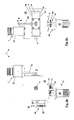
- FIGS. 1 to 12 Different embodiments of a magnetic motion converter 1 or a plurality of mutually coupled motion converters 1 for converting a linear movement into a rotational movement or a rotational movement into a linear movement and various embodiments of individual components of the magnetic motion converter 1 are shown in different views.
- the motion converter 1 comprises a magnet arrangement 2 with magnets which can be moved relative to one another, at least one first magnet 3 and a second magnet 4.
- the magnets 3, 4 each have at least one magnetically active side face formed as a magnet side face 5.
- Mutually assigned magnetic side surfaces 5 have a same magnetic polarity and limit in one, for example, in the FIGS. 1 to 5 Zero position shown by solid lines a plane non-curved magnetic gap 6, so that in the magnetic gap 6 here is a not further drawn magnetic field with repulsive forces prevails.
- the magnets 3,4 are already mentioned plastic bonded NdFeB magnets.
- the second magnet 4 is arranged pivotable about a pivot axis s, the pivot axis s extending in the plane of its magnet side surface 5.
- the second magnet 4 can in the in the FIGS. 1 to 10 shown embodiments of the motion converter 1 for converting a stroke b in a rotational movement by means of a stroke h generating drive 7 are pivoted back and forth.
- the Figures 11a and 11b shown embodiment of the motion converter 1 is designed to convert a rotary motion into a pivoting movement, which can be removed as a stroke b.
- the stroke h and the magnetic gap 6 are dimensioned such that the second magnet 4 does not strike directly against a component of the motion converter 1 via its pivoting movement.
- the second magnet 4 is in all embodiments a flat circular cylinder, whose at least one end face forms the magnet side surface 5.
- the first magnet 3 is designed as a part-cylindrical hub 8, whose at least one large side surface is designed as a magnet side surface 5.
- Possible embodiments of the turntable 8 as a circular turntable 8 or as a circular sector-like, circular segment-like and / or circular sector-like turntable 8 are described below.
- the turntable 8 is rotatably mounted about an axis of rotation d perpendicular to the magnet side surface 5 and perpendicular to the pivot axis s.
- Rotary axis d and pivot axis s intersect vertically.
- the magnet side surface 5 of the first magnet 3 rotatably mounted here has, with respect to its extent over the magnetic gap 6, a region 9 eccentric with respect to the axis of rotation d with a recess 10 and / or with a magnetization 11 which is weaker than that outside the eccentric region Range is 9.
- the first magnet 3 is also designed as a ring magnet and is in accordance with the embodiments Figures 1 and 2 as a hub 8 rotatably mounted centrally on the axis of rotation d. In the other embodiments of the motion converter, the axis of rotation d is rotatably guided centrally through the first magnet 3.
- FIG. 1 a particularly simple embodiment of the motion converter 1 with a rotatably mounted first magnet 3 and a pivotally mounted magnet 4 is shown.
- Both magnets 3, 4 have a circular cylindrical shape with magnetic side surfaces 5 at their end faces, wherein the first magnet 3, as in a plan according to FIG. 5 shown, a recess 10 which geometrically complements the here laterally truncated circular cylindrical shape of the first magnet 3 to the entire circular shape of the first magnet 3 indicated here by dashed lines.
- the second magnet 4 is in FIG. 1 as well as in the following FIGS. 2 to 4 in addition to his designated by solid lines rest position also shown in one of the indicated by a dotted line pivoting position and in a direction indicated by dashed lines second pivoting position.
- Both Verschwenkpositionen are maximum positions in which it is ensured that the second magnet 4 is only so far pivoted against the first magnet 3, that a sufficient slip between the magnets 3, 4 is ensured.
- the magnets 3, 4 are arranged with their magnetic side surfaces 5 parallel to each other.
- the driving stroke b can be reversed very shortly before reaching the position shown by dashed lines of the first magnet 3, whereby the second magnet pivoted in the direction of its second pivot position, corresponding to the magnetic field to the right of the axis of rotation d compressed and is inhomogeneous and a further angular momentum is generated on the first magnet 3. If the first magnet 3 and the second magnet 4 are moved at maximum relative to one another, then a maximum angular momentum acts on the first magnet 3. If they are pivoted maximally from one another, the angular momentum equals zero.
- FIG. 2 a second embodiment of the motion converter 1 is shown.
- the magnet assembly 2 in this case has two first magnets 3 and a second magnet 4, wherein the two first magnets 3 are arranged on both sides of the second magnet 4 and in the rest position with the second magnet 4 each define a flat, non-curved magnetic gap 6.
- the two first magnets 3 are arranged rotated by 180 ° with respect to the axis of rotation.
- an angular momentum can be exerted continuously on the first magnets 3 or on the axis of rotation d.
- the first magnets 3 are equal to the first magnet 3 according to FIG. 1 educated. This is also apparent from the plan view of the motion converter according to FIG. 2 clear. How further the FIG. 2 Removable, the second magnet 4 has a radial projection a with respect to the first magnet 3, to edge effects of the magnetic field in the magnetic gaps. 6 to reduce to the first magnet 3.
- the first magnet 3 is arranged statically and has the same shape as the second magnet 4.
- the second magnet 4 is, as in the previously described embodiments of the magnet assembly 2 about the pivot axis s in planar magnet side surfaces 5 back and forth pivotally mounted.
- magnetic gap 6, which is bounded by the two magnets 3, 4 designed as a hub 8 magnetic core element 14 is provided, which is arranged rotatably about the rotation axis d perpendicular to the magnetic side surface 5 of the first magnet 3.
- the magnetic core element 14 has with respect to its extension via the magnetic gap 6 a region 9 eccentric with respect to the rotation axis d with the recess 10 and / or with a permeability which is weaker than that outside the eccentric region 9.
- FIG. 3 is a simple embodiment of the motion converter 1 with a first magnet 3 and a second magnet 4, which are arranged in a zero position of the second magnet 4 with their magnetic side surfaces 5 parallel to each other and limit a flat, non-curved magnetic gap 6. Due to the same shapes of the two magnets 3, 4 and an intended same polarization and magnetization of their magnetic side surfaces 5 is formed in the magnetic gap 6, not shown here, symmetrical magnetic field, which is disturbed due to the eccentric portion 9 of the magnetic core element 14 in the magnetic gap 6.
- the magnetic core element 14 is at a dead center when it is in the region of the magnetic gap 6, in which the second magnet 4 is pivoted away from the maximum of the first magnet 3.
- the dead center can be overcome by the moment of inertia of the magnetic core element 14.
- FIG. 4 an embodiment of the motion converter 1 is shown, in which two first magnets 3 and a second magnet 4 pivotally mounted between the two first magnets 4 are provided, wherein the magnets 3, 4 define two magnetic gaps 6, in each of which a magnetic core element 14 is rotatably arranged.
- the two magnetic core elements 14 are also rotatably mounted on the rotational axis d and arranged offset by a rotation angle of 180 ° from each other.
- the special design of the hub 8 to that in the embodiments according to FIGS. 1 and 2 the first magnet 3 and in the embodiments of the FIGS. 3 and 4 the magnetic core element 14 are formed, crucial for the angular momentum, as this training an otherwise symmetrically designed magnetic field is disturbed.
- the eccentric portion 9 of the hub 8 may have a recess 10 and / or a magnetization 11 (first magnet 3) or a permeability (magnetic core element 14), which is different from the outside of the external region 9 and here in the presented embodiment of the motion converter 1 weaker than that outside the external area 9. This facts becomes quite schematic in FIG.
- FIG. 5a shown with a plan view of the hub 8, in which case the hub 8 in the eccentric regions 9 has a recess 10 and a weaker magnetization 11.
- the weaker magnetization 11 has not been separately identified.
- the recess 10 is so large that the turntable 8 is in fact designed as a semi-circular cylinder.
- Embodiments of the hub 8 are reproduced, which are asymmetrical with respect to an axis of symmetry perpendicular to the intended axis of rotation g.
- a corresponding asymmetrical torque can be exerted on the turntable 8, which brings the turntable 8 in a preferred direction of rotation r.
- the turntable 8 at one with respect to its intended direction of rotation r about the axis of rotation d rear side 15 in a direction of rotation r extending projection 16.
- the projection 16 is provided radially outward of the hub 8 to achieve maximum torque.
- the projection 16 is approximately uniformly wide over its radial extent.
- the projection 16 caused an "imbalance", which affects a synchronization of the turntable.
- a greater synchronization of the hub can, according to their training FIG. 5e be achieved.
- a cutting 18 is provided, wherein the projection 16 and cut 18 are offset by 180 degrees to each other. Through the cut 18, a correspondingly lower torque is generated counter to the direction of rotation r at this point, whereby the total torque in the direction of rotation r is amplified.
- All turntables according to the FIGS. 5a to e have in the center of a sleeve 19, by means of which the hub 8 rotatably on the axis of rotation d is fixed.
- the sleeve 19 is only in FIG. 5e illustrated groove , wherein it is provided that a correspondingly provided on the axis of rotation and not shown here spring engages in the installed position of the hub 8 in the groove 20.
- the drive 7 has a motor 21 which transmits the lifting movement b to a first section 4.1 of the second magnet 4 via a linkage 22.
- the second magnet 4 is designed here as an annular double magnet and mounted pivotably in a housing 23.
- the housing 23 is designed here for bundling and concentration of the magnetic field lines in the motion converter 1 here as a magnetic yoke.
- two concealed here by the housing 23 first magnets 3 are embedded and fixed in the housing 23.
- the two first magnets 3 and the second magnet 4 each delimit a magnetic gap 6, in each of which the magnetic core element 14 is arranged as a hub 8, wherein the hub 8 are mounted rotationally fixed on the rotation axis d.
- the axis of rotation d is mounted in the housing 23 and guided in the middle without contact by the annular second double magnet 4.
- the output side provided translation 13 has intermeshing gears 24, by means of which a here exemplified as a generator 25 trained output 12 is driven.
- a spring device 26 with a helical tension spring 27 is provided on the side opposite the pivot axis s to the linkage 22, wherein the helical tension spring 27 acts on a second section 4.2 on the second magnet 4 in a spring-effective manner.
- a pulse in the direction of the motor 21 away on the second magnet 4 is exerted on the linkage 22, whereby the helical tension spring 27 is deflected accordingly.
- FIGS. 7a and b To illustrate the arrangement of the turntables 8 and the magnetic core elements 14, the axis of rotation d is shown separately with the magnetic core elements 14 and the gear 24 provided on the output side.
- the two magnetic core elements 14 with respect to the rotation axis d offset by 180 degrees to each other.
- FIG. 7b shows a highly schematic plan view of the axis of rotation d with the magnetic core elements 14, wherein the magnetic core elements 14 are constructed approximately semicircular.
- FIG. 7c is a further embodiment of the axis of rotation d shown with the magnetic core elements 14 in a plan view, wherein the magnetic core elements 14 are slightly larger than semicircular and thereby overlap in the middle.
- the spring device 26 has two elongate leaf springs 30 which extend longitudinally on both sides perpendicular to the pivot axis s and the axis of rotation d and, according to FIG. 8 , attack with a first end portion 30.1 each at a second portion 4.2 of the second magnet 4, while they are resisted with a second end portion 30.2 in an abutment 31.
- the abutment 31 has in the embodiments according to the FIGS. 8 and 9 at least one pair of rollers 32 on that in the longitudinal axis the leaf spring 30 is longitudinally displaceable, whereby an effective spring length f of the leaf spring 30 and thus the spring force is adjustable.
- two pairs of rollers 32 are provided per leaf spring, which are independently displaceable in the longitudinal extension of the leaf spring 30.
- the respective rollers 33 of the roller pairs 32 are spaced apart so that the leaf spring 30 is movable between the roller pairs 32 with great play.
- FIG. 9 is an embodiment of the magnetic motion converter 1 shown in which two magnet assemblies 2 are arranged to each other that the two second magnets 4 of the two magnet assemblies 2 are interconnected via a common pivot axis s, while the magnetic core elements 14 are each arranged on a single axis of rotation d ,
- the above-described embodiments of the motion converter 1, according to which a plurality of, ie here two, turntables 8, are arranged on a common axis of rotation d, which are driven jointly by a single second magnet 4 can be referred to as a series connection of turntables 8.
- the arrangement of the magnet arrangements 2 in the embodiment according to FIG. 9 be referred to as parallel connection of axes of rotation d.
- the spring device 26 acts via the two leaf springs 30 for both magnet assemblies 2 directly on the pivot axis s, which also represents a structural simplification of a motion converter 1 with a plurality of "parallel" magnet assemblies 2.
- Conceivable but not further explained here, is a multiplicity of magnet arrangements which are arranged correspondingly parallel to one another.
- the leaf springs 30 in their second end region 30.2 each have a plate-shaped first magnetic element 34 with two side faces 5 designed as large side surfaces.
- a second magnetic element 35 Spaced to the magnet side surfaces 5 of the first magnetic elements 2 are each a second magnetic element 35 is provided which has a magnetic element facing the first magnetic side surface 5 of the same magnetic polarity as that of the magnetic side surface 5 of the first magnetic element 34.
- the magnetic elements 34, 35 arranged on a dashed line in this circumferential circle to the pivot axis 5 to each other so that their magnetic side surfaces 5 are guided in parallel over the pivoting of the second magnet 4 against each other.
- the leaf springs 30 have a very high rigidity, so that with pivoting of the second magnet 4 no appreciable deflection of the leaf spring 30 takes place.
- the second magnet 4 was pivoted via the drive 7 and thereby produced a rotary movement of the first magnet 3 or as a magnetic core element 14 formed turntable 8.
- FIG. 11 an embodiment of the same reproduced in which a rotational movement of the hub 8 can be converted into a pivoting movement of the second magnet 4.
- the axis of rotation d is rotated by a drive, not shown here, whereby, as a result of the previously described magnet assembly 2, the second magnet 4 is set in a pivoting movement.
- This pivoting movement of the second magnet 4 can via a Linkage 36, which acts eccentrically on a rocker plate 37, be converted back into a rotational movement b.
- FIG. 12 shows a perspective side view with a plurality of mutually coupled motion transducers 1. These are driven in this embodiment by a drive 7, are arranged on a common pivot axis s and each act on an associated axis of rotation d. Thus, they are arranged in this configuration on the output side parallel to each other. It can be done a distribution of the injected by the drive 7 kinetic energy to the axes of rotation d. At the same time, torques can be transmitted on several axes of rotation.
- the arrangements, which is not shown here can be linked in series with respect to the axis of rotation so that they act on a common axis of rotation d. Thus, a torque acting on the rotation axis d can be amplified.
- the individual motion transducers can act correspondingly phase-shifted on the rotary shaft, so that a greater smoothness can be achieved.
Landscapes
- Engineering & Computer Science (AREA)
- Power Engineering (AREA)
- Transmission Devices (AREA)
- Reciprocating, Oscillating Or Vibrating Motors (AREA)
Applications Claiming Priority (1)
| Application Number | Priority Date | Filing Date | Title |
|---|---|---|---|
| DE200810022584 DE102008022584A1 (de) | 2008-05-07 | 2008-05-07 | Magnetischer Bewegungswandler |
Publications (3)
| Publication Number | Publication Date |
|---|---|
| EP2117100A2 true EP2117100A2 (fr) | 2009-11-11 |
| EP2117100A3 EP2117100A3 (fr) | 2012-01-18 |
| EP2117100B1 EP2117100B1 (fr) | 2015-02-18 |
Family
ID=40668570
Family Applications (1)
| Application Number | Title | Priority Date | Filing Date |
|---|---|---|---|
| EP20090159544 Active EP2117100B1 (fr) | 2008-05-07 | 2009-05-06 | Convertisseur de mouvements magnétiques |
Country Status (2)
| Country | Link |
|---|---|
| EP (1) | EP2117100B1 (fr) |
| DE (1) | DE102008022584A1 (fr) |
Cited By (1)
| Publication number | Priority date | Publication date | Assignee | Title |
|---|---|---|---|---|
| IT201900011172A1 (it) * | 2019-07-08 | 2021-01-08 | Fabrizio Toni | Rotore magnetico |
Families Citing this family (1)
| Publication number | Priority date | Publication date | Assignee | Title |
|---|---|---|---|---|
| DE102021111366A1 (de) | 2021-05-03 | 2022-11-03 | Technische Universität Chemnitz - Körperschaft des öffentlichen Rechts | Vorrichtung zur Erzeugung elektrischer Energie in einem Energiewandler |
Citations (3)
| Publication number | Priority date | Publication date | Assignee | Title |
|---|---|---|---|---|
| US6433452B1 (en) | 2001-05-07 | 2002-08-13 | W. Ralph Graham | Magnetic motor |
| US6700248B2 (en) | 2001-05-09 | 2004-03-02 | Harmonic Drive, Inc. | Non-linear magnetic motion converter |
| US20070120432A1 (en) | 2005-11-25 | 2007-05-31 | Vaden David R | Axial magnetic cam |
Family Cites Families (3)
| Publication number | Priority date | Publication date | Assignee | Title |
|---|---|---|---|---|
| FR2233738A1 (en) * | 1973-06-14 | 1975-01-10 | Epee Et Cie Frederic L | Oscillatory to stepped rotational movement conversion - rotation from balance wheel magnetically coupled to second axle |
| US3967146A (en) * | 1974-04-24 | 1976-06-29 | Howard Gerald T | Magnetic motion conversion device |
| US4196365A (en) * | 1978-07-03 | 1980-04-01 | Doy Presley | Magnetic motor having rotating and reciprocating permanent magnets |
-
2008
- 2008-05-07 DE DE200810022584 patent/DE102008022584A1/de not_active Withdrawn
-
2009
- 2009-05-06 EP EP20090159544 patent/EP2117100B1/fr active Active
Patent Citations (3)
| Publication number | Priority date | Publication date | Assignee | Title |
|---|---|---|---|---|
| US6433452B1 (en) | 2001-05-07 | 2002-08-13 | W. Ralph Graham | Magnetic motor |
| US6700248B2 (en) | 2001-05-09 | 2004-03-02 | Harmonic Drive, Inc. | Non-linear magnetic motion converter |
| US20070120432A1 (en) | 2005-11-25 | 2007-05-31 | Vaden David R | Axial magnetic cam |
Cited By (1)
| Publication number | Priority date | Publication date | Assignee | Title |
|---|---|---|---|---|
| IT201900011172A1 (it) * | 2019-07-08 | 2021-01-08 | Fabrizio Toni | Rotore magnetico |
Also Published As
| Publication number | Publication date |
|---|---|
| EP2117100A3 (fr) | 2012-01-18 |
| EP2117100B1 (fr) | 2015-02-18 |
| DE102008022584A1 (de) | 2009-11-19 |
Similar Documents
| Publication | Publication Date | Title |
|---|---|---|
| DE2906335C2 (de) | Hin- und hergehende Linearbewegungseinrichtung | |
| EP2201663B1 (fr) | Rotor pour moteur électrique | |
| DE102014116659B4 (de) | Exzenterwelle mit festem und beweglichem Exzentergewicht | |
| DE69406876T2 (de) | Elektrischer Motor mit Vibrationselementen und elastischer Kupplung | |
| EP1131540A1 (fr) | Systeme d'entrainement electromagnetique | |
| DE102009021540A1 (de) | Transversalflussmotor als Außenläufermotor und Antriebsverfahren | |
| EP3084170A1 (fr) | Moteur à piston alternatif | |
| EP2973980B1 (fr) | Dispositif pour moteur à ultrasons | |
| EP0450288A2 (fr) | Moteur électrique linéaire | |
| DE69511902T2 (de) | Maschine mit drei-lappigen nocken | |
| DE102009053727A1 (de) | Zykloidgetriebe | |
| DE10211588B4 (de) | Linearmotor | |
| EP1438754A2 (fr) | Entrainement piezo-electrique | |
| EP2117100B1 (fr) | Convertisseur de mouvements magnétiques | |
| DE102011084425A1 (de) | Rotorblechpaket, Rotor und Verfahren zur Herstellung eines Rotorblechpakets | |
| DE102006016044A1 (de) | Getriebeeinheit und Werkzeughalter mit einer derartigen Getriebeeinheit | |
| DE60308140T2 (de) | Magnetische schlagvorrichtung und verfahren zur magnetischen erzeugung von schlagbewegung | |
| DE19955054A1 (de) | Elektromagnetischer Antrieb | |
| DE3786392T2 (de) | Elektromagnetische antriebsvorrichtung. | |
| DE19955067A1 (de) | Elektromagnetischer Aktuator | |
| DE102004037360B4 (de) | Elektromagnetischer Stellantrieb | |
| DE102010031107B4 (de) | Umformpresse mit einem Stößeldirektantrieb | |
| AT523723B1 (de) | Getriebemotor | |
| EP1869756B1 (fr) | Actionneur lineaire | |
| EP1732088B1 (fr) | Actionneur électromagnétique |
Legal Events
| Date | Code | Title | Description |
|---|---|---|---|
| PUAI | Public reference made under article 153(3) epc to a published international application that has entered the european phase |
Free format text: ORIGINAL CODE: 0009012 |
|
| AK | Designated contracting states |
Kind code of ref document: A2 Designated state(s): AT BE BG CH CY CZ DE DK EE ES FI FR GB GR HR HU IE IS IT LI LT LU LV MC MK MT NL NO PL PT RO SE SI SK TR |
|
| PUAL | Search report despatched |
Free format text: ORIGINAL CODE: 0009013 |
|
| AK | Designated contracting states |
Kind code of ref document: A3 Designated state(s): AT BE BG CH CY CZ DE DK EE ES FI FR GB GR HR HU IE IS IT LI LT LU LV MC MK MT NL NO PL PT RO SE SI SK TR |
|
| AX | Request for extension of the european patent |
Extension state: AL BA RS |
|
| RIC1 | Information provided on ipc code assigned before grant |
Ipc: H02K 49/10 20060101ALI20111212BHEP Ipc: H02K 7/06 20060101AFI20111212BHEP |
|
| 17P | Request for examination filed |
Effective date: 20120718 |
|
| 17Q | First examination report despatched |
Effective date: 20120918 |
|
| GRAP | Despatch of communication of intention to grant a patent |
Free format text: ORIGINAL CODE: EPIDOSNIGR1 |
|
| INTG | Intention to grant announced |
Effective date: 20140904 |
|
| RIN1 | Information on inventor provided before grant (corrected) |
Inventor name: MIHALJI, LAJOS |
|
| GRAS | Grant fee paid |
Free format text: ORIGINAL CODE: EPIDOSNIGR3 |
|
| GRAA | (expected) grant |
Free format text: ORIGINAL CODE: 0009210 |
|
| AK | Designated contracting states |
Kind code of ref document: B1 Designated state(s): AT BE BG CH CY CZ DE DK EE ES FI FR GB GR HR HU IE IS IT LI LT LU LV MC MK MT NL NO PL PT RO SE SI SK TR |
|
| REG | Reference to a national code |
Ref country code: GB Ref legal event code: FG4D Free format text: NOT ENGLISH |
|
| REG | Reference to a national code |
Ref country code: CH Ref legal event code: EP |
|
| REG | Reference to a national code |
Ref country code: AT Ref legal event code: REF Ref document number: 711003 Country of ref document: AT Kind code of ref document: T Effective date: 20150315 |
|
| REG | Reference to a national code |
Ref country code: IE Ref legal event code: FG4D Free format text: LANGUAGE OF EP DOCUMENT: GERMAN |
|
| REG | Reference to a national code |
Ref country code: DE Ref legal event code: R096 Ref document number: 502009010609 Country of ref document: DE Effective date: 20150402 |
|
| REG | Reference to a national code |
Ref country code: NL Ref legal event code: VDEP Effective date: 20150218 |
|
| REG | Reference to a national code |
Ref country code: LT Ref legal event code: MG4D |
|
| PG25 | Lapsed in a contracting state [announced via postgrant information from national office to epo] |
Ref country code: ES Free format text: LAPSE BECAUSE OF FAILURE TO SUBMIT A TRANSLATION OF THE DESCRIPTION OR TO PAY THE FEE WITHIN THE PRESCRIBED TIME-LIMIT Effective date: 20150218 Ref country code: FI Free format text: LAPSE BECAUSE OF FAILURE TO SUBMIT A TRANSLATION OF THE DESCRIPTION OR TO PAY THE FEE WITHIN THE PRESCRIBED TIME-LIMIT Effective date: 20150218 Ref country code: NO Free format text: LAPSE BECAUSE OF FAILURE TO SUBMIT A TRANSLATION OF THE DESCRIPTION OR TO PAY THE FEE WITHIN THE PRESCRIBED TIME-LIMIT Effective date: 20150518 Ref country code: LT Free format text: LAPSE BECAUSE OF FAILURE TO SUBMIT A TRANSLATION OF THE DESCRIPTION OR TO PAY THE FEE WITHIN THE PRESCRIBED TIME-LIMIT Effective date: 20150218 Ref country code: HR Free format text: LAPSE BECAUSE OF FAILURE TO SUBMIT A TRANSLATION OF THE DESCRIPTION OR TO PAY THE FEE WITHIN THE PRESCRIBED TIME-LIMIT Effective date: 20150218 Ref country code: SE Free format text: LAPSE BECAUSE OF FAILURE TO SUBMIT A TRANSLATION OF THE DESCRIPTION OR TO PAY THE FEE WITHIN THE PRESCRIBED TIME-LIMIT Effective date: 20150218 |
|
| PG25 | Lapsed in a contracting state [announced via postgrant information from national office to epo] |
Ref country code: IS Free format text: LAPSE BECAUSE OF FAILURE TO SUBMIT A TRANSLATION OF THE DESCRIPTION OR TO PAY THE FEE WITHIN THE PRESCRIBED TIME-LIMIT Effective date: 20150618 Ref country code: LV Free format text: LAPSE BECAUSE OF FAILURE TO SUBMIT A TRANSLATION OF THE DESCRIPTION OR TO PAY THE FEE WITHIN THE PRESCRIBED TIME-LIMIT Effective date: 20150218 Ref country code: NL Free format text: LAPSE BECAUSE OF FAILURE TO SUBMIT A TRANSLATION OF THE DESCRIPTION OR TO PAY THE FEE WITHIN THE PRESCRIBED TIME-LIMIT Effective date: 20150218 Ref country code: GR Free format text: LAPSE BECAUSE OF FAILURE TO SUBMIT A TRANSLATION OF THE DESCRIPTION OR TO PAY THE FEE WITHIN THE PRESCRIBED TIME-LIMIT Effective date: 20150519 |
|
| PG25 | Lapsed in a contracting state [announced via postgrant information from national office to epo] |
Ref country code: SK Free format text: LAPSE BECAUSE OF FAILURE TO SUBMIT A TRANSLATION OF THE DESCRIPTION OR TO PAY THE FEE WITHIN THE PRESCRIBED TIME-LIMIT Effective date: 20150218 Ref country code: DK Free format text: LAPSE BECAUSE OF FAILURE TO SUBMIT A TRANSLATION OF THE DESCRIPTION OR TO PAY THE FEE WITHIN THE PRESCRIBED TIME-LIMIT Effective date: 20150218 Ref country code: CZ Free format text: LAPSE BECAUSE OF FAILURE TO SUBMIT A TRANSLATION OF THE DESCRIPTION OR TO PAY THE FEE WITHIN THE PRESCRIBED TIME-LIMIT Effective date: 20150218 Ref country code: RO Free format text: LAPSE BECAUSE OF FAILURE TO SUBMIT A TRANSLATION OF THE DESCRIPTION OR TO PAY THE FEE WITHIN THE PRESCRIBED TIME-LIMIT Effective date: 20150218 Ref country code: EE Free format text: LAPSE BECAUSE OF FAILURE TO SUBMIT A TRANSLATION OF THE DESCRIPTION OR TO PAY THE FEE WITHIN THE PRESCRIBED TIME-LIMIT Effective date: 20150218 |
|
| REG | Reference to a national code |
Ref country code: DE Ref legal event code: R097 Ref document number: 502009010609 Country of ref document: DE |
|
| PG25 | Lapsed in a contracting state [announced via postgrant information from national office to epo] |
Ref country code: PL Free format text: LAPSE BECAUSE OF FAILURE TO SUBMIT A TRANSLATION OF THE DESCRIPTION OR TO PAY THE FEE WITHIN THE PRESCRIBED TIME-LIMIT Effective date: 20150218 |
|
| PLBE | No opposition filed within time limit |
Free format text: ORIGINAL CODE: 0009261 |
|
| STAA | Information on the status of an ep patent application or granted ep patent |
Free format text: STATUS: NO OPPOSITION FILED WITHIN TIME LIMIT |
|
| PG25 | Lapsed in a contracting state [announced via postgrant information from national office to epo] |
Ref country code: IT Free format text: LAPSE BECAUSE OF FAILURE TO SUBMIT A TRANSLATION OF THE DESCRIPTION OR TO PAY THE FEE WITHIN THE PRESCRIBED TIME-LIMIT Effective date: 20150218 |
|
| REG | Reference to a national code |
Ref country code: CH Ref legal event code: PL |
|
| 26N | No opposition filed |
Effective date: 20151119 |
|
| GBPC | Gb: european patent ceased through non-payment of renewal fee |
Effective date: 20150518 |
|
| PG25 | Lapsed in a contracting state [announced via postgrant information from national office to epo] |
Ref country code: MC Free format text: LAPSE BECAUSE OF FAILURE TO SUBMIT A TRANSLATION OF THE DESCRIPTION OR TO PAY THE FEE WITHIN THE PRESCRIBED TIME-LIMIT Effective date: 20150218 Ref country code: LI Free format text: LAPSE BECAUSE OF NON-PAYMENT OF DUE FEES Effective date: 20150531 Ref country code: LU Free format text: LAPSE BECAUSE OF FAILURE TO SUBMIT A TRANSLATION OF THE DESCRIPTION OR TO PAY THE FEE WITHIN THE PRESCRIBED TIME-LIMIT Effective date: 20150506 Ref country code: CH Free format text: LAPSE BECAUSE OF NON-PAYMENT OF DUE FEES Effective date: 20150531 |
|
| REG | Reference to a national code |
Ref country code: IE Ref legal event code: MM4A |
|
| REG | Reference to a national code |
Ref country code: FR Ref legal event code: ST Effective date: 20160129 |
|
| PG25 | Lapsed in a contracting state [announced via postgrant information from national office to epo] |
Ref country code: SI Free format text: LAPSE BECAUSE OF FAILURE TO SUBMIT A TRANSLATION OF THE DESCRIPTION OR TO PAY THE FEE WITHIN THE PRESCRIBED TIME-LIMIT Effective date: 20150218 |
|
| PG25 | Lapsed in a contracting state [announced via postgrant information from national office to epo] |
Ref country code: GB Free format text: LAPSE BECAUSE OF NON-PAYMENT OF DUE FEES Effective date: 20150518 Ref country code: IE Free format text: LAPSE BECAUSE OF NON-PAYMENT OF DUE FEES Effective date: 20150506 |
|
| PG25 | Lapsed in a contracting state [announced via postgrant information from national office to epo] |
Ref country code: FR Free format text: LAPSE BECAUSE OF NON-PAYMENT OF DUE FEES Effective date: 20150601 |
|
| REG | Reference to a national code |
Ref country code: AT Ref legal event code: MM01 Ref document number: 711003 Country of ref document: AT Kind code of ref document: T Effective date: 20150506 |
|
| PG25 | Lapsed in a contracting state [announced via postgrant information from national office to epo] |
Ref country code: AT Free format text: LAPSE BECAUSE OF NON-PAYMENT OF DUE FEES Effective date: 20150506 |
|
| PG25 | Lapsed in a contracting state [announced via postgrant information from national office to epo] |
Ref country code: MT Free format text: LAPSE BECAUSE OF FAILURE TO SUBMIT A TRANSLATION OF THE DESCRIPTION OR TO PAY THE FEE WITHIN THE PRESCRIBED TIME-LIMIT Effective date: 20150218 |
|
| PG25 | Lapsed in a contracting state [announced via postgrant information from national office to epo] |
Ref country code: BG Free format text: LAPSE BECAUSE OF FAILURE TO SUBMIT A TRANSLATION OF THE DESCRIPTION OR TO PAY THE FEE WITHIN THE PRESCRIBED TIME-LIMIT Effective date: 20150218 Ref country code: HU Free format text: LAPSE BECAUSE OF FAILURE TO SUBMIT A TRANSLATION OF THE DESCRIPTION OR TO PAY THE FEE WITHIN THE PRESCRIBED TIME-LIMIT; INVALID AB INITIO Effective date: 20090506 |
|
| PG25 | Lapsed in a contracting state [announced via postgrant information from national office to epo] |
Ref country code: CY Free format text: LAPSE BECAUSE OF FAILURE TO SUBMIT A TRANSLATION OF THE DESCRIPTION OR TO PAY THE FEE WITHIN THE PRESCRIBED TIME-LIMIT Effective date: 20150218 |
|
| PG25 | Lapsed in a contracting state [announced via postgrant information from national office to epo] |
Ref country code: BE Free format text: LAPSE BECAUSE OF NON-PAYMENT OF DUE FEES Effective date: 20150531 Ref country code: PT Free format text: LAPSE BECAUSE OF FAILURE TO SUBMIT A TRANSLATION OF THE DESCRIPTION OR TO PAY THE FEE WITHIN THE PRESCRIBED TIME-LIMIT Effective date: 20150618 |
|
| PG25 | Lapsed in a contracting state [announced via postgrant information from national office to epo] |
Ref country code: TR Free format text: LAPSE BECAUSE OF FAILURE TO SUBMIT A TRANSLATION OF THE DESCRIPTION OR TO PAY THE FEE WITHIN THE PRESCRIBED TIME-LIMIT Effective date: 20150218 |
|
| PG25 | Lapsed in a contracting state [announced via postgrant information from national office to epo] |
Ref country code: MK Free format text: LAPSE BECAUSE OF FAILURE TO SUBMIT A TRANSLATION OF THE DESCRIPTION OR TO PAY THE FEE WITHIN THE PRESCRIBED TIME-LIMIT Effective date: 20150218 |
|
| REG | Reference to a national code |
Ref country code: DE Ref legal event code: R082 Ref document number: 502009010609 Country of ref document: DE Representative=s name: LIPPERT STACHOW PATENTANWAELTE RECHTSANWAELTE , DE Ref country code: DE Ref legal event code: R081 Ref document number: 502009010609 Country of ref document: DE Owner name: MIHALJI, LAJOS, DE Free format text: FORMER OWNER: MIHALJI, LAJOS, 51789 LINDLAR, DE |
|
| PGFP | Annual fee paid to national office [announced via postgrant information from national office to epo] |
Ref country code: DE Payment date: 20250728 Year of fee payment: 17 |