EP2117193A2 - Architecture de transmission de transmetteur - Google Patents
Architecture de transmission de transmetteur Download PDFInfo
- Publication number
- EP2117193A2 EP2117193A2 EP08252363A EP08252363A EP2117193A2 EP 2117193 A2 EP2117193 A2 EP 2117193A2 EP 08252363 A EP08252363 A EP 08252363A EP 08252363 A EP08252363 A EP 08252363A EP 2117193 A2 EP2117193 A2 EP 2117193A2
- Authority
- EP
- European Patent Office
- Prior art keywords
- scramble
- frequency domain
- symbol
- coupled
- selector
- Prior art date
- Legal status (The legal status is an assumption and is not a legal conclusion. Google has not performed a legal analysis and makes no representation as to the accuracy of the status listed.)
- Ceased
Links
- 230000005540 biological transmission Effects 0.000 title claims abstract description 41
- 238000003780 insertion Methods 0.000 claims abstract description 28
- 230000037431 insertion Effects 0.000 claims abstract description 28
- 230000009466 transformation Effects 0.000 claims description 6
- 238000012545 processing Methods 0.000 claims description 4
- 238000013507 mapping Methods 0.000 claims description 3
- 230000004044 response Effects 0.000 description 20
- 230000000694 effects Effects 0.000 description 12
- 238000005516 engineering process Methods 0.000 description 8
- 238000000034 method Methods 0.000 description 8
- 238000010586 diagram Methods 0.000 description 7
- 230000001427 coherent effect Effects 0.000 description 5
- 238000013461 design Methods 0.000 description 4
- 238000005562 fading Methods 0.000 description 4
- 230000006870 function Effects 0.000 description 4
- 230000008901 benefit Effects 0.000 description 3
- 238000004891 communication Methods 0.000 description 3
- 239000000969 carrier Substances 0.000 description 2
- 238000005094 computer simulation Methods 0.000 description 2
- 230000002708 enhancing effect Effects 0.000 description 2
- 230000001965 increasing effect Effects 0.000 description 2
- 238000012986 modification Methods 0.000 description 2
- 230000004048 modification Effects 0.000 description 2
- 101150069124 RAN1 gene Proteins 0.000 description 1
- 101100355633 Salmo salar ran gene Proteins 0.000 description 1
- 230000008859 change Effects 0.000 description 1
- 238000010276 construction Methods 0.000 description 1
- 125000004122 cyclic group Chemical group 0.000 description 1
- 230000001066 destructive effect Effects 0.000 description 1
- 230000008569 process Effects 0.000 description 1
- 230000009467 reduction Effects 0.000 description 1
Images




Classifications
-
- H—ELECTRICITY
- H04—ELECTRIC COMMUNICATION TECHNIQUE
- H04L—TRANSMISSION OF DIGITAL INFORMATION, e.g. TELEGRAPHIC COMMUNICATION
- H04L27/00—Modulated-carrier systems
- H04L27/26—Systems using multi-frequency codes
- H04L27/2601—Multicarrier modulation systems
- H04L27/2614—Peak power aspects
-
- H—ELECTRICITY
- H04—ELECTRIC COMMUNICATION TECHNIQUE
- H04L—TRANSMISSION OF DIGITAL INFORMATION, e.g. TELEGRAPHIC COMMUNICATION
- H04L27/00—Modulated-carrier systems
- H04L27/26—Systems using multi-frequency codes
Definitions
- the present invention generally relates to a transmitter, and more particularly, to a transmission architecture of a transmitter.
- a transmitter in a digital communication and broadcasting system transmits an information signal to a receiver through a channel in the form of electromagnetic waves.
- the received signal may be distorted. If there is a long time interval between the received multi-path signals, the delay spread may be enlarged. Meanwhile, the reciprocal value of the delay spread is approximate to a coherent bandwidth, and the channel frequency response thereof may cause a frequency-selective fading effect.
- GI guard interval
- the network construction of the OFDM system can be classified into multifrequency network (MFN) and single frequency network (SFN).
- MFN multifrequency network
- SFN single frequency network
- the SFN has the following three apparent advantages. First, the SFN merely requires a small power but provides many distribution points, and thus covering a wide range. Second, the SFN saves frequency resources, because the whole system only requires one frequency. Third, when a user moves within the coverage area, the receiver in operation need not change the frequency. Therefore, most of the systems employ the SFN architecture to completely use the allocated frequency bands.
- the OFDM systems adopting the SFN architecture include digital video broadcasting-terrestrial (DVB-T), digital video broadcasting-handheld (DVB-H), digital audio broadcasting (DAB), terrestrial digital multimedia television broadcasting (DMB-T), and multimedia forward link only (FLO).
- the OFDM system further has the functions of channel encoding and signal interleaving, such that the consecutive errors caused by the channel effect during the transmission process can be eliminated, and when receiving signals, the error bits are corrected with correct ones based on the channel decoding and signal de-interleaving technology.
- the channel frequency response must be diversified, such that when the signal received by the receiver becomes an error signal after passing through a part of the channels with relatively poor frequency response, the error signal can be corrected according to a correct signal generated through a part of the channels with desirable frequency response.
- the transmitter in the OFDM system is usually accomplished by a diversity transmission technique or the receiver is accomplished by a diversity receiving technique.
- the diversity gain generated by the diversity technology may enhance the receiving performance of the receiver.
- the receiver may simultaneously receive identical transmitted signals from the two areas.
- the coherent bandwidth is a wideband coherent bandwidth having rather slow changes in the channel frequency response, so as to generate a flat fading channel response.
- the channel frequency responses on the boundary of the signal coverage areas of the two adjacent transmitters in the SFN make the signals have inverted phases, destructive interference may occur to the whole channel frequency responses, and channel frequency responses may have a rather low energy.
- the OFDM transmission technology may not show its advantage in counteracting the multi-path channel effect.
- the OFDM transmission technology has the functions of channel encoding and signal interleaving, it still cannot correct the error signal generated by the poor channel frequency response with the correct ones generated by the desirable channel frequency response under the circumstances that the channel frequency response has a too low energy and the fading coherent time is extremely long. Therefore, it has become a key point in the design of a transmitter as to how to process signals in the transmitter with diversity technology without affecting the original system performance of the SFN or altering the original design of the receiver.
- the transmitted signals may have excessive large peak-to-average power ratios (PAPRs).
- PAPRs peak-to-average power ratios
- nonlinear distortion of signals may occur when being transmitted through a power amplifier, that is, some transmitted signals with relatively large power may be clipped. Therefore, it is also a key point in the design of the transmitter as to how to reduce the PAPRs of the signals transmitted by the transmitter.
- each OFDM symbol ( X ) of a transmitted signal with a length of N samples is divided into M symbols ( X 1 , X 2 , ..., X M ). In each of the symbols, only an individual part of the sub-carriers are assigned with values, and the others are zero.
- Each of such symbols goes through inverse discrete Fourier transformation with a length of N points and then they are respectively multiplied by a set of coefficients (b 1 , b 2 , ..., b M ). Afterwards, these products are summed up to calculate a PAPR of the summed signal.
- a set of coefficients (b 1 , b 2 , ..., b M ).
- these products are summed up to calculate a PAPR of the summed signal.
- different sets of coefficients are used for producing different corresponding summed signals, so as to calculate a plurality of corresponding PAPRs, and then the set of coefficients corresponding to the minimum PAPR is determined. Finally, the set of coefficients and the corresponding summed signal are output. Additionally, as the set of coefficients are designed as random coefficients, they may cause difficulties in the channel estimation of the receiver if being combined with the channel effect.
- the known reference signal for example, a pilot signal
- the receiver needs a side information and a safer channel to transmit the side information.
- the side information is used for informing the receiver about the set of coefficients, so as to facilitate the receiver to restore the original OFDM symbol ( X ).
- the conventional transmitter has been improved by enhancing the multi-cell diversity gain, or by reducing the PAPR.
- a transmitter capable of both enhancing the multi-cell diversity gain and reducing the PAPR is required.
- the present invention is directed to a transmission architecture of a transmitter.
- the present invention provides a transmission architecture of a transmitter.
- An exemplary example of the above-mentioned transmission architecture of a transmitter consistent with the invention includes a forestage module, a pilot insertion, a scramble selector, and a backstage module.
- the forestage module is used for transmitting a frequency domain data symbol.
- the pilot insertion is coupled to the forestage module and used for receiving the frequency domain data symbol and inserting a pilot signal in the frequency domain data symbol to produce a frequency domain pilot symbol.
- the scramble selector is coupled to the pilot insertion and is used for generating a plurality of scramble patterns used to perform a scramble operation with the frequency domain pilot symbol, and then performing a select operation to produce a requirement symbol.
- the backstage module is coupled to the scramble selector and is used for processing and transmitting the requirement symbol out of the transmitter.
- a transmission architecture of a transmitter comprising a forestage module, for transmitting a frequency domain data symbol; a pilot insertion, coupled to the forestage module, for receiving the frequency domain data symbol, and inserting a pilot signal in the frequency domain data symbol to produce a frequency domain pilot symbol; a scramble selector, coupled to the pilot insertion, for generating a plurality of scramble patterns used to perform a scramble operation with the frequency domain pilot symbol, and then performing a select operation to produce a requirement symbol; and a backstage module, coupled to the scramble selector, for processing and transmitting the requirement symbol out of the transmitter.
- the pilot insertion first inserts a pilot signal in the frequency domain data symbol to generate a frequency domain pilot symbol and then transmits the frequency domain pilot symbol to the scramble selector.
- the channel frequency response estimated through using the pilot signal further includes the effect of the scramble patterns.
- FIG. 1 is a system block diagram of a transmission architecture of a transmitter according to an exemplary embodiment consistent with the present invention
- FIG. 2 is a circuit block diagram of a forestage module in FIG. 1 ;
- FIG. 3A is a circuit block diagram of a scramble selector in FIG. 1 ;
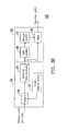
- FIG. 3B is a circuit block diagram of a scrambler and a selector in FIG. 3A ;
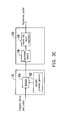
- FIG. 3C is another circuit block diagram of the scrambler and the selector in FIG. 3A ;
- FIG. 4 is a circuit block diagram of a backstage module in FIG. 1 ;
- FIG. 5 shows probability results of measured PAPRs of a transmitter according to two exemplary embodiments consistent of the present invention and that of a common transmitter of an OFDM system
- FIG. 6 shows block error rate results of measured signal-to-noise ratios of a transmitter according to two exemplary embodiments consistent of the present invention and that of a common transmitter of an OFDM system.
- an OFDM system of the SFN is taken as an application example for the present invention, and the transmission architecture of a transmitter provided by the present invention will be illustrated below through the embodiments of the present invention with reference to the accompanying drawings.
- FIG. 1 is a system block diagram of a transmission architecture of a transmitter 100 according to an exemplary embodiment consistent of the present invention.
- the transmission architecture includes a forestage module 110, a pilot insertion 120, a scramble selector 130, and a backstage module 140.
- the forestage module 110 further includes a data source bit stream generator 111, a channel encoder 112, an interleaver 113, and a mapper 114.
- the data source bit stream generator 111 generates a frequency domain data bit stream to be transmitted.
- the channel encoder 112 is coupled to the data source bit stream generator 111 and is used for receiving the frequency domain data bit stream provided by the data source bit stream generator 111, and performing channel encoding on the frequency domain data bit stream.
- the interleaver 113 is coupled to the channel encoder 112 and is used for receiving the encoded frequency domain data bit stream, and performing interleaving on the encoded frequency domain data bit stream.
- the mapper 114 is coupled to the interleaver 113 and is used for mapping the interleaved encoded frequency domain data bit stream into the frequency domain data symbol, and then transmitting the frequency domain data symbol to the pilot insertion 120.
- the mapper 114 may be a 16-stage quadrature amplitude modulator and may be used for performing a 16-stage quadrature amplitude modulation (16-QAM) mapping on the interleaved encoded frequency domain data bit stream to produce a frequency domain data symbol, and the 16-stage quadrature amplitude modulator may also be substituted by other mappers.
- the pilot insertion 120 is coupled to the forestage module 110 and is used for receiving the frequency domain data symbol transmitted by the forestage module 110, and inserting a pilot signal in the frequency domain data symbol to produce a frequency domain pilot symbol.
- the pilot signal for being inserted is a known reference signal for estimating a channel effect.
- the scramble selector 130 is coupled to the pilot insertion 120 and may include a scrambler 131 and a selector 132 ( Fig. 3A ).
- a plurality of scramble patterns generated in the scrambler 131 are used to perform a scramble operation with the frequency domain pilot symbol, and then a plurality of scramble symbols are produced and sent into a selector. Afterwards, a select operation is performed to produce a requirement symbol in the selector 132.
- the scramble operation performed between the scramble patterns and the frequency domain pilot symbol may be a multiply operation, or a combination of a multiply operation and an inverse fast Fourier transformation operation.
- the implementation of the scramble operation is not intended to limit the present invention.
- the condition for selecting the requirement symbol may be a time domain scramble symbol with a relative minimum PAPR, which is not intended to limit the present invention.
- the scramble selector 130 includes the scrambler 131 and the selector 132, as shown in FIG. 3A , and the operations of the scrambler 131 and the selector 132 may be obtained with reference to FIG. 3B .
- the scrambler 131 is coupled to the pilot insertion 120, and the selector 132 is coupled between the scrambler 131 and the backstage module 140.
- the scrambler 131 includes a scramble parameter generator 133, a multiplier 134, and an inverse fast Fourier transformer 135.
- the multiplier 134 multiplies the scramble patterns with the frequency domain pilot symbol to produce a plurality of frequency domain scramble symbols.
- the inverse fast Fourier transformer 135 is coupled to the multiplier 134 and is used for converting the frequency domain scramble symbols into the corresponding time domain scramble symbols.
- x ⁇ ′ j x n ⁇ ′ j
- x ' ( j ) is the j th time domain scramble symbol
- x n ' ( j ) is the n th sample in the j th time domain scramble symbol
- the selector 132 includes a PAPR calculator 136, a minimum selector 137, and a switch 138.
- the minimum selector 137 is coupled to the PAPR calculator 136 and is used for selecting a minimum PAPR from the output of the PAPR calculator 136, and informing the switch 138 about the index number of the scramble pattern corresponding to the minimum PAPR.
- the switch 138 selects one of the time domain scramble symbols to be transmitted to the backstage module 140.
- the switch 138 sets the time domain scramble symbol ( x '( j opt ) ) with the minimum PAPR stored in the register as the requirement symbol, and transmits the requirement symbol to the backstage module 140.
- the scrambler 131 generates a plurality of frequency domain scramble symbols to be output to the selector 132 after the multiplier 134 multiplies the scramble patterns generated by the scramble parameter generator 133 with the frequency domain pilot symbol.
- the selector 132 takes an optimal frequency domain scramble symbol selected from the plurality of frequency domain scramble symbols by the requirement selector 139 according to a particular rule as the frequency domain requirement symbol, and then, a requirement symbol is formed by the frequency domain requirement symbol through the inverse fast Fourier transformer 135, and meanwhile, the selector 132 outputs the requirement symbol to the backstage module 140.
- the principle for the particular rule is to select one frequency domain scramble symbol that is corresponding to a time domain scramble symbol with the minimum PAPR from the plurality of frequency domain scramble symbols.
- the implementation scheme of the particular rule is not intended to limit the scope of the present invention.
- the backstage module 140 is coupled to the scramble selector 130 and is used for receiving the requirement symbol.
- the backstage module includes a GI insertion 141 and an antenna unit 142.
- the GI insertion 141 is coupled between the selector 132 and the antenna unit 142 and is used for receiving the requirement symbol and inserting a guard interval (GI) by means of cyclic prefix in the requirement symbol.
- the antenna unit 142 is coupled to the GI insertion 141 and is used for transmitting the signals out of the transmitter 100 in the form of electromagnetic waves.
- the plurality of scramble patterns generated by the scramble selector 130 are irrelevant to each other in the transmitters of different cells in the SFN system, but the scramble parameters in each of the scramble patterns need not be completely irrelevant, which satisfies the scramble operation as long as there is a little randomness.
- the scramble selector 130 may generate the scramble patterns in a scramble mode of frequency domain or in a scramble mode of both the frequency domain and time domain, which is not intended to limit scope of the present invention.
- the plurality of scramble patterns generated by the scramble selector 130 added to the transmission architecture are irrelevant to each other in the transmitters of different cells in the SFN system, the multi-cell diversity gain may be increased.
- one time domain scramble symbol with a relative minimum PAPR is selected to reduce the PAPR of the transmitted signal.
- the PAPR may be reduced through the conventional partial transmit sequence (PTS) method.
- PTS partial transmit sequence
- the forestage module 110, the pilot insertion 120, the scramble selector 130, and the backstage module 140 may also be implemented through other means, for example, referring to the paper, entitled “ OFDM with Reduced Peak-to-average Power Ratio by Optimum Combination of Partial Transmit Sequences", (Electronics Letters, vol. 33, no. 5, pp. 368-369, Feb. 1997) issued by S.H. Muller and J.B. Huber .
- the transmission architecture of this embodiment may reduce the PAPR of the transmitted signal and enhance the multi-cell diversity gain.
- the SFN system has plenty of cells, in which each cell at least includes a transmitter and a receiver, and the transmitter employs the transmission architecture of this embodiment.
- the scramble patterns generated by the scramble selectors in different transmitters are irrelevant to each other, which is the key point for improving the multi-cell diversity gain of the present invention.
- this embodiment is further different from the conventional transmission architecture in that, the pilot insertion 120 first inserts a pilot signal in the frequency domain data symbol to produce the frequency domain pilot symbol and then transmits the frequency domain pilot symbol to the scramble selector 130. Therefore, when the OFDM receiver in the SFN system estimates a channel response, the channel frequency response estimated through using the pilot signal also includes the effect of the scramble patterns. Accordingly, as for the OFDM system in the SFN system, there is no need to provide a side information containing the scramble pattern information to the receiver. Therefore, as for the OFDM system in the SFN system, with a transmitter adopting the transmission architecture of the present invention, the original receiver need not be changed at all.
- FIG. 5 shows probability results of measured PAPRs of a transmitter according to two embodiments of the present invention and that of a common transmitter of an OFDM system.
- the horizontal axis indicates a given PAPR (dB)
- the longitudinal axis indicates probability value when the PAPRs obtained through computer simulation are larger than the given PAPR.
- the transmitter of Embodiment 1 adopts a scramble mode of frequency domain according to the present invention
- the transmitter of Embodiment 2 adopts a scramble mode of both the frequency domain and time domain according to the present invention
- the common transmitter of an OFDM system does not employ a scramble selector. As seen from FIG.
- the probability for the transmitters of Embodiment 1 and Embodiment 2 to have a PAPR larger than 9 dB (a given PAPR) is less than 0.1 %.
- the probability for the common transmitter of an OFDM system to have a PAPR larger than 9 dB (a given PAPR) is from 0.2 to 0.3, which is much higher than the probability of the transmitters of Embodiment 1 and Embodiment 2. Therefore, the present invention can reduce the PAPR of the transmitted signal.
- FIG. 6 shows block error rate results of measured signal-to-noise ratios of a transmitter according to two embodiments of the present invention and that of a common transmitter of an OFDM system.
- the horizontal axis indicates a given signal-to-noise power ratio (dB)
- the longitudinal axis indicates the block error rate measured by the receiver at an output end of a channel decoding module through computer simulation for a given signal-to-noise power ratio (the channel is a combined channel of two single-path channels).
- dB the value of the signal-to-noise power ratio that is needed when the block error rate reaches 1%.
- the transmitter of Embodiment 1 adopts a scramble mode of frequency domain according to the present invention
- the transmitter of Embodiment 2 adopts a scramble mode of both the frequency domain and time domain according to the present invention
- the common transmitter of an OFDM system does not employ a scramble selector.
- the block error rates of the transmitters of Embodiment 1 and Embodiment 2 reach 1%
- the required signal-to-noise ratio is only about 17.5 dB
- the block error rate of the common transmitter of an OFDM system reaches 1%
- the required signal-to-noise ratio rises to about 24 dB. Therefore, the present invention can increase the multi-cell diversity gain.
- the transmitter according to an embodiment of the present invention is suitable for being used in an OFDM system of the SFN system, for reducing the PAPRs of the transmitted signals and increasing the multi-cell diversity gain, and the original receiver does not need to be changed at all.
Landscapes
- Engineering & Computer Science (AREA)
- Computer Networks & Wireless Communication (AREA)
- Signal Processing (AREA)
- Radio Transmission System (AREA)
Applications Claiming Priority (1)
| Application Number | Priority Date | Filing Date | Title |
|---|---|---|---|
| TW097107500A TWI351823B (en) | 2008-03-04 | 2008-03-04 | Transmission architecture of transmitter |
Publications (2)
| Publication Number | Publication Date |
|---|---|
| EP2117193A2 true EP2117193A2 (fr) | 2009-11-11 |
| EP2117193A3 EP2117193A3 (fr) | 2012-01-18 |
Family
ID=40790854
Family Applications (1)
| Application Number | Title | Priority Date | Filing Date |
|---|---|---|---|
| EP08252363A Ceased EP2117193A3 (fr) | 2008-03-04 | 2008-07-10 | Architecture de transmission de transmetteur |
Country Status (3)
| Country | Link |
|---|---|
| US (1) | US8238507B2 (fr) |
| EP (1) | EP2117193A3 (fr) |
| TW (1) | TWI351823B (fr) |
Families Citing this family (7)
| Publication number | Priority date | Publication date | Assignee | Title |
|---|---|---|---|---|
| JP4447575B2 (ja) * | 2006-05-01 | 2010-04-07 | 株式会社エヌ・ティ・ティ・ドコモ | 送信装置及び送信方法 |
| US8787177B2 (en) * | 2008-11-03 | 2014-07-22 | Apple Inc. | Techniques for radio link problem and recovery detection in a wireless communication system |
| KR101011289B1 (ko) * | 2009-08-04 | 2011-01-28 | 성균관대학교산학협력단 | 수신 신호 복조 방법 및 이를 수행하는 장치 |
| WO2011112909A2 (fr) | 2010-03-12 | 2011-09-15 | Sunrise Micro Devices, Inc. | Communications peu consommatrices d'énergie |
| US9088888B2 (en) * | 2010-12-10 | 2015-07-21 | Mitsubishi Electric Research Laboratories, Inc. | Secure wireless communication using rate-adaptive codes |
| WO2013133746A2 (fr) * | 2012-03-06 | 2013-09-12 | Telefonaktiebolaget L M Ericsson (Publ) | Contrôleur de réseau radio, station de base serveuse, équipement d'utilisateur et procédés associés |
| CN111371718B (zh) * | 2018-12-26 | 2022-10-14 | 深圳市力合微电子股份有限公司 | 一种无线通信系统的非循环前导信号生成方法 |
Citations (3)
| Publication number | Priority date | Publication date | Assignee | Title |
|---|---|---|---|---|
| EP1679849A1 (fr) | 2005-01-11 | 2006-07-12 | Motorola, Inc. | Appareil et procédé de communication OFDM, dans lesquels les symboles pilotes sont pondérés de façon a réduire le rapport puissance de crête/puissance moyenne |
| EP1681822A2 (fr) | 2005-01-14 | 2006-07-19 | Fujitsu Ltd. | Contrôle du rapport puissance de crête - puissance moyenne dans les systèmes de communication sans fil |
| US20060184862A1 (en) | 2001-03-27 | 2006-08-17 | Kim Je-Woo | Orthogonal frequency division multiplexing/modulation communication system for improving ability of data transmission and method thereof |
Family Cites Families (11)
| Publication number | Priority date | Publication date | Assignee | Title |
|---|---|---|---|---|
| CA1331644C (fr) * | 1988-06-25 | 1994-08-23 | Yoshihiro Yamamura | Systeme de communication a brouillage utilisant des filtres transversaux adaptatifs pour le debrouillage des signaux recus |
| US5425050A (en) * | 1992-10-23 | 1995-06-13 | Massachusetts Institute Of Technology | Television transmission system using spread spectrum and orthogonal frequency-division multiplex |
| JP3722969B2 (ja) * | 1998-01-08 | 2005-11-30 | 株式会社東芝 | 再送制御方法及び再送制御装置 |
| US7020185B1 (en) * | 2000-11-28 | 2006-03-28 | Lucent Technologies Inc. | Method and apparatus for determining channel conditions in a communication system |
| JP3815344B2 (ja) | 2002-02-21 | 2006-08-30 | 株式会社日立製作所 | 多値変調に適した符号語マッピング方法 |
| US7280467B2 (en) | 2003-01-07 | 2007-10-09 | Qualcomm Incorporated | Pilot transmission schemes for wireless multi-carrier communication systems |
| ATE532304T1 (de) * | 2004-12-21 | 2011-11-15 | Ericsson Telefon Ab L M | Sendervorrichtung und verfahren zum senden von paketdateneinheiten in einem kommunikationssystem |
| CN101151832A (zh) * | 2005-03-30 | 2008-03-26 | 松下电器产业株式会社 | 通信终端装置、基站装置和接收方法 |
| JP4445474B2 (ja) | 2006-01-16 | 2010-04-07 | 株式会社東芝 | Ofdm信号の送信方法、ofdm送信機及びofdm受信機 |
| US7760587B2 (en) * | 2007-01-04 | 2010-07-20 | Ocean Acoustical Services and Instrumentation Systems (OASIS), Inc. | Methods of and systems for monitoring the acoustic transmission conditions in underwater areas using unmanned, mobile underwater vehicles |
| US8359041B2 (en) * | 2008-02-15 | 2013-01-22 | Futurewei Technologies, Inc. | System and method for adaptively controlling feedback information |
-
2008
- 2008-03-04 TW TW097107500A patent/TWI351823B/zh not_active IP Right Cessation
- 2008-06-03 US US12/131,930 patent/US8238507B2/en active Active
- 2008-07-10 EP EP08252363A patent/EP2117193A3/fr not_active Ceased
Patent Citations (3)
| Publication number | Priority date | Publication date | Assignee | Title |
|---|---|---|---|---|
| US20060184862A1 (en) | 2001-03-27 | 2006-08-17 | Kim Je-Woo | Orthogonal frequency division multiplexing/modulation communication system for improving ability of data transmission and method thereof |
| EP1679849A1 (fr) | 2005-01-11 | 2006-07-12 | Motorola, Inc. | Appareil et procédé de communication OFDM, dans lesquels les symboles pilotes sont pondérés de façon a réduire le rapport puissance de crête/puissance moyenne |
| EP1681822A2 (fr) | 2005-01-14 | 2006-07-19 | Fujitsu Ltd. | Contrôle du rapport puissance de crête - puissance moyenne dans les systèmes de communication sans fil |
Non-Patent Citations (3)
| Title |
|---|
| HEUNG-GYOON RYU ET AL: "Interleaving method without side information for the PAPR reduction of OFDM system", COMMUNICATIONS AND INFORMATION TECHNOLOGIES, 2007. ISCIT '07. INT ERNATIONAL SYMPOSIUM ON, IEEE, PI, 1 October 2007 (2007-10-01), pages 72 - 76, XP031166432, ISBN: 978-1-4244-0976-1, DOI: 10.1109/ISCIT.2007.4391987 * |
| KOJI AKITA ET AL: "Group-Wise Scrambling Diversity for Broadcast and Multicast Services in OFDM Cellular System", VEHICULAR TECHNOLOGY CONFERENCE, 2007. VTC-2007 FALL. 2007 IEEE 66TH, IEEE, PI, 1 September 2007 (2007-09-01), pages 174 - 178, XP031147389, ISBN: 978-1-4244-0263-2 * |
| SAITO M ET AL: "Peak-to-Average Power Ratio Reduction Method Suitable for MC-CDMA System Downlink", PERSONAL, INDOOR AND MOBILE RADIO COMMUNICATIONS, 2005. PIMRC 2005. IE EE 16TH INTERNATIONAL SYMPOSIUM ON BERLIN, GERMANY 11-14 SEPT. 2005, PISCATAWAY, NJ, USA,IEEE, vol. 1, 11 September 2005 (2005-09-11), pages 286 - 290, XP010926415, ISBN: 978-978-38007-2-4, DOI: 10.1109/PIMRC.2005.1651444 * |
Also Published As
| Publication number | Publication date |
|---|---|
| US8238507B2 (en) | 2012-08-07 |
| EP2117193A3 (fr) | 2012-01-18 |
| US20090225895A1 (en) | 2009-09-10 |
| TWI351823B (en) | 2011-11-01 |
| TW200939645A (en) | 2009-09-16 |
Similar Documents
| Publication | Publication Date | Title |
|---|---|---|
| KR100434473B1 (ko) | 직교주파수 분할 다중 시스템에서 채널 복호 장치 및 방법 | |
| CN105814856B (zh) | 控制组合波形的方法、设备和系统、组合多个信号的设备 | |
| US7376074B2 (en) | Apparatus and method for transmitting and receiving side information of a partial transmit sequence in an OFDM communication system | |
| US9723341B2 (en) | Apparatus for transmitting broadcast signals, apparatus for receiving broadcast signals, method for transmitting broadcast signals and method for receiving broadcast signals | |
| US8238507B2 (en) | Transmission architecture of transmitter | |
| KR101476869B1 (ko) | 부호화 직교 주파수 분할 멀티플렉싱을 위한 장치 및 방법 | |
| US8107356B2 (en) | Method and apparatus for transmitting/receiving a signal in an FFH-OFDM communication system | |
| US20070171994A1 (en) | Methods for data transmission | |
| Samo et al. | A performance study of DVB-T2 and DVB-T2-Lite for mobile reception | |
| KR20060059221A (ko) | 멀티캐리어 통신 시스템에서 피크대 평균 전력비 감소 장치및 방법 | |
| CN102960038B (zh) | 在单载波通信系统中的待发送信号 | |
| EP2905936B1 (fr) | Diffusion vidéo numérique - système de câbles et procédé permettant de traiter les fréquences réservées | |
| KR20070045343A (ko) | 송신 장치, 수신 장치, 통신 시스템 및 통신 방법 | |
| JP4932641B2 (ja) | 通信装置におけるピーク電力低減装置 | |
| EP1750387A1 (fr) | Procédé pour l'étalement bidimensionelle pour un système OFDM-CDM | |
| CN101316125A (zh) | 发射功率调整方法及系统 | |
| Elavarasan et al. | Peak-power reduction using improved partial transmit sequence in orthogonal frequency division multiplexing systems | |
| US9031159B2 (en) | Communication device and communication method | |
| CN101534175B (zh) | 发射机的传输系统 | |
| WO2004109953A1 (fr) | Procede et appareil pour systeme d'acces multiple par repartition de code a multiporteuse | |
| KR100637710B1 (ko) | 최대전력 대 평균전력비 및/또는 연산량 감소를 위한선택사상기법의 직교 주파수 분할 다중 반송파 통신 방법 | |
| EP2081311A1 (fr) | Dispositif de transmission et de réception radio à multiporteuse, système de communication radio à multiporteuse, procédé de transmission radio à multiporteuse et programme | |
| Elkamchouchi et al. | Efficient receiver design for frame based MC-CDMA in multipath Nakagami-m fading channels | |
| Huang et al. | Parallel packet transmission based on OFDM |
Legal Events
| Date | Code | Title | Description |
|---|---|---|---|
| PUAI | Public reference made under article 153(3) epc to a published international application that has entered the european phase |
Free format text: ORIGINAL CODE: 0009012 |
|
| AK | Designated contracting states |
Kind code of ref document: A2 Designated state(s): AT BE BG CH CY CZ DE DK EE ES FI FR GB GR HR HU IE IS IT LI LT LU LV MC MT NL NO PL PT RO SE SI SK TR |
|
| AX | Request for extension of the european patent |
Extension state: AL BA MK RS |
|
| PUAL | Search report despatched |
Free format text: ORIGINAL CODE: 0009013 |
|
| AK | Designated contracting states |
Kind code of ref document: A3 Designated state(s): AT BE BG CH CY CZ DE DK EE ES FI FR GB GR HR HU IE IS IT LI LT LU LV MC MT NL NO PL PT RO SE SI SK TR |
|
| AX | Request for extension of the european patent |
Extension state: AL BA MK RS |
|
| RIC1 | Information provided on ipc code assigned before grant |
Ipc: H04B 7/02 20060101ALI20111215BHEP Ipc: H04L 27/26 20060101AFI20111215BHEP |
|
| 17P | Request for examination filed |
Effective date: 20120329 |
|
| AKX | Designation fees paid |
Designated state(s): AT BE BG CH CY CZ DE DK EE ES FI FR GB GR HR HU IE IS IT LI LT LU LV MC MT NL NO PL PT RO SE SI SK TR |
|
| 17Q | First examination report despatched |
Effective date: 20131125 |
|
| RAP1 | Party data changed (applicant data changed or rights of an application transferred) |
Owner name: A-OPTRONICS CO., LTD. |
|
| RAP1 | Party data changed (applicant data changed or rights of an application transferred) |
Owner name: JIANGONG IP SERVICES LTD. |
|
| RAP1 | Party data changed (applicant data changed or rights of an application transferred) |
Owner name: FORESIGHT IP SERVICES INC. |
|
| RAP1 | Party data changed (applicant data changed or rights of an application transferred) |
Owner name: NANJING TRIDUCTOR NETWORK TECHNOLOGY CO., LTD. |
|
| STAA | Information on the status of an ep patent application or granted ep patent |
Free format text: STATUS: THE APPLICATION HAS BEEN REFUSED |
|
| 18R | Application refused |
Effective date: 20160303 |