EP2117281B1 - Kochfeld mit einer Kochfeldplatte sowie Verfahren zur Steuerung eines Kochprozesses - Google Patents
Kochfeld mit einer Kochfeldplatte sowie Verfahren zur Steuerung eines Kochprozesses Download PDFInfo
- Publication number
- EP2117281B1 EP2117281B1 EP09006109A EP09006109A EP2117281B1 EP 2117281 B1 EP2117281 B1 EP 2117281B1 EP 09006109 A EP09006109 A EP 09006109A EP 09006109 A EP09006109 A EP 09006109A EP 2117281 B1 EP2117281 B1 EP 2117281B1
- Authority
- EP
- European Patent Office
- Prior art keywords
- sensor unit
- hob
- cooking
- heat
- heating device
- Prior art date
- Legal status (The legal status is an assumption and is not a legal conclusion. Google has not performed a legal analysis and makes no representation as to the accuracy of the status listed.)
- Not-in-force
Links
- 238000010411 cooking Methods 0.000 title claims abstract description 33
- 238000000034 method Methods 0.000 title claims abstract description 23
- 238000010438 heat treatment Methods 0.000 claims description 24
- 230000001276 controlling effect Effects 0.000 claims description 8
- 230000006698 induction Effects 0.000 claims description 5
- 230000001105 regulatory effect Effects 0.000 claims description 3
- 239000006112 glass ceramic composition Substances 0.000 claims 2
- 239000002241 glass-ceramic Substances 0.000 abstract description 14
- 238000005259 measurement Methods 0.000 description 4
- 230000005855 radiation Effects 0.000 description 4
- 238000011109 contamination Methods 0.000 description 2
- 230000005540 biological transmission Effects 0.000 description 1
- 238000009529 body temperature measurement Methods 0.000 description 1
- 230000001419 dependent effect Effects 0.000 description 1
- 238000013461 design Methods 0.000 description 1
- 238000011156 evaluation Methods 0.000 description 1
- 238000012986 modification Methods 0.000 description 1
- 230000004048 modification Effects 0.000 description 1
Images
Classifications
-
- H—ELECTRICITY
- H05—ELECTRIC TECHNIQUES NOT OTHERWISE PROVIDED FOR
- H05B—ELECTRIC HEATING; ELECTRIC LIGHT SOURCES NOT OTHERWISE PROVIDED FOR; CIRCUIT ARRANGEMENTS FOR ELECTRIC LIGHT SOURCES, IN GENERAL
- H05B6/00—Heating by electric, magnetic or electromagnetic fields
- H05B6/02—Induction heating
- H05B6/06—Control, e.g. of temperature, of power
- H05B6/062—Control, e.g. of temperature, of power for cooking plates or the like
Definitions
- the invention relates to a hob with a hob plate, in particular of glass ceramic with at least one cooking zone for abdovdes cookware, an electrical control for controlling the power of a arranged below the cooking zone heater, wherein a heat sensor unit is disposed in the center of the cooking zone below the hob plate and a method for controlling a cooking process on such a hob.
- Such a hob and method for controlling a cooking process is from the DE 10 2004 002 058 B3 known.
- the method described there is suitable for hobs with radiant heaters and is based on the exact measurement of the heat radiation of the cookware and the glass ceramic disk.
- the temperature at the bottom of the cookware is determined.
- the evaluation of the output signals of at least two heat sensor units as well as the comparison with previously defined stored reference values is necessary in order then to control the heating power of the heating device as a function of the output signals.
- the influence of the emissivity of the cookware tray as well as the degree of soiling of the glass ceramic disk on the measurement result when detecting the pot base temperature must also be taken into account. In order to be able to take this influence into account and to design a method for optimal control of the cooking process, several complex sensor arrangements are required.
- the invention thus raises the problem of designing an arrangement for detecting the temperature of the cooking utensil floor that is independent of the influence of the emission coefficient of the cooking utensil floor or the contamination of the glass ceramic pane and a method for controlling an optimum cooking process with a simplified sensor arrangement.
- a heat sensor unit with only one thermopile is sufficient to detect the temperature of the bottom of the cookware.
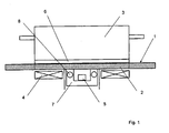
- Fig. 1 shows an embodiment of a hob according to the invention.
- the cooktop has a hob plate 1 designed as a glass ceramic plate, which has at least one cooking zone 2 for a cookware 3 to be placed on it.
- the cookware 3 is arranged by means of a heating device 4 arranged in the installed position of the hob below the hob plate 1 and designed as an induction heater. In the present embodiment, it is a hob with multiple cooking zones, of which only a single cooking zone 2 is shown and explained.
- a heat sensor unit 5 preferably at least one thermopile, arranged for non-contact temperature measurement of the temperature at the bottom 6 of the cookware 3.
- the power of the heater 4 is controlled or regulated depending on the output signals of the heat sensor unit 5 by means of the electric control.
- the heat sensor unit 5 is arranged in a receptacle 7 which is in heat-conducting contact with the underside of the hob plate 1.
- the receptacle 7 is pot-shaped and designed to be open in the direction of the underside of the hob plate 1, so that the heat radiation emanating from the bottom 6 of the cookware 3 can be detected.
- the receptacle 7 is formed with an integrated heater 8.
- the receptacle 7 forms with the heater 8 a heating block which is heated to carry out the method according to the invention for detecting the temperature at the bottom 6 of the cookware 3 and the dependent control of the power of the induction heating (heating device 4) to a defined temperature.
- the receptacle 7 may be formed in several parts.
- the heating block is heated to a desired temperature of z. B. 100 ° C heated.
- the heating block temperature is controlled either by a temperature sensor integrated in the thermopile or a separate temperature sensor in the heating block. Due to the very good heat-conducting contact of the receptacle 7 with the hob plate 1 and the glass ceramic pane is mitbebuildt in the cooking zone 2.
- the thermopile (heat sensor unit 5) is equipped with a filter that matches the transmission wavelength range of the glass-ceramic disk covers or overlaps. In this way, the heat radiation of the bottom 6 of the cookware 3 can reach the thermopile.
- thermopile can also be integrated in the receptacle 7, which is equipped with a filter which coincides with the non-transmissive wavelength range of the glass-ceramic disc.
- this Thermopile measures only the temperature on the underside of the glass ceramic pane.
- the induction heating is switched on, thus directly heating the underside of the bottom 6 of the cookware 3.
- the bottom 6 also heats the glass ceramic pane in the area of the cooking zone 2 on which the cookware 3 stands with.
- the power of the induction heating is regulated as a function of the output signal of the heat sensor unit 5 (thermopile).
- the output of the thermopile is zero.
- a thermopile principally performs a difference measurement between the actual temperature and the temperature of the receiving surface by thermal radiation.
- the temperature of the bottom 6 can be controlled very accurately by the temperature of the heating block or the temperature of the thermopile itself.
- the prerequisite is that all elements of this system (thermopile, heating block, bottom of the cookware and glass ceramic disk) are exactly at the same temperature.
Landscapes
- Physics & Mathematics (AREA)
- Electromagnetism (AREA)
- Electric Stoves And Ranges (AREA)
- Cookers (AREA)
- Induction Heating Cooking Devices (AREA)
- Control Of Resistance Heating (AREA)
Description
- Die Erfindung betrifft ein Kochfeld mit einer Kochfeldplatte insbesondere aus Glaskeramik mit mindestens einer Kochzone für ein darauf abzustellendes Kochgeschirr, einer elektrischen Steuerung zur Steuerung der Leistung einer unterhalb der Kochzone angeordnete Heizeinrichtung, wobei im Zentrum der Kochzone unterhalb der Kochfeldplatte eine Wärmesensoreinheit angeordnet ist sowie ein Verfahren zur Steuerung eines Kochprozesses auf einem derartigen Kochfeld.
- Ein derartiges Kochfeld sowie Verfahren zur Steuerung eines Kochprozesses ist aus der
DE 10 2004 002 058 B3 bekannt. Das dort beschriebene Verfahren ist für Kochfelder mit Strahlungsheizkörpern geeignet und basiert auf der exakten Messung der Wärmestrahlung des Kochgeschirrbodens und der Glaskeramikscheibe. Über die Verrechnung der Signale wird die Temperatur am Boden des Kochgeschirrs ermittelt. Zur Durchführung des Verfahrens ist die Auswertung der Ausgangssignale von mindestens zwei Wärmesensoreinheiten sowie der Vergleich mit vorher festgelegten abgespeicherten Referenzwerten erforderlich, um dann in Abhängigkeit der Ausgangssignale die Heizleistung der Heizeinrichtung zu steuern. Bei Kochfeldem ist außerdem der Einfluss des Emissionsgrades des Kochgeschirrbodens sowie der Verschmutzungsgrad der Glaskeramikscheibe auf das Messergebnis bei der Erfassung der Topfbodentemperatur zu berücksichtigen. Um diesen Einfluss berücksichtigen zu können und ein Verfahren zur optimalen Steuerung des Kochprozesses zu gestalten, sind mehrere aufwändige Sensoranordnungen erforderlich. - Der Erfindung stellt sich somit das Problem eine vom Einfluss des Emissionskoeffizienten des Kochgeschirrbodens bzw. der Verschmutzung der Glaskeramikscheibe unabhängige und einfach gestaltete Anordnung zur Erfassung der Temperatur des Kochgeschirrbodens sowie ein Verfahren zur Steuerung eines optimalen Kochprozesses mit Hitfe einer vereinfachten Sensoranordnung zu gestalten.
- Erfindungsgemäß wird dieses Problem durch ein Kochfeld mit den Merkmalen des Patentanspruchs 1 sowie ein Verfahren zur Steuerung eines Kochprozesses mit den Merkmalen des Anspruchs 3 gelöst. Vorteilhafte Ausgestaltungen und Weiterbildungen der Erfindung ergeben sich aus dem nachfolgenden Unteranspruch.
- Die mit der Erfindung erreichbaren Vorteile bestehen insbesondere darin, dass auf ein Verhältnispyrometer sowie eine Lampe zur Reflexionsmessung sowie die dazu erforderlichen Verfahrensschritte zur Auswertung der Werte verzichtet werden kann.
- Mit dem beschriebenen Verfahren wird der Einfluss des Emissionskoeffizienten des Topfbodens sowie der Einfluss des Verschmutzungsgrades der Glaskeramikscheibe eliminiert. In einem vorteilhaften Ausführungsbeispiel der Erfindung ist eine Wärmesensoreinheit mit nur einem Thermopile ausreichend, um die Temperatur des Bodens am Kochgeschirr zu erfassen.
- Ein Ausführungsbeispiel der Erfindung ist in der Zeichnung rein schematisch dargestellt und wird nachfolgend näher beschrieben. Es zeigt
- Figur 1
- ein Ausführungsbeispiel eines erfindungsgemäßen Kochfelds in der Seitenansicht im Schnitt.
-
Fig. 1 zeigt ein Ausführungsbeispiel eines erfindungsgemäßen Kochfelds. Das Kochfeld weist eine als Glaskeramikplatte ausgebildete Kochfeldplatte 1 auf, die wenigstens eine Kochzone 2 für ein darauf abzustellendes Kochgeschirr 3 aufweist. Das Kochgeschirr 3 ist mittels einer in der Einbaulage des Kochfeldes unterhalb der Kochfeldplatte 1 angeordneten und als Induktionsheizung ausgebildeten Heizeinrichtung 4 beheizbar. In dem vorliegenden Ausführungsbeispiel handelt es sich um ein Kochfeld mit mehreren Kochzonen, von denen lediglich eine einzige Kochzone 2 dargestellt und erläutert ist. Unterhalb der Kochfeldplatte 1 ist im Zentrum der Kochzone 2 eine Wärmesensoreinheit 5, vorzugsweise mindestens ein Thermopile, zur berührungslosen Temperaturmessung der Temperatur am Boden 6 des Kochgeschirrs 3 angeordnet. Die Leistung der Heizeinrichtung 4 wird in Abhängigkeit der Ausgangssignale der Wärmesensoreinheit 5 mittels der elektrischen Steuerung gesteuert oder geregelt. Die Wärmesensoreinheit 5 ist in einer Aufnahme 7 angeordnet, welche in wärmeleitenden Kontakt mit der Unterseite der Kochfeldplatte 1 steht. Die Aufnahme 7 ist topfartig und in Richtung der Unterseite der Kochfeldplatte 1 offen ausgebildet, so dass die vom Boden 6 des Kochgeschirrs 3 ausgehende Wärmestrahlung erfassbar ist. Die Aufnahme 7 ist mit einer integrierten Heizung 8 ausgebildet. Die Aufnahme 7 bildet mit der Heizung 8 einen Heizblock, der zur Durchführung des erfindungsgemäßen Verfahrens zur Erkennung der Temperatur am Boden 6 des Kochgeschirrs 3 und der davon abhängigen Steuerung der Leistung der Induktionsheizung (Heizeinrichtung 4) auf eine definierte Temperatur aufgeheizt wird. Für eine verbesserte Montage kann die Aufnahme 7 mehrteilig ausgebildet sein. - Zur Durchführung des erfindungsgemäßen Verfahrens wird der Heizblock auf eine Solltemperatur von z. B. 100°C aufgeheizt. Die Kontrolle der Heizblocktemperatur erfolgt entweder über einen im Thermopile integrierten Temperaturfühler oder einen separaten Temperaturfühler im Heizblock. Durch die sehr gut wärmeleitenden Kontaktierung der Aufnahme 7 mit der Kochfeldplatte 1 wird auch die Glaskeramikscheibe im Bereich der Kochzone 2 mitbeheizt. Der Thermopile (Wärmesensoreinheit 5) ist mit einem Filter ausgestattet, das sich mit dem Transmissionswellenlängenbereich der Glaskeramikscheibe deckt bzw. überschneidet. Auf diese Weise kann die Wärmestrahlung des Bodens 6 des Kochgeschirrs 3 den Thermopile erreichen. Optional kann in der Aufnahme 7 auch ein zweiter Thermopile integriert sein, welches mit einem Filter ausgestattet ist, das sich mit dem nicht-transmittierenden Wellenlängenbereich der Glaskeramikscheibe deckt. Auf diese Weise misst dieser Thermopile nur die Temperatur auf der Unterseite der Glaskeramikscheibe.
- Wenn der Heizblock die definierte Temperatur erreicht hat, wird die Induktionsbeheizung eingeschaltet und somit direkt die Unterseite des Bodens 6 des Kochgeschirrs 3 erwärmt. Auch der Boden 6 heizt die Glaskeramikscheibe im Bereich der Kochzone 2 auf der das Kochgeschirr 3 steht mit auf. Die Leistung der Induktionsheizung wird in Abhängigkeit des Ausgangssignals der Wärmesensoreinheit 5 (Thermopile) geregelt. Für den Fall, dass die Temperatur des Heizblockes identisch ist mit der des Thermopiles sowie der der Glaskeramikscheibe und des Bodens 6 des Kochgeschirrs 3, ist das Ausgangssignal des Thermopiles gleich Null. Hier wird die Tatsache genutzt, dass ein Thermopile prinzipiell eine Differenzmessung zwischen Eigentemperatur und der Temperatur der Empfangsfläche durch Wärmestrahlung durchführt. Auf diese Weise kann die Temperatur des Bodens 6 sehr genau über die Temperatur des Heizblockes bzw. die Eigentemperatur des Thermopiles geregelt werden. Voraussetzung ist, dass alle Elemente dieses Systems (Thermopile, Heizblock, Boden am Kochgeschirr und Glaskeramikscheibe) exakt auf der gleichen Temperatur sind.
Claims (3)
- Kochfeld mit einer Kochfeldplatte (1) insbesondere aus Glaskeramik mit mindestens einer Kochzone (2) für ein darauf abzustellendes Kochgeschirr (3), einer elektrischen Steuerung zur Steuerung der Leistung einer unterhalb der Kochzone (2) angeordneten Heizeinrichtung (4), wobei im Zentrum der Kochzone (2) unterhalb der Kochfeldplatte (1) eine Wärmesensoreinheit (5) angeordnet ist,
dadurch gekennzeichnet,
dass die Wärmesensoreinheit (5) in einer topfartig und in Richtung der Unterseite der Kochfeldplatte (1) offen ausgebildeten Aufnahme angeordnet ist, welche in wärmeleitenden Kontakt mit der Unterseite der Kochfeldplatte (1) steht und über eine integrierte Heizeinrichtung (8) beheizbar ausgebildet ist. - Kochfeld mit einer Kochfeldplatte (1) nach Anspruch 2,
dadurch gekennzeichnet,
dass die Aufnahme mehrteilig ausgebildet ist. - Verfahren zur Steuerung eines Kochprozesses bei einem Kochfeld mit einer Kochfeldplatte (1) insbesondere aus Glaskeramik mit mindestens einer Kochzone (2) für ein darauf abzustellendes Kochgeschirr (3), welches über die unterhalb der Kochzone (2) angeordnete Heizeinrichtung (4) beheizbar ist, mit einer elektrischen Steuerung zur Steuerung der Leistung der Heizeinrichtung (4) und mit einer unterhalb der Kochzone (2) angeordneten Wärmesensoreinheit (5), über die der vom Kochgeschirr (3) nach unten ausgehende Wärmestrom detektiert wird, wobei die Leistung der Heizeinrichtung (4) in Abhängigkeit der Ausgangssignale der Wärmesensoreinheit (5) mittels der elektrischen Steuerung gesteuert oder geregelt wird,
dadurch gekennzeichnet,
dass die Wärmesensoreinheit (5) sowie eine mit der Unterseite der Kochzone (2) in wärmeleitenden Kontakt stehende Aufnahme mit integrierter Heizeinrichtung (8) für die Wärmesensoreinheit (5) in einem ersten Abschnitt des Verfahrens auf eine definierte Solltemperatur aufgeheizt werden und dass nach Erreichen dieser Solltemperatur die als Induktionsheizung ausgebildete Heizeinrichtung (4) zur Beheizung des Kochgeschirrs (3) eingeschaltet wird und das die Temperatur am Boden des Kochgeschirrs (3) im Wesentlichen der Solltemperatur entspricht, wenn das Ausgangssignal der Wärmesensoreinheit (5) gleich Null ist.
Applications Claiming Priority (1)
| Application Number | Priority Date | Filing Date | Title |
|---|---|---|---|
| DE102008022387A DE102008022387A1 (de) | 2008-05-06 | 2008-05-06 | Kochfeld mit einer Kochfeldplatte sowie Verfahren zur Steuerung eines Kochprozesses |
Publications (3)
| Publication Number | Publication Date |
|---|---|
| EP2117281A2 EP2117281A2 (de) | 2009-11-11 |
| EP2117281A3 EP2117281A3 (de) | 2009-12-09 |
| EP2117281B1 true EP2117281B1 (de) | 2010-08-18 |
Family
ID=40983561
Family Applications (1)
| Application Number | Title | Priority Date | Filing Date |
|---|---|---|---|
| EP09006109A Not-in-force EP2117281B1 (de) | 2008-05-06 | 2009-05-05 | Kochfeld mit einer Kochfeldplatte sowie Verfahren zur Steuerung eines Kochprozesses |
Country Status (3)
| Country | Link |
|---|---|
| EP (1) | EP2117281B1 (de) |
| AT (1) | ATE478540T1 (de) |
| DE (2) | DE102008022387A1 (de) |
Families Citing this family (3)
| Publication number | Priority date | Publication date | Assignee | Title |
|---|---|---|---|---|
| DE102012109204A1 (de) * | 2012-09-28 | 2014-04-03 | Miele & Cie. Kg | Garsystem |
| DE102013102117A1 (de) * | 2013-03-04 | 2014-09-18 | Miele & Cie. Kg | Kocheinrichtung |
| DE102019132486B4 (de) * | 2019-11-29 | 2025-06-12 | Miele & Cie. Kg | Verfahren zur induktiven Erwärmung eines Mediums mittels eines Zubereitungskleingeräts und System zur Durchführung des Verfahrens |
Family Cites Families (7)
| Publication number | Priority date | Publication date | Assignee | Title |
|---|---|---|---|---|
| US4110588A (en) * | 1976-08-23 | 1978-08-29 | Holz George E | Indirect induction apparatus for heating fluids |
| GB2069299B (en) * | 1980-01-30 | 1983-06-22 | Riccar Co Ltd | Induction heating apparatus |
| DE19856140A1 (de) * | 1998-12-04 | 2000-06-08 | Bsh Bosch Siemens Hausgeraete | Sensorgesteuertes Kochfeld mit unterhalb der Kochfeldplatte angeordneter Sensoreinheit |
| JP4123085B2 (ja) * | 2003-07-17 | 2008-07-23 | 松下電器産業株式会社 | 誘導加熱調理器 |
| DE102004002058B3 (de) | 2004-01-15 | 2005-09-08 | Miele & Cie. Kg | Verfahren zur Steuerung eines Kochprozesses bei einem Kochfeld und Kochfeld zur Durchführung des Verfahrens |
| JP4617676B2 (ja) * | 2004-01-27 | 2011-01-26 | パナソニック株式会社 | 誘導加熱調理器 |
| EP1988751B1 (de) * | 2006-02-21 | 2014-08-27 | Panasonic Corporation | Induktionsherd |
-
2008
- 2008-05-06 DE DE102008022387A patent/DE102008022387A1/de not_active Withdrawn
-
2009
- 2009-05-05 DE DE502009000064T patent/DE502009000064D1/de active Active
- 2009-05-05 EP EP09006109A patent/EP2117281B1/de not_active Not-in-force
- 2009-05-05 AT AT09006109T patent/ATE478540T1/de active
Also Published As
| Publication number | Publication date |
|---|---|
| DE102008022387A1 (de) | 2009-11-12 |
| EP2117281A3 (de) | 2009-12-09 |
| DE502009000064D1 (de) | 2010-09-30 |
| EP2117281A2 (de) | 2009-11-11 |
| ATE478540T1 (de) | 2010-09-15 |
Similar Documents
| Publication | Publication Date | Title |
|---|---|---|
| EP1865754B1 (de) | Induktionskochmulde und Verfahren zur Ermittlung einer Temperatur eines Bodens eines Zubereitungsbehälters | |
| EP2153698B1 (de) | Verfahren zur kochfeldsteuerung und kochfeld zur durchführung des verfahrens | |
| WO2007124891A1 (de) | Vorrichtung und verfahren zur temperaturmessung an einer induktionsheizvorrichtung | |
| DE19624648A1 (de) | Spezialtopf für eine Kochfeld-Garungseinheit | |
| EP0233375A3 (de) | Glaskeramik-Kochfeld mit Heizkörpern mit in der Anheizphase schnell glühenden Heizleitern | |
| DE102005052274B4 (de) | Kochgerät | |
| EP1217873B1 (de) | Verfahren und Vorrichtung zur Erfassung der Temperatur eines Kochgefässes | |
| EP2117281A2 (de) | Kochfeld mit einer Kochfeldplatte sowie Verfahren zur Steuerung eines Kochprozesses | |
| EP0967839A2 (de) | Kochfeld mit Bedieneinheit zur Vorgabe der Leistungsstufe | |
| DE4413979C2 (de) | Sensorgesteuerte Garungseinheit und Gargerät | |
| DE102010009136B4 (de) | Vorrichtung zum Erwärmen von Flüssigkeiten | |
| DE102004059822A1 (de) | Sensorvorrichtung für ein Kochfeld, Verfahren zum Betrieb einer Sensorvorrichtung und Verwendung eines Temperatursensors als Topferkennungssensor | |
| WO2008110458A2 (de) | Kochfeldvorrichtung | |
| EP1615469A2 (de) | Kochgerät mit Temperaturerfassung und Verfahren zur Temperaturerfassung an einem Kochgerät | |
| WO2010081637A1 (de) | Kochfeld mit einer abdeckplatte | |
| DE4439777A1 (de) | Sensorgesteuerte Glaskeramik-Kochstelleneinheit | |
| EP2775792B1 (de) | Kocheinrichtung | |
| EP2649860B1 (de) | Heizvorrichtung für ein haushaltsgerät und haushaltsgerät mit einer solchen heizvorrichtung | |
| EP2775788B1 (de) | Kocheinrichtung | |
| EP3031298A1 (de) | Kocheinrichtung und verfahren zum betreiben einer kocheinrichtung | |
| EP2775787B1 (de) | Kocheinrichtung | |
| DE19827298C1 (de) | Kochstelle mit einer Induktionskochzone | |
| DE19820108A1 (de) | Anordnung eines wärmeleitenden keramischen Trägers mit einem Heizkörper als Kochzone in einer Aussparung einer Kochfläche | |
| EP1980135A1 (de) | Ebenes strahlungsbeheiztes heizelement | |
| EP3031297B1 (de) | Kocheinrichtung und verfahren zum betreiben der kocheinrichtung |
Legal Events
| Date | Code | Title | Description |
|---|---|---|---|
| PUAI | Public reference made under article 153(3) epc to a published international application that has entered the european phase |
Free format text: ORIGINAL CODE: 0009012 |
|
| PUAL | Search report despatched |
Free format text: ORIGINAL CODE: 0009013 |
|
| AK | Designated contracting states |
Kind code of ref document: A2 Designated state(s): AT BE BG CH CY CZ DE DK EE ES FI FR GB GR HR HU IE IS IT LI LT LU LV MC MK MT NL NO PL PT RO SE SI SK TR |
|
| AK | Designated contracting states |
Kind code of ref document: A3 Designated state(s): AT BE BG CH CY CZ DE DK EE ES FI FR GB GR HR HU IE IS IT LI LT LU LV MC MK MT NL NO PL PT RO SE SI SK TR |
|
| 17P | Request for examination filed |
Effective date: 20100203 |
|
| GRAP | Despatch of communication of intention to grant a patent |
Free format text: ORIGINAL CODE: EPIDOSNIGR1 |
|
| GRAS | Grant fee paid |
Free format text: ORIGINAL CODE: EPIDOSNIGR3 |
|
| GRAA | (expected) grant |
Free format text: ORIGINAL CODE: 0009210 |
|
| AK | Designated contracting states |
Kind code of ref document: B1 Designated state(s): AT BE BG CH CY CZ DE DK EE ES FI FR GB GR HR HU IE IS IT LI LT LU LV MC MK MT NL NO PL PT RO SE SI SK TR |
|
| REG | Reference to a national code |
Ref country code: GB Ref legal event code: FG4D Free format text: NOT ENGLISH |
|
| REG | Reference to a national code |
Ref country code: CH Ref legal event code: EP |
|
| REG | Reference to a national code |
Ref country code: IE Ref legal event code: FG4D Free format text: LANGUAGE OF EP DOCUMENT: GERMAN |
|
| REG | Reference to a national code |
Ref country code: GB Ref legal event code: 746 Effective date: 20100907 |
|
| REF | Corresponds to: |
Ref document number: 502009000064 Country of ref document: DE Date of ref document: 20100930 Kind code of ref document: P |
|
| REG | Reference to a national code |
Ref country code: NL Ref legal event code: VDEP Effective date: 20100818 |
|
| LTIE | Lt: invalidation of european patent or patent extension |
Effective date: 20100818 |
|
| PG25 | Lapsed in a contracting state [announced via postgrant information from national office to epo] |
Ref country code: LT Free format text: LAPSE BECAUSE OF FAILURE TO SUBMIT A TRANSLATION OF THE DESCRIPTION OR TO PAY THE FEE WITHIN THE PRESCRIBED TIME-LIMIT Effective date: 20100818 Ref country code: NO Free format text: LAPSE BECAUSE OF FAILURE TO SUBMIT A TRANSLATION OF THE DESCRIPTION OR TO PAY THE FEE WITHIN THE PRESCRIBED TIME-LIMIT Effective date: 20101118 Ref country code: FI Free format text: LAPSE BECAUSE OF FAILURE TO SUBMIT A TRANSLATION OF THE DESCRIPTION OR TO PAY THE FEE WITHIN THE PRESCRIBED TIME-LIMIT Effective date: 20100818 |
|
| PG25 | Lapsed in a contracting state [announced via postgrant information from national office to epo] |
Ref country code: IS Free format text: LAPSE BECAUSE OF FAILURE TO SUBMIT A TRANSLATION OF THE DESCRIPTION OR TO PAY THE FEE WITHIN THE PRESCRIBED TIME-LIMIT Effective date: 20101218 Ref country code: SI Free format text: LAPSE BECAUSE OF FAILURE TO SUBMIT A TRANSLATION OF THE DESCRIPTION OR TO PAY THE FEE WITHIN THE PRESCRIBED TIME-LIMIT Effective date: 20100818 Ref country code: HR Free format text: LAPSE BECAUSE OF FAILURE TO SUBMIT A TRANSLATION OF THE DESCRIPTION OR TO PAY THE FEE WITHIN THE PRESCRIBED TIME-LIMIT Effective date: 20100818 Ref country code: CY Free format text: LAPSE BECAUSE OF FAILURE TO SUBMIT A TRANSLATION OF THE DESCRIPTION OR TO PAY THE FEE WITHIN THE PRESCRIBED TIME-LIMIT Effective date: 20100818 Ref country code: BG Free format text: LAPSE BECAUSE OF FAILURE TO SUBMIT A TRANSLATION OF THE DESCRIPTION OR TO PAY THE FEE WITHIN THE PRESCRIBED TIME-LIMIT Effective date: 20101118 Ref country code: PL Free format text: LAPSE BECAUSE OF FAILURE TO SUBMIT A TRANSLATION OF THE DESCRIPTION OR TO PAY THE FEE WITHIN THE PRESCRIBED TIME-LIMIT Effective date: 20100818 |
|
| REG | Reference to a national code |
Ref country code: IE Ref legal event code: FD4D |
|
| PG25 | Lapsed in a contracting state [announced via postgrant information from national office to epo] |
Ref country code: GR Free format text: LAPSE BECAUSE OF FAILURE TO SUBMIT A TRANSLATION OF THE DESCRIPTION OR TO PAY THE FEE WITHIN THE PRESCRIBED TIME-LIMIT Effective date: 20101119 Ref country code: NL Free format text: LAPSE BECAUSE OF FAILURE TO SUBMIT A TRANSLATION OF THE DESCRIPTION OR TO PAY THE FEE WITHIN THE PRESCRIBED TIME-LIMIT Effective date: 20100818 Ref country code: LV Free format text: LAPSE BECAUSE OF FAILURE TO SUBMIT A TRANSLATION OF THE DESCRIPTION OR TO PAY THE FEE WITHIN THE PRESCRIBED TIME-LIMIT Effective date: 20100818 Ref country code: SE Free format text: LAPSE BECAUSE OF FAILURE TO SUBMIT A TRANSLATION OF THE DESCRIPTION OR TO PAY THE FEE WITHIN THE PRESCRIBED TIME-LIMIT Effective date: 20100818 |
|
| PG25 | Lapsed in a contracting state [announced via postgrant information from national office to epo] |
Ref country code: DK Free format text: LAPSE BECAUSE OF FAILURE TO SUBMIT A TRANSLATION OF THE DESCRIPTION OR TO PAY THE FEE WITHIN THE PRESCRIBED TIME-LIMIT Effective date: 20100818 Ref country code: IE Free format text: LAPSE BECAUSE OF FAILURE TO SUBMIT A TRANSLATION OF THE DESCRIPTION OR TO PAY THE FEE WITHIN THE PRESCRIBED TIME-LIMIT Effective date: 20100818 |
|
| PG25 | Lapsed in a contracting state [announced via postgrant information from national office to epo] |
Ref country code: EE Free format text: LAPSE BECAUSE OF FAILURE TO SUBMIT A TRANSLATION OF THE DESCRIPTION OR TO PAY THE FEE WITHIN THE PRESCRIBED TIME-LIMIT Effective date: 20100818 Ref country code: CZ Free format text: LAPSE BECAUSE OF FAILURE TO SUBMIT A TRANSLATION OF THE DESCRIPTION OR TO PAY THE FEE WITHIN THE PRESCRIBED TIME-LIMIT Effective date: 20100818 Ref country code: RO Free format text: LAPSE BECAUSE OF FAILURE TO SUBMIT A TRANSLATION OF THE DESCRIPTION OR TO PAY THE FEE WITHIN THE PRESCRIBED TIME-LIMIT Effective date: 20100818 Ref country code: SK Free format text: LAPSE BECAUSE OF FAILURE TO SUBMIT A TRANSLATION OF THE DESCRIPTION OR TO PAY THE FEE WITHIN THE PRESCRIBED TIME-LIMIT Effective date: 20100818 |
|
| PLBE | No opposition filed within time limit |
Free format text: ORIGINAL CODE: 0009261 |
|
| STAA | Information on the status of an ep patent application or granted ep patent |
Free format text: STATUS: NO OPPOSITION FILED WITHIN TIME LIMIT |
|
| PG25 | Lapsed in a contracting state [announced via postgrant information from national office to epo] |
Ref country code: ES Free format text: LAPSE BECAUSE OF FAILURE TO SUBMIT A TRANSLATION OF THE DESCRIPTION OR TO PAY THE FEE WITHIN THE PRESCRIBED TIME-LIMIT Effective date: 20101129 |
|
| 26N | No opposition filed |
Effective date: 20110519 |
|
| REG | Reference to a national code |
Ref country code: DE Ref legal event code: R097 Ref document number: 502009000064 Country of ref document: DE Effective date: 20110519 |
|
| BERE | Be: lapsed |
Owner name: MIELE & CIE. K.G. Effective date: 20110531 |
|
| PG25 | Lapsed in a contracting state [announced via postgrant information from national office to epo] |
Ref country code: MC Free format text: LAPSE BECAUSE OF NON-PAYMENT OF DUE FEES Effective date: 20110531 Ref country code: MT Free format text: LAPSE BECAUSE OF FAILURE TO SUBMIT A TRANSLATION OF THE DESCRIPTION OR TO PAY THE FEE WITHIN THE PRESCRIBED TIME-LIMIT Effective date: 20100818 |
|
| PG25 | Lapsed in a contracting state [announced via postgrant information from national office to epo] |
Ref country code: BE Free format text: LAPSE BECAUSE OF NON-PAYMENT OF DUE FEES Effective date: 20110531 |
|
| PG25 | Lapsed in a contracting state [announced via postgrant information from national office to epo] |
Ref country code: MK Free format text: LAPSE BECAUSE OF FAILURE TO SUBMIT A TRANSLATION OF THE DESCRIPTION OR TO PAY THE FEE WITHIN THE PRESCRIBED TIME-LIMIT Effective date: 20100818 |
|
| PG25 | Lapsed in a contracting state [announced via postgrant information from national office to epo] |
Ref country code: LU Free format text: LAPSE BECAUSE OF NON-PAYMENT OF DUE FEES Effective date: 20110505 |
|
| PG25 | Lapsed in a contracting state [announced via postgrant information from national office to epo] |
Ref country code: PT Free format text: LAPSE BECAUSE OF NON-PAYMENT OF DUE FEES Effective date: 20100818 |
|
| PG25 | Lapsed in a contracting state [announced via postgrant information from national office to epo] |
Ref country code: TR Free format text: LAPSE BECAUSE OF FAILURE TO SUBMIT A TRANSLATION OF THE DESCRIPTION OR TO PAY THE FEE WITHIN THE PRESCRIBED TIME-LIMIT Effective date: 20100818 |
|
| PG25 | Lapsed in a contracting state [announced via postgrant information from national office to epo] |
Ref country code: HU Free format text: LAPSE BECAUSE OF FAILURE TO SUBMIT A TRANSLATION OF THE DESCRIPTION OR TO PAY THE FEE WITHIN THE PRESCRIBED TIME-LIMIT Effective date: 20100818 |
|
| REG | Reference to a national code |
Ref country code: CH Ref legal event code: PL |
|
| PG25 | Lapsed in a contracting state [announced via postgrant information from national office to epo] |
Ref country code: LI Free format text: LAPSE BECAUSE OF NON-PAYMENT OF DUE FEES Effective date: 20130531 Ref country code: CH Free format text: LAPSE BECAUSE OF NON-PAYMENT OF DUE FEES Effective date: 20130531 |
|
| REG | Reference to a national code |
Ref country code: AT Ref legal event code: MM01 Ref document number: 478540 Country of ref document: AT Kind code of ref document: T Effective date: 20140505 |
|
| PG25 | Lapsed in a contracting state [announced via postgrant information from national office to epo] |
Ref country code: AT Free format text: LAPSE BECAUSE OF NON-PAYMENT OF DUE FEES Effective date: 20140505 |
|
| REG | Reference to a national code |
Ref country code: FR Ref legal event code: PLFP Year of fee payment: 8 |
|
| REG | Reference to a national code |
Ref country code: FR Ref legal event code: PLFP Year of fee payment: 9 |
|
| REG | Reference to a national code |
Ref country code: FR Ref legal event code: PLFP Year of fee payment: 10 |
|
| PGFP | Annual fee paid to national office [announced via postgrant information from national office to epo] |
Ref country code: IT Payment date: 20220519 Year of fee payment: 14 Ref country code: GB Payment date: 20220524 Year of fee payment: 14 Ref country code: FR Payment date: 20220526 Year of fee payment: 14 Ref country code: DE Payment date: 20220531 Year of fee payment: 14 |
|
| P01 | Opt-out of the competence of the unified patent court (upc) registered |
Effective date: 20230529 |
|
| REG | Reference to a national code |
Ref country code: DE Ref legal event code: R119 Ref document number: 502009000064 Country of ref document: DE |
|
| GBPC | Gb: european patent ceased through non-payment of renewal fee |
Effective date: 20230505 |
|
| PG25 | Lapsed in a contracting state [announced via postgrant information from national office to epo] |
Ref country code: IT Free format text: LAPSE BECAUSE OF NON-PAYMENT OF DUE FEES Effective date: 20230505 Ref country code: DE Free format text: LAPSE BECAUSE OF NON-PAYMENT OF DUE FEES Effective date: 20231201 Ref country code: GB Free format text: LAPSE BECAUSE OF NON-PAYMENT OF DUE FEES Effective date: 20230505 |
|
| PG25 | Lapsed in a contracting state [announced via postgrant information from national office to epo] |
Ref country code: FR Free format text: LAPSE BECAUSE OF NON-PAYMENT OF DUE FEES Effective date: 20230531 |