EP2117380B1 - AUSSTOßER FÜR EIN BEWEGBARES MÖBELTEIL - Google Patents
AUSSTOßER FÜR EIN BEWEGBARES MÖBELTEIL Download PDFInfo
- Publication number
- EP2117380B1 EP2117380B1 EP07845291A EP07845291A EP2117380B1 EP 2117380 B1 EP2117380 B1 EP 2117380B1 EP 07845291 A EP07845291 A EP 07845291A EP 07845291 A EP07845291 A EP 07845291A EP 2117380 B1 EP2117380 B1 EP 2117380B1
- Authority
- EP
- European Patent Office
- Prior art keywords
- ejector
- ejector lever
- drive unit
- lever
- furniture
- Prior art date
- Legal status (The legal status is an assumption and is not a legal conclusion. Google has not performed a legal analysis and makes no representation as to the accuracy of the status listed.)
- Active
Links
Images
Classifications
-
- E—FIXED CONSTRUCTIONS
- E05—LOCKS; KEYS; WINDOW OR DOOR FITTINGS; SAFES
- E05B—LOCKS; ACCESSORIES THEREFOR; HANDCUFFS
- E05B17/00—Accessories in connection with locks
- E05B17/0025—Devices for forcing the wing firmly against its seat or to initiate the opening of the wing
- E05B17/0029—Devices for forcing the wing firmly against its seat or to initiate the opening of the wing motor-operated
-
- A—HUMAN NECESSITIES
- A47—FURNITURE; DOMESTIC ARTICLES OR APPLIANCES; COFFEE MILLS; SPICE MILLS; SUCTION CLEANERS IN GENERAL
- A47B—TABLES; DESKS; OFFICE FURNITURE; CABINETS; DRAWERS; GENERAL DETAILS OF FURNITURE
- A47B88/00—Drawers for tables, cabinets or like furniture; Guides for drawers
- A47B88/40—Sliding drawers; Slides or guides therefor
- A47B88/453—Actuated drawers
- A47B88/46—Actuated drawers operated by mechanically-stored energy, e.g. by springs
- A47B88/463—Actuated drawers operated by mechanically-stored energy, e.g. by springs self-opening
-
- E—FIXED CONSTRUCTIONS
- E05—LOCKS; KEYS; WINDOW OR DOOR FITTINGS; SAFES
- E05B—LOCKS; ACCESSORIES THEREFOR; HANDCUFFS
- E05B17/00—Accessories in connection with locks
- E05B17/22—Means for operating or controlling lock or fastening device accessories, i.e. other than the fastening members, e.g. switches, indicators
Definitions
- the present invention relates to an ejector for ejecting a movable furniture part from a closed end position in or on a furniture body, with a by a electric drive unit, in particular electric motor, drivable first ejection lever.
- the object of the invention is therefore to develop a single generic ejector such that it overcomes at least one of the problems discussed above.
- the problem of triggering which is difficult to detect in the center can also be remedied if it is provided that the further ejection lever is mechanically coupled to the first ejection lever in such a way as to further agitate Ejection lever is detectable by a movement of the first ejection lever monitoring sensor.
- a further advantage is that in both discussed embodiments mounting on the rear wall or a side wall of the furniture body while avoiding a carrier profile is possible.
- a particularly simple embodiment for the mechanical coupling is a rod.
- Protection is also desired for a piece of furniture with a furniture body and an ejector according to one of the aforementioned embodiments, wherein the first ejection lever and the further ejection lever are arranged on opposite side walls of the furniture body.
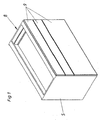
- Fig. 1 shows a piece of furniture 8 with a furniture body 5 and three movably mounted in the furniture body furniture parts 9, which are formed in this embodiment as drawers.
- the invention can also be used in furniture parts 9 designed as furniture doors.
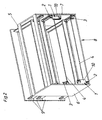
- Fig. 2 shows that in Fig. 1 shown furniture 8 with the rear wall removed and partly out of the furniture body 5 moving movable furniture parts.
- an ejector 1 for the lowermost two movable furniture parts 9 an ejector 1 according to the invention are respectively provided.
- the first ejection lever 2 is arranged on the side wall 6, while the further ejection lever 3 is arranged on the side wall 7.
- the arrangement is exactly reversed.
- Each ejector 1 has a housing part 10, in which the electric drive unit, a control unit for the drive unit, a transmission and a sensor (for example rotary potentiometer) for detecting the movement of the first ejection lever 2 are arranged.
- a sensor for example rotary potentiometer
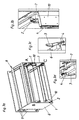
- Fig. 3 and 4 show detail views to the in Fig. 1 and 2 illustrated furniture 8.
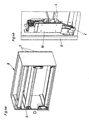
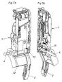
- the Fig. 5a shows an ejector 1 according to the invention with the first ejection lever 2, wherein it can be seen that in this embodiment with the rod 4, a driver 12th rotatably connected.
- the driver 12 is designed and arranged relative to the first ejection lever 2, that it rotates with a slight rotation of the rod 4. This is important if a triggering of the ejector 1 is to take place by an actuation of the further ejection lever 3.
- the movable furniture part 9 is pressed on that side of the furniture body 7, on which the further ejection lever 3 is arranged in the furniture body 8, this movement is transmitted via the rod 4 on the driver 12 and thus on the first ejection lever 2.
- the first ejection lever 2 is coupled via a toothing 13 with a rotary potentiometer. After detection of a movement by the rotary potentiometer, the activation of the electric drive unit of the ejector 1 and the movable furniture part 9 is ejected.
- Fig. 5b the storage of the rod 4 in the ejector 1 on the part 11 can be seen. It is a floating storage, that is, the rod 4 can be rotated without being hindered by the self-locking of the electric drive unit.
- the first ejection lever 2 has a certain amount of play in order to be able to move it slightly without being inhibited by the transmission.
- Such training is for example in the AT 413 472 B in Fig. 17 and the corresponding point of description disclosed and therefore need not be explained in detail at this point.
Landscapes
- Engineering & Computer Science (AREA)
- Mechanical Engineering (AREA)
- Drawers Of Furniture (AREA)
- Jet Pumps And Other Pumps (AREA)
- Power-Operated Mechanisms For Wings (AREA)
- Sheet Holders (AREA)
- Perforating, Stamping-Out Or Severing By Means Other Than Cutting (AREA)
Description
- Die vorliegende Erfindung betrifft einen Ausstoßer zum Ausstoßen eines bewegbaren Möbelteils aus einer geschlossenen Endlage in bzw. an einem Möbelkorpus, mit einem durch eine elektrische Antriebseinheit, insbesondere Elektromotor, antreibbaren ersten Ausstoßhebel.
- Besonders bei sehr breiten bewegbaren Möbelteilen, insbesondere sehr breiten Schubläden, werden gattungsgemäße Ausstoßer in der Regel mittig am Möbelkorpus angeordnet, da es bei einer einseitigen dezentralen Anordnung zu einer ungünstigen Kraftausübung (Gefahr des Verkantens) auf das bewegbare Möbelteil kommt siehe z.B.
WO2007/006061 A1 . - Andererseits ist es bei gattungsgemäßen Ausstoßern wünschenswert, diese mit einer Touch-Latch-Funktionalität zu versehen, das heißt diese derart auszugestalten, dass sie bei einer Zug- oder Druckausübung auf den Ausstoßhebel die elektrische Antriebseinheit aktivieren und das bewegbare Möbelteil aus der geschlossenen Endlage ausstoßen. Um diese Funktionalität im vollen Umfang, das heißt auch für eine druckinduzierte Auslösung zuzulassen, ist es natürlich notwendig, auch in der geschlossenen Endlage des bewegbaren Möbelteils noch genug Freiraum für eine geringfügige Bewegung des bewegbaren Möbelteils in den Möbelkorpus hinein bzw. auf diesen zu zuzulassen. Gerade bei sehr breiten bewegbaren Möbelteilen ist die oben beschriebene mittige Anordnung eines Ausstoßers hinsichtlich der Touch-Latch-Funktionalität problematisch, da nicht davon ausgegangen werden kann, dass jeder Benutzer die für die Auslösung notwendige Kraft mittig auf das bewegbare Möbelteil aufbringt.
- Unabhängig davon, ob gattungsgemäße Ausstoßer eine Touch-Latch-Funktionalität aufweisen, hat es sich herausgestellt, dass auch die mittige Anordnung eines Ausstoßers bei einem sehr breiten bewegbaren Möbelteil hinsichtlich der Kraftausübung nicht optimal ist. Genau im mittigen Bereich des bewegbaren Möbelteils tritt nämlich eine relativ große Verformung des bewegbaren Möbelteils, zum Beispiel der Schubladenrückwand auf.
- Beide diskutierten Probleme könnten natürlich durch die Anordnung von zwei Ausstoßern jeweils in der Nähe der einander gegenüberliegenden Seitenwänden des Möbelkorpus vermieden werden. Diese Lösung ist allerdings aus wirtschaftlichen Gründen nicht wünschenswert.
- Aufgabe der Erfindung ist es daher einen einzelnen gattungsgemäßen Ausstoßer derart weiterzuentwickeln, dass er zumindest eines der oben diskutierten Probleme behebt.
- Diese Aufgabe wird durch einen Ausstoßer mit den Merkmalen des Anspruchs 1 gelöst.
- Durch das Vorsehen eines weiteren Ausstoßhebels, welcher mit dem ersten Ausstoßhebel mechanisch gekoppelt ist, entfällt die Notwendigkeit zwei gesonderte Ausstoßer im Möbelkoprus anzuordnen. Gleichzeitig wird zumindest das Problem der ungünstigen Kraftausübung auf das bewegbare Möbelteil behoben, da bei einem Ausstoßer nach Anspruch 1 die Kraft am Rand des bewegbaren Möbelteils aufgebracht wird, wodurch sich eine geringere Verformung des bewegbaren Möbelteils ergibt.
- Ist vorgesehen, dass der Ausstoßer eine Touch-Latch-Funktionalität aufweist, so kann auch das Problem der mittig nur schwer detektierbaren Auslösung behoben werden, wenn vorgesehen ist, dass der weitere Ausstoßhebel derart mit dem ersten Ausstoßhebel mechanisch gekoppelt ist, dass eine Bewegung des weiteren Ausstoßhebels durch einen eine Bewegung des ersten Ausstoßhebels überwachenden Sensor detektierbar ist.
- Dies gestattet es eine in der Nähe beider einander gegenüberliegenden Seitenwände auf das bewegbare Möbelteil ausgeübte Kraft zu detektieren.
- Vorteilhaft ist weiters, dass bei beiden diskutierten Ausführungsbeispielen eine Montage an der Rückwand oder einer Seitenwand des Möbelkorpus unter Vermeidung eines Trägerprofils möglich ist.
- Eine besonders einfache Ausführungsform für die mechanische Koppelung stellt eine Stange dar.
- Es sind aber prinzipiell auch aufwendigere mechanische Vorrichtungen zum mechanischen Koppeln der Ausstoßhebel, wie beispielsweise ein Hebelwerk, denkbar.
- Schutz wird auch begehrt für ein Möbel mit einem Möbelkorpus und einem Ausstoßer nach einem der vorgenannten Ausführungsbeispiele, wobei der erste Ausstoßhebel und der weitere Ausstoßhebel an einander gegenüberliegenden Seitenwänden des Möbelkorpus angeordnet sind.
- Weitere Vorteile und Einzelheiten der Erfindung ergeben sich anhand der Figuren sowie der Figurenbeschreibung. Dabei zeigen:
- Fig. 1
- eine perspektivische Ansicht eines Möbels,
- Fig. 2
- eine perspektivische Ansicht des in
Fig. 1 dargestellten Möbels bei entfernter Rückwand, - Fig. 3a bis 3d
- eine Darstellung entsprechend
Fig. 2 sowie Detailansichten hierzu, - Fig. 4a, 4b
- eine weitere Darstellung entsprechend
Fig. 2 mit einer weiteren Detailansicht, - Fig. 5a, 5b
- eine Detaildarstellung eines erfindungsgemäßen Ausstoßers in perspektivischer Ansicht und einer Schnittdarstellung durch die Mittelebene.
-
Fig. 1 zeigt ein Möbel 8 mit einem Möbelkorpus 5 und drei im Möbelkorpus bewegbar gelagerten Möbelteilen 9, welche in diesem Ausführungsbeispiel als Schubladen ausgebildet sind. Die Erfindung lässt sich jedoch auch bei als Möbeltüren ausgebildeten bewegbaren Möbelteilen 9 einsetzen. -
Fig. 2 zeigt das inFig. 1 dargestellte Möbel 8 bei entfernter Rückwand und teilweise aus dem Möbelkorpus 5 heraus bewegten bewegbaren Möbelteilen 9. - Für die untersten beiden bewegbaren Möbelteile 9 sind jeweils ein erfindungsgemäßer Ausstoßer 1 vorgesehen. Beim untersten bewegbaren Möbelteil 9 ist dabei der erste Ausstoßhebel 2 an der Seitenwand 6 angeordnet, während der weitere Ausstoßhebel 3 an der Seitenwand 7 angeordnet ist. Beim mittleren bewegbaren Möbelteil 9 ist die Anordnung genau umgedreht.
- Jeder Ausstoßer 1 verfügt über einen Gehäuseteil 10, in welchem die elektrische Antriebseinheit, eine Steuer- bzw. Regeleinrichtung für die Antriebseinheit, ein Getriebe und ein Sensor (zum Beispiel Drehpotentiometer) zum Detektieren der Bewegung des ersten Ausstoßhebels 2 angeordnet sind.
- Die
Fig. 3 und4 zeigen Detailansichten zu dem inFig. 1 und2 dargestellten Möbel 8. - Die
Fig. 5a zeigt einen erfindungsgemäßen Ausstoßer 1 mit dem ersten Ausstoßhebel 2, wobei erkennbar ist, dass in diesem Ausführungsbeispiel mit der Stange 4 ein Mitnehmer 12 drehfest verbunden ist. Der Mitnehmer 12 ist dabei so ausgebildet und relativ zum ersten Ausstoßhebel 2 angeordnet, dass er diesen bei einer leichten Verdrehung der Stange 4 mitdreht. Dies ist von Bedeutung, wenn durch eine Betätigung des weiteren Ausstoßhebels 3 eine Auslösung des Ausstoßers 1 erfolgen soll. - Wird nämlich das bewegbare Möbelteil 9 auf jener Seite des Möbelkorpus 7, auf welcher der weitere Ausstoßhebel 3 angeordnet ist, in den Möbelkorpus 8 eingedrückt, so wird diese Bewegung über die Stange 4 auf den Mitnehmer 12 und damit auf den ersten Ausstoßhebel 2 übertragen. Der erste Ausstoßhebel 2 ist über eine Zahnung 13 mit einem Drehpotentiometer gekoppelt. Nach erfolgter Detektion einer Bewegung durch das Drehpotentiometer erfolgt die Aktivierung der elektrischen Antriebseinheit des Ausstoßers 1 und das bewegbare Möbelteil 9 wird ausgestoßen.
- Aus
Fig. 5b ist die Lagerung der Stange 4 im Ausstoßer 1 auf dem Teil 11 ersichtlich. Dabei handelt es sich um eine schwimmende Lagerung, das heißt, die Stange 4 kann gedreht werden, ohne durch die Selbsthemmung der elektrischen Antriebseinheit daran gehindert zu werden. Natürlich weist auch der erste Ausstoßhebel 2 ein gewisses Spiel auf, um diesen ohne Hemmung durch das Getriebe geringfügig bewegen zu können. Eine derartige Ausbildung ist beispielsweise in derAT 413 472 B - In allen Figuren wurde auf die Darstellung elektrischer Versorgungsleitungen und dergleichen verzichtet.
Claims (3)
- Ausstoßer zum Ausstoßen eines bewegbaren Möbelteils aus einer geschlossenen Endlage in bzw. an einem Möbelkorpus, mit einem durch eine elektrische Antriebseinheit, insbesondere Elektromotor, antreibbaren ersten Ausstoßhebel und einer Steuer- bzw. Regeleinrichtung für die Antriebseinheit dadurch gekennzeichnet dass ein weiterer Ausstoßhebel vorgesehen ist, der vom ersten Ausstoßhebel beabstandet und mit diesem durch eine mechanische Koppelung gekoppelt ist, sodass ein Antreiben des ersten Ausstoßhebels durch die Antriebseinheit auch den weiteren Ausstoßhebel bewegt, und, das über die mechanische Koppelung eine Bewegung des weiteren Ausstoßhebels (3) durch einen eine Bewegung des ersten Ausstoßhebels (2) überwachenden Sensor detektierbar ist und dass die Steuer- bzw. Regeleinrichtung nach erfolgter Detektion die Antriebseinheit aktiviert.
- Ausstoßer nach Anspruch 1, dadurch gekennzeichnet, dass der weitere Ausstoßhebel (3) mit dem ersten Ausstoßhebel (2) durch eine Stange (4) verbunden ist.
- Möbel mit einem Möbelkorpus und einem Ausstoßer nach Anspruch 1 oder 2, dadurch gekennzeichnet, dass der erste Ausstoßhebel (2) und der weitere Ausstoßhebel (3) an einander gegenüberliegenden Seitenwänden (6, 7) des Möbelkorpus (5) angeordnet sind.
Applications Claiming Priority (2)
| Application Number | Priority Date | Filing Date | Title |
|---|---|---|---|
| AT0024007A AT504509B1 (de) | 2007-02-15 | 2007-02-15 | Ausstosser für ein bewegbares möbelteil |
| PCT/AT2007/000562 WO2008098266A2 (de) | 2007-02-15 | 2007-12-11 | AUSSTOßER FÜR EIN BEWEGBARES MÖBELTEIL |
Publications (2)
| Publication Number | Publication Date |
|---|---|
| EP2117380A2 EP2117380A2 (de) | 2009-11-18 |
| EP2117380B1 true EP2117380B1 (de) | 2010-07-21 |
Family
ID=39494783
Family Applications (1)
| Application Number | Title | Priority Date | Filing Date |
|---|---|---|---|
| EP07845291A Active EP2117380B1 (de) | 2007-02-15 | 2007-12-11 | AUSSTOßER FÜR EIN BEWEGBARES MÖBELTEIL |
Country Status (9)
| Country | Link |
|---|---|
| US (1) | US20090284114A1 (de) |
| EP (1) | EP2117380B1 (de) |
| JP (1) | JP2010518292A (de) |
| CN (1) | CN101605480B (de) |
| AT (2) | AT504509B1 (de) |
| DE (1) | DE502007004522D1 (de) |
| ES (1) | ES2348821T3 (de) |
| MY (1) | MY147691A (de) |
| WO (1) | WO2008098266A2 (de) |
Families Citing this family (10)
| Publication number | Priority date | Publication date | Assignee | Title |
|---|---|---|---|---|
| AT506642B1 (de) * | 2008-03-17 | 2014-03-15 | Blum Gmbh Julius | Stellanordnung mit zwei stellvorrichtungen |
| AT507805B1 (de) * | 2009-01-16 | 2013-09-15 | Blum Gmbh Julius | Auslösesensor für einen möbelantrieb |
| AT507656B1 (de) * | 2009-05-13 | 2010-07-15 | Blum Gmbh Julius | Anordnung zum verriegeln und ausstossen eines möbelteils |
| AT509702B1 (de) * | 2010-04-19 | 2011-11-15 | Blum Gmbh Julius | Ausstosser zum ausstossen eines bewegbaren möbelteils |
| AT510257B1 (de) | 2010-10-15 | 2012-03-15 | Blum Gmbh Julius | Positioniervorrichtung zum positionieren einer ausstossvorrichtung zum ausstossen eines bewegbar gelagerten möbelteiles |
| AT511511B1 (de) * | 2011-05-20 | 2015-05-15 | Blum Gmbh Julius | Synchronisationsvorrichtung für ein bewegbar gelagertes möbelteil |
| AT512509B1 (de) * | 2012-07-10 | 2013-09-15 | Blum Gmbh Julius | Ausstoßvorrichtung für ein bewegbares Möbelteil |
| DE202015104437U1 (de) * | 2015-08-21 | 2016-11-22 | Grass Gmbh | Vorrichtung zum Bewegen eines bewegbaren Möbelteils in eine Öffnungsrichtung in Bezug zu einem Möbelkorpus eines Möbels |
| CN106820786B (zh) * | 2017-02-28 | 2019-11-15 | 浙江美拓智能科技有限公司 | 一种电子产品展示柜台 |
| JP7212312B2 (ja) * | 2019-03-26 | 2023-01-25 | Toto株式会社 | キャビネット |
Family Cites Families (13)
| Publication number | Priority date | Publication date | Assignee | Title |
|---|---|---|---|---|
| CH548182A (de) * | 1972-04-19 | 1974-04-30 | Sperry Rand Corp | Vorrichtung fuer schubladenschrank, zum aus- und einfahren der schubladen. |
| US4934767A (en) * | 1986-05-16 | 1990-06-19 | Thermco Systems, Inc. | Semiconductor wafer carrier input/output drawer |
| US5158347A (en) * | 1990-02-21 | 1992-10-27 | Meridian Incorporated | Subcabinet movement initiator |
| CH691460A5 (de) * | 1995-08-25 | 2001-07-31 | Sarnatech Paulmann & Crone | Vorrichtung zum Verriegeln und Entriegeln eines Becherhalters. |
| DE10157754A1 (de) * | 2001-11-27 | 2003-06-26 | Grass Gmbh Hoechst | Vorrichtung zum Öffnen und Schließen eines beweglichen Möbelteils |
| AT500362B1 (de) * | 2002-06-27 | 2007-01-15 | Blum Gmbh Julius | Anordnung mit einem bewegbaren möbelteil und mit einer antriebseinheit |
| AT502574B1 (de) * | 2003-05-19 | 2007-08-15 | Blum Gmbh Julius | Möbel mit einem bewegbaren möbelteil |
| AT413472B (de) * | 2004-08-16 | 2006-03-15 | Blum Gmbh Julius | Ausstossvorrichtung für ein bewegbares möbelteil |
| DE102004045567A1 (de) * | 2004-09-17 | 2006-04-06 | Küster Automotive Door Systems GmbH | Verstellvorrichtung zum Verstellen, insbesondere zum translatorischen Verschieben, eines Möbelteils |
| AT501778B1 (de) * | 2005-04-28 | 2009-11-15 | Blum Gmbh Julius | Ausstossvorrichtung für ein bewegbares möbelteil |
| AT502097B1 (de) * | 2005-07-12 | 2010-01-15 | Blum Gmbh Julius | Möbel mit ausstossvorrichtung für schubladen |
| AT8730U1 (de) * | 2005-07-25 | 2006-12-15 | Grass Gmbh | Vorrichtung zum öffnen und schliessen eines beweglichen möbelteils od. dgl. |
| AT504838B1 (de) * | 2007-02-15 | 2008-12-15 | Blum Gmbh Julius | Vorrichtung zum ausstossen eines bewegbaren möbelteils |
-
2007
- 2007-02-15 AT AT0024007A patent/AT504509B1/de not_active IP Right Cessation
- 2007-12-11 ES ES07845291T patent/ES2348821T3/es active Active
- 2007-12-11 JP JP2009549739A patent/JP2010518292A/ja active Pending
- 2007-12-11 AT AT07845291T patent/ATE474472T1/de active
- 2007-12-11 DE DE502007004522T patent/DE502007004522D1/de active Active
- 2007-12-11 EP EP07845291A patent/EP2117380B1/de active Active
- 2007-12-11 WO PCT/AT2007/000562 patent/WO2008098266A2/de not_active Ceased
- 2007-12-11 CN CN2007800513848A patent/CN101605480B/zh active Active
- 2007-12-11 MY MYPI20093054A patent/MY147691A/en unknown
-
2009
- 2009-07-22 US US12/507,136 patent/US20090284114A1/en not_active Abandoned
Also Published As
| Publication number | Publication date |
|---|---|
| ATE474472T1 (de) | 2010-08-15 |
| CN101605480B (zh) | 2011-11-16 |
| WO2008098266A2 (de) | 2008-08-21 |
| EP2117380A2 (de) | 2009-11-18 |
| AT504509A4 (de) | 2008-06-15 |
| WO2008098266A3 (de) | 2009-05-07 |
| US20090284114A1 (en) | 2009-11-19 |
| CN101605480A (zh) | 2009-12-16 |
| MY147691A (en) | 2012-12-31 |
| JP2010518292A (ja) | 2010-05-27 |
| AT504509B1 (de) | 2008-06-15 |
| ES2348821T3 (es) | 2010-12-15 |
| DE502007004522D1 (de) | 2010-09-02 |
Similar Documents
| Publication | Publication Date | Title |
|---|---|---|
| AT504509B1 (de) | Ausstosser für ein bewegbares möbelteil | |
| EP1804613B1 (de) | Ausstossvorrichtung für ein bewegbares möbelteil | |
| AT510017B1 (de) | Ausstossvorrichtung für ein bewegbares möbelteil | |
| EP3068964B1 (de) | Anordnung mit einem möbelantrieb | |
| AT12708U1 (de) | Möbelantrieb | |
| EP3282895B1 (de) | Antriebsvorrichtungen samt synchronisierungsvorrichtung für ein bewegbares möbelteil | |
| EP2124676B1 (de) | AUSSTOßHEBEL FÜR EINEN AUSSTOßER | |
| WO2008098267A1 (de) | AUSSTOßER EINES BEWEGBAREN MÖBELTEILS | |
| EP2142045A2 (de) | Möbel und vorrichtung zum ausstossen eines möbelteils | |
| EP2642899B1 (de) | Möbel mit Möbelantrieb | |
| EP2265147A2 (de) | Verriegelbare ausstossvorrichtung für ein in einem möbel bewegbar gelagertes möbelteil | |
| EP4064935A1 (de) | Möbelelement | |
| EP3531868B1 (de) | Möbel und verfahren zum öffnen eines bewegbaren möbelteils mit synchronisierten ausstossvorrichtungen | |
| EP4385363B1 (de) | Anordnung mit antriebsvorrichtung und synchronisierungsvorrichtung für ausziehführungen für eine schublade | |
| EP4330502B1 (de) | Elektromotorischer möbelantrieb | |
| DE202006002103U1 (de) | Möbel | |
| AT511042A1 (de) | Einzieh- bzw. ausstossvorrichtung mit nacheinander spannbaren federn | |
| AT510257B1 (de) | Positioniervorrichtung zum positionieren einer ausstossvorrichtung zum ausstossen eines bewegbar gelagerten möbelteiles | |
| AT503034B1 (de) | Anordnung mit wenigstens zwei angetriebenen möbelteilen | |
| EP1989957B1 (de) | Elektromotorisch unterstützter Ausziehbeschlag für einen Ausziehschrank | |
| WO2020058363A1 (de) | Möbelstück mit öffner | |
| WO2025078048A1 (de) | Türgriffanordnung | |
| DE102010049594A1 (de) | Kühl- und/oder Gefriergerät | |
| DE10258424A1 (de) | Toaster mit Brotaushub |
Legal Events
| Date | Code | Title | Description |
|---|---|---|---|
| PUAI | Public reference made under article 153(3) epc to a published international application that has entered the european phase |
Free format text: ORIGINAL CODE: 0009012 |
|
| 17P | Request for examination filed |
Effective date: 20090702 |
|
| AK | Designated contracting states |
Kind code of ref document: A2 Designated state(s): AT BE BG CH CY CZ DE DK EE ES FI FR GB GR HU IE IS IT LI LT LU LV MC MT NL PL PT RO SE SI SK TR |
|
| GRAP | Despatch of communication of intention to grant a patent |
Free format text: ORIGINAL CODE: EPIDOSNIGR1 |
|
| DAX | Request for extension of the european patent (deleted) | ||
| GRAS | Grant fee paid |
Free format text: ORIGINAL CODE: EPIDOSNIGR3 |
|
| GRAA | (expected) grant |
Free format text: ORIGINAL CODE: 0009210 |
|
| AK | Designated contracting states |
Kind code of ref document: B1 Designated state(s): AT BE BG CH CY CZ DE DK EE ES FI FR GB GR HU IE IS IT LI LT LU LV MC MT NL PL PT RO SE SI SK TR |
|
| REG | Reference to a national code |
Ref country code: GB Ref legal event code: FG4D Free format text: NOT ENGLISH |
|
| REG | Reference to a national code |
Ref country code: CH Ref legal event code: EP |
|
| REG | Reference to a national code |
Ref country code: IE Ref legal event code: FG4D |
|
| REF | Corresponds to: |
Ref document number: 502007004522 Country of ref document: DE Date of ref document: 20100902 Kind code of ref document: P |
|
| REG | Reference to a national code |
Ref country code: NL Ref legal event code: VDEP Effective date: 20100721 |
|
| REG | Reference to a national code |
Ref country code: ES Ref legal event code: FG2A Effective date: 20101201 |
|
| LTIE | Lt: invalidation of european patent or patent extension |
Effective date: 20100721 |
|
| PG25 | Lapsed in a contracting state [announced via postgrant information from national office to epo] |
Ref country code: FI Free format text: LAPSE BECAUSE OF FAILURE TO SUBMIT A TRANSLATION OF THE DESCRIPTION OR TO PAY THE FEE WITHIN THE PRESCRIBED TIME-LIMIT Effective date: 20100721 Ref country code: LT Free format text: LAPSE BECAUSE OF FAILURE TO SUBMIT A TRANSLATION OF THE DESCRIPTION OR TO PAY THE FEE WITHIN THE PRESCRIBED TIME-LIMIT Effective date: 20100721 Ref country code: NL Free format text: LAPSE BECAUSE OF FAILURE TO SUBMIT A TRANSLATION OF THE DESCRIPTION OR TO PAY THE FEE WITHIN THE PRESCRIBED TIME-LIMIT Effective date: 20100721 |
|
| REG | Reference to a national code |
Ref country code: IE Ref legal event code: FD4D |
|
| PG25 | Lapsed in a contracting state [announced via postgrant information from national office to epo] |
Ref country code: PL Free format text: LAPSE BECAUSE OF FAILURE TO SUBMIT A TRANSLATION OF THE DESCRIPTION OR TO PAY THE FEE WITHIN THE PRESCRIBED TIME-LIMIT Effective date: 20100721 Ref country code: BG Free format text: LAPSE BECAUSE OF FAILURE TO SUBMIT A TRANSLATION OF THE DESCRIPTION OR TO PAY THE FEE WITHIN THE PRESCRIBED TIME-LIMIT Effective date: 20101021 Ref country code: IS Free format text: LAPSE BECAUSE OF FAILURE TO SUBMIT A TRANSLATION OF THE DESCRIPTION OR TO PAY THE FEE WITHIN THE PRESCRIBED TIME-LIMIT Effective date: 20101121 Ref country code: CY Free format text: LAPSE BECAUSE OF FAILURE TO SUBMIT A TRANSLATION OF THE DESCRIPTION OR TO PAY THE FEE WITHIN THE PRESCRIBED TIME-LIMIT Effective date: 20100721 Ref country code: PT Free format text: LAPSE BECAUSE OF FAILURE TO SUBMIT A TRANSLATION OF THE DESCRIPTION OR TO PAY THE FEE WITHIN THE PRESCRIBED TIME-LIMIT Effective date: 20101122 Ref country code: SI Free format text: LAPSE BECAUSE OF FAILURE TO SUBMIT A TRANSLATION OF THE DESCRIPTION OR TO PAY THE FEE WITHIN THE PRESCRIBED TIME-LIMIT Effective date: 20100721 |
|
| PG25 | Lapsed in a contracting state [announced via postgrant information from national office to epo] |
Ref country code: LV Free format text: LAPSE BECAUSE OF FAILURE TO SUBMIT A TRANSLATION OF THE DESCRIPTION OR TO PAY THE FEE WITHIN THE PRESCRIBED TIME-LIMIT Effective date: 20100721 Ref country code: GR Free format text: LAPSE BECAUSE OF FAILURE TO SUBMIT A TRANSLATION OF THE DESCRIPTION OR TO PAY THE FEE WITHIN THE PRESCRIBED TIME-LIMIT Effective date: 20101022 Ref country code: SE Free format text: LAPSE BECAUSE OF FAILURE TO SUBMIT A TRANSLATION OF THE DESCRIPTION OR TO PAY THE FEE WITHIN THE PRESCRIBED TIME-LIMIT Effective date: 20100721 |
|
| PG25 | Lapsed in a contracting state [announced via postgrant information from national office to epo] |
Ref country code: IE Free format text: LAPSE BECAUSE OF FAILURE TO SUBMIT A TRANSLATION OF THE DESCRIPTION OR TO PAY THE FEE WITHIN THE PRESCRIBED TIME-LIMIT Effective date: 20100721 Ref country code: DK Free format text: LAPSE BECAUSE OF FAILURE TO SUBMIT A TRANSLATION OF THE DESCRIPTION OR TO PAY THE FEE WITHIN THE PRESCRIBED TIME-LIMIT Effective date: 20100721 |
|
| PLBE | No opposition filed within time limit |
Free format text: ORIGINAL CODE: 0009261 |
|
| STAA | Information on the status of an ep patent application or granted ep patent |
Free format text: STATUS: NO OPPOSITION FILED WITHIN TIME LIMIT |
|
| PG25 | Lapsed in a contracting state [announced via postgrant information from national office to epo] |
Ref country code: CZ Free format text: LAPSE BECAUSE OF FAILURE TO SUBMIT A TRANSLATION OF THE DESCRIPTION OR TO PAY THE FEE WITHIN THE PRESCRIBED TIME-LIMIT Effective date: 20100721 Ref country code: RO Free format text: LAPSE BECAUSE OF FAILURE TO SUBMIT A TRANSLATION OF THE DESCRIPTION OR TO PAY THE FEE WITHIN THE PRESCRIBED TIME-LIMIT Effective date: 20100721 Ref country code: EE Free format text: LAPSE BECAUSE OF FAILURE TO SUBMIT A TRANSLATION OF THE DESCRIPTION OR TO PAY THE FEE WITHIN THE PRESCRIBED TIME-LIMIT Effective date: 20100721 Ref country code: SK Free format text: LAPSE BECAUSE OF FAILURE TO SUBMIT A TRANSLATION OF THE DESCRIPTION OR TO PAY THE FEE WITHIN THE PRESCRIBED TIME-LIMIT Effective date: 20100721 |
|
| 26N | No opposition filed |
Effective date: 20110426 |
|
| BERE | Be: lapsed |
Owner name: JULIUS BLUM GMBH Effective date: 20101231 |
|
| PG25 | Lapsed in a contracting state [announced via postgrant information from national office to epo] |
Ref country code: MC Free format text: LAPSE BECAUSE OF NON-PAYMENT OF DUE FEES Effective date: 20101231 |
|
| REG | Reference to a national code |
Ref country code: DE Ref legal event code: R097 Ref document number: 502007004522 Country of ref document: DE Effective date: 20110426 |
|
| REG | Reference to a national code |
Ref country code: FR Ref legal event code: ST Effective date: 20110831 |
|
| PG25 | Lapsed in a contracting state [announced via postgrant information from national office to epo] |
Ref country code: BE Free format text: LAPSE BECAUSE OF NON-PAYMENT OF DUE FEES Effective date: 20101231 |
|
| PG25 | Lapsed in a contracting state [announced via postgrant information from national office to epo] |
Ref country code: FR Free format text: LAPSE BECAUSE OF NON-PAYMENT OF DUE FEES Effective date: 20110103 |
|
| PG25 | Lapsed in a contracting state [announced via postgrant information from national office to epo] |
Ref country code: MT Free format text: LAPSE BECAUSE OF FAILURE TO SUBMIT A TRANSLATION OF THE DESCRIPTION OR TO PAY THE FEE WITHIN THE PRESCRIBED TIME-LIMIT Effective date: 20100721 Ref country code: IT Free format text: LAPSE BECAUSE OF NON-PAYMENT OF DUE FEES Effective date: 20101211 |
|
| REG | Reference to a national code |
Ref country code: CH Ref legal event code: PL |
|
| GBPC | Gb: european patent ceased through non-payment of renewal fee |
Effective date: 20111211 |
|
| PG25 | Lapsed in a contracting state [announced via postgrant information from national office to epo] |
Ref country code: HU Free format text: LAPSE BECAUSE OF FAILURE TO SUBMIT A TRANSLATION OF THE DESCRIPTION OR TO PAY THE FEE WITHIN THE PRESCRIBED TIME-LIMIT Effective date: 20110122 Ref country code: LU Free format text: LAPSE BECAUSE OF NON-PAYMENT OF DUE FEES Effective date: 20101211 |
|
| PG25 | Lapsed in a contracting state [announced via postgrant information from national office to epo] |
Ref country code: CH Free format text: LAPSE BECAUSE OF NON-PAYMENT OF DUE FEES Effective date: 20111231 Ref country code: LI Free format text: LAPSE BECAUSE OF NON-PAYMENT OF DUE FEES Effective date: 20111231 Ref country code: TR Free format text: LAPSE BECAUSE OF FAILURE TO SUBMIT A TRANSLATION OF THE DESCRIPTION OR TO PAY THE FEE WITHIN THE PRESCRIBED TIME-LIMIT Effective date: 20100721 Ref country code: GB Free format text: LAPSE BECAUSE OF NON-PAYMENT OF DUE FEES Effective date: 20111211 |
|
| REG | Reference to a national code |
Ref country code: DE Ref legal event code: R079 Ref document number: 502007004522 Country of ref document: DE Free format text: PREVIOUS MAIN CLASS: A47B0088040000 Ipc: A47B0088400000 |
|
| P01 | Opt-out of the competence of the unified patent court (upc) registered |
Effective date: 20230523 |
|
| PGFP | Annual fee paid to national office [announced via postgrant information from national office to epo] |
Ref country code: AT Payment date: 20251223 Year of fee payment: 19 |
|
| PGFP | Annual fee paid to national office [announced via postgrant information from national office to epo] |
Ref country code: IT Payment date: 20251218 Year of fee payment: 19 |
|
| PGFP | Annual fee paid to national office [announced via postgrant information from national office to epo] |
Ref country code: ES Payment date: 20260112 Year of fee payment: 19 |
|
| PGFP | Annual fee paid to national office [announced via postgrant information from national office to epo] |
Ref country code: DE Payment date: 20251229 Year of fee payment: 19 |