EP2117760B1 - Dispositif d'ajout de parties de pièces par l'intermédiaire d'un arc électrique comprenant un dispositif de guidage - Google Patents
Dispositif d'ajout de parties de pièces par l'intermédiaire d'un arc électrique comprenant un dispositif de guidage Download PDFInfo
- Publication number
- EP2117760B1 EP2117760B1 EP08708574A EP08708574A EP2117760B1 EP 2117760 B1 EP2117760 B1 EP 2117760B1 EP 08708574 A EP08708574 A EP 08708574A EP 08708574 A EP08708574 A EP 08708574A EP 2117760 B1 EP2117760 B1 EP 2117760B1
- Authority
- EP
- European Patent Office
- Prior art keywords
- welding torch
- movable connection
- actuator
- sensor
- seam
- Prior art date
- Legal status (The legal status is an assumption and is not a legal conclusion. Google has not performed a legal analysis and makes no representation as to the accuracy of the status listed.)
- Not-in-force
Links
- 238000010891 electric arc Methods 0.000 title claims abstract description 8
- 238000003466 welding Methods 0.000 claims abstract description 25
- 239000012777 electrically insulating material Substances 0.000 claims description 6
- 239000000155 melt Substances 0.000 claims description 2
- 210000001503 joint Anatomy 0.000 claims 5
- 239000007789 gas Substances 0.000 description 13
- 239000011261 inert gas Substances 0.000 description 9
- 230000009471 action Effects 0.000 description 5
- 229910010293 ceramic material Inorganic materials 0.000 description 4
- 239000000463 material Substances 0.000 description 4
- 239000002131 composite material Substances 0.000 description 3
- 238000001816 cooling Methods 0.000 description 3
- 230000005611 electricity Effects 0.000 description 3
- 230000004044 response Effects 0.000 description 3
- 239000000523 sample Substances 0.000 description 3
- 230000005540 biological transmission Effects 0.000 description 2
- 238000010438 heat treatment Methods 0.000 description 2
- 230000001681 protective effect Effects 0.000 description 2
- 230000009467 reduction Effects 0.000 description 2
- 230000035939 shock Effects 0.000 description 2
- 241001156002 Anthonomus pomorum Species 0.000 description 1
- 244000261422 Lysimachia clethroides Species 0.000 description 1
- 230000003044 adaptive effect Effects 0.000 description 1
- 238000005524 ceramic coating Methods 0.000 description 1
- 210000003746 feather Anatomy 0.000 description 1
- 239000000945 filler Substances 0.000 description 1
- 230000006698 induction Effects 0.000 description 1
- 238000009413 insulation Methods 0.000 description 1
- 238000000034 method Methods 0.000 description 1
- 230000008569 process Effects 0.000 description 1
- 230000005855 radiation Effects 0.000 description 1
- 238000004826 seaming Methods 0.000 description 1
- 238000011144 upstream manufacturing Methods 0.000 description 1
Images




Classifications
-
- B—PERFORMING OPERATIONS; TRANSPORTING
- B23—MACHINE TOOLS; METAL-WORKING NOT OTHERWISE PROVIDED FOR
- B23K—SOLDERING OR UNSOLDERING; WELDING; CLADDING OR PLATING BY SOLDERING OR WELDING; CUTTING BY APPLYING HEAT LOCALLY, e.g. FLAME CUTTING; WORKING BY LASER BEAM
- B23K9/00—Arc welding or cutting
- B23K9/12—Automatic feeding or moving of electrodes or work for spot or seam welding or cutting
- B23K9/127—Means for tracking lines during arc welding or cutting
- B23K9/1272—Geometry oriented, e.g. beam optical trading
Definitions
- the invention relates to a device for joining workpiece parts by means of an arc, with a burner and a seam guiding device.
- Devices for joining workpiece parts using seam tracking sensors and actuators are known. From the DE 100 06 852 C5 For example, a device for joining workpiece parts is known in which an additional wire is used as a mechanical probe element. In addition, various welding devices are known, the tactile or non-contact sensors for seam guide have (see, eg DE 196 15 069 A1 . DD 247 625 A1 . DE 33 41 964 A1 and DE 100 02 230 A1 ).
- a device for guiding an energy beam along a joint which has a leading edge of the energy beam guide finger.
- the device is equipped with a sensor which detects the position of the joint relative to the guide finger in an area encompassing the point of action of the energy beam.
- the device further comprises a control device and an actuator supported on the guide finger as an additional axis, wherein the guide finger is connected via the actuator with a Energystrahlzu slaughter landmark and the control device controls the actuator in response to the detected position of the joint relative to the guide finger so that the point of action of Energy beam is located at a desired position at the joint.
- This device has through the additional axis, supplemented by additional additional axes, a simpler interface than devices in which a robot is used as an actuator for seam guidance.
- the additional axes must move the entire arc burner and are therefore relatively heavy itself and take a relatively large amount of space.
- the present invention has for its object to provide a device of the type mentioned above, which tracks the arc and compared to the known generic devices can be made simpler, easier and more compact.
- the device according to the invention essentially comprises a burner and a seam guiding device, wherein in the burner at least one movable connection is integrated, which is actuated by the seam guiding device in dependence on the contour of a joint defined by the workpiece parts to be joined.
- the movable connection which is formed for example as a joint and / or guide, at least one degree of freedom is integrated in the burner, which supports the positioning of the arc with respect to the joint.
- the joint is preferably designed as a joint with two degrees of freedom and a defined central position, so that the lower movable part of the torch neck is pivotable in several directions, in particular in the distance direction to the workpiece and in the lateral direction to a workpiece or joining edge.
- the device according to the invention allows a simple adaptive tracking of the arc relative to the position of the joint.
- the at least one degree of freedom into the burner, the entire burner does not have to be moved when the arc is tracked.
- the at least one movable connection, which is integrated according to the invention in the burner, as well as an optionally associated with the movable connection actuator can thus be made relatively lightweight and compact.
- the device according to the invention can be used both for automated joining and for manual joining of workpiece parts. It can be used in particular for free positioning, for example, to perform joining operations at positions where the accessibility is so tight that there the entire burner of a conventional device can not be sufficiently moved.
- the at least one movable connection is designed so that the burner has at least two degrees of freedom through the movable connection.
- This embodiment is useful in applications where a tracking of the arc is desired or required relative to the position of the joint both in a substantially perpendicular distance direction to the workpiece and in the lateral direction to the joint.
- Arc welding torches usually have a so-called torch neck.
- a preferred embodiment of the device according to the invention provides that the at least one movable connection is integrated in the burner neck.
- the at least one movable connection between the burner neck and a gas nozzle or stream nozzle of the burner is integrated.
- the movable connection is arranged in this case, particularly close to the joint. Since in this case essentially only the gas nozzle or It must then be made very lightweight and compact.
- the advantages of the invention can also already be achieved if according to another embodiment of the device according to the invention the burner neck is fixed in or on a burner neck receptacle and the at least one movable connection between the burner neck and the burner neck receptacle is integrated. Because in this case, the movable connection needs in any case not carry the conveyor drive for an electrode wire or filler wire of the joining device and can be performed accordingly easier and cheaper.
- a further preferred embodiment of the device according to the invention is that the torch neck is attached to a handle or a wire feed drive, wherein the at least one movable connection is then integrated between the torch neck and the handle or the wire feed drive. Also in this embodiment, the advantages mentioned above can be achieved at least partially.
- the seam guiding device of the device according to the invention may have at least one non-contact measuring sensor or at least one tactile sensor for detecting the position of the joint.
- the flow of the sensor upstream of the joint must be compensated insofar as the burner is actuated offset by time must be, which requires the burner or the entire device to cover the distance of the flow of the sensor.
- the device according to the invention is therefore intended that it has a controller which is provided with a device which compensates for the flow of the measuring point of the sensor with respect to the point of action of the arc at a sensor leading the arc.
- a further preferred embodiment of the device according to the invention consists in that the seam guide device uses an additional wire which melts in the arc as a mechanical probe element.
- the seam guiding device has a guide finger which scans the burner leading the contour of the joint defined by the workpiece parts to be joined and is formed of electrically insulating material which withstands a constant temperature load of at least 400 ° C.
- the electrically insulating material is insulating against the arc and / or insulating against the workpiece parts.
- the guide finger is preferably arranged with respect to the arc so that the tip of the guide finger is spaced from the outer edge of the point of action of the arc, wherein the distance is not more than 8 mm, preferably not more than 3 mm.
- a further preferred embodiment of the device according to the invention provides that the guide finger is provided with an edge-retaining arc of the arc retentive.
- the diaphragm preferably has an opening delimiting the arc. In particular, it may be a diaphragm with adjustable opening width.
- a further advantageous embodiment of a device according to the invention consists in the use of a metallic bellows, which simultaneously assumes the functions of a joint, a spring biasing a guide finger against the shock and a power and gas transmission.
- Fig. 13 shows an example of a structure of an apparatus for joining workpiece parts 1 by means of a prior art arc.
- the device comprises a burner 2, which is constructed from a burner neck 2.1, a gas nozzle 2.2 and a stream nozzle 2.3. Through the torch neck 2.1 of the joint electrode wire 3 and inert gas is supplied.
- the burner neck 2.1 is releasably secured in a torch neck receptacle 4, the a wire feed drive 5 is mounted.
- the device is further provided with a leading to the burner 2 seam guide sensor 6, which detects the position of the joint 7, which is formed by the workpiece parts to be joined together 1, in the direction of distance 8 and transversely (not shown) to the feed direction 9.
- the detected position of the joint 7 is used to control with a controller 10 an additional axis formed by an actuator 11 in one or two spatial directions.
- the wire feed drive 5 is mounted on the actuator 11 on a robot 12 or robot arm.
- the actuator 11 thus carries the wire feed drive 5 and the entire burner 2 and is therefore relatively large and heavy.
- a first embodiment of a device according to the invention is outlined. Unlike a conventional device according to Fig. 6 is integrated in the burner 2 of the device according to the invention at least one movable connection 2.4, which is actuated by the seam guiding device (6, 10, 11) in dependence on the contour of a joint 7 defined by the workpiece parts to be joined.
- the workpiece parts 1 to be joined form an overlap joint 7 in the drawing.
- the seam guiding device in turn comprises a sensor 6 which detects or scans the position of a joining joint 7 defined by the workpiece parts 1 to be connected without contact and emits corresponding sensor signals.
- the non-contact measuring sensor 6 may in particular be a light section sensor.
- the movable connection 2.4 in the burner neck 2.1 ' is integrated and designed as a joint.
- the joint 2.4 is assigned at least one controllable actuator 11 ', by means of which the movable connection can be actuated.
- the actuator 11 ' is connected, on the one hand, to the part 2.11 of the torch neck 2.1' fastened to the wire feed drive 5 and, on the other hand, to the movable part 2.12 of the torch neck 2.1 '.
- the actuator 11 ' may consist in particular of a hydraulic or pneumatic working cylinder or an electromotive linear drive.
- the actuator 11 ' is associated with a controller which controls the actuator 11' in response to the sensor signals.
- the controller 10 is preferably provided with a device which compensates for the flow of the measuring point of the sensor 6 relative to the point of action of the arc.
- the wire feed drive 5 is mounted directly on a robot 12. Since the actuator 11 'in the device according to the invention has to move considerably less mass than in the case of the additional axis or the actuator 11 of the device according to FIG Fig. 6 the case is, the actuator 11 'of the device according to the invention can be significantly smaller, lighter and cheaper than the additional axis 11 of the device according to Fig. 6 be executed.
- the seam guiding device (6, 10, 11 ') of the device according to the invention causes the current nozzle to be tracked with the electrode wire at the tip of the burner to the contour of the joining joint 7, ie in the direction of distance 8 to the workpiece and / or laterally in the direction of the workpiece or joint 7 is tracked.
- the device according to the invention optionally has a further actuator (not shown) in addition to the actuator 11 '.
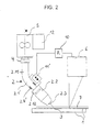
- Fig. 2 illustrated inventive device differs from that in Fig. 1 sketched embodiment with respect to the design of the burner neck 2.1 'integrated movable connection 2.4'.
- the movable connection 2.4 ' is designed as a guide.
- a movable part 2.2 of the burner neck 2.1 'having the gas nozzle 2.2 and the stream nozzle 2.3 is guided telescopically in or on the part 2.11 of the burner neck 2.1' connected to the wire conveying drive 5.
- the guide 2.4 ' is designed so that the movable part 2.12 of the burner neck 2.1' relative to the part 2.11 can not rotate.
- Part 2.11 moving actuator 11 ' may in turn consist of a hydraulic or pneumatic working cylinder, an electromotive linear drive or the like.
- a tactile sensor can also be used in the device according to the invention. This is in the FIGS. 3 to 5 shown.
- the seam guide device has a tactile guide finger 13, which forwards the burner 2 to the contour of the workpiece parts to be joined defined joint 7 scans and is connected to the movable, the burner head bearing section 2.12 of the burner.
- the torch neck 2.1 'integrated joint 2.4 is assigned at least one spring 14, which biases the guide finger 13 frictionally against the joint 7.
- the at least one spring 14 is supported with one of its ends on the part 2:11 of the torch neck mounted on the wire feed drive 5 and with its other end on the part 2:12 of the torch neck 2. 1 'movable by the joint 2.
- the guide finger 13 has an opposite to the workpiece surface obliquely aligned, the workpiece surface contacting portion 13.1, so that the tip of the guide finger 13 is moved during the advancement of the burner 2 in the predetermined feed direction 9 dragging on the workpiece surface along the joint 7.
- Fig. 4 sketched device is different from that in Fig. 3 embodiment shown in the embodiment of integrated in the torch neck movable connection.
- the movable connection is designed as a telescopic guide 2.4 '.
- the guide finger 13 takes over the task of the seam guide sensor according to the FIGS. 1 and 2 while the spring 14 takes over the task of the actuator 11 '.
- the spring 14 presses the lower part 2.12 of the burner neck 2.1 'with the gas nozzle 2.2 and the current nozzle 2.3 and the guide finger 13 in the direction of distance 8 toward the workpiece 1.
- the spring 14 is preferably so formed or arranged, or supplemented by a further spring (not shown), that it also acts laterally in the direction of a workpiece or joining edge 7, so that the guide finger 13 is supported laterally on the workpiece, in particular on the joining edge 7.
- the variants according to the Figures 3 and 4 can be particularly inexpensive, easy and small realize.
- a further actuator 15 is arranged, which causes a corresponding movement of a relative movement between the guide finger 13 and the movable portion of the burner 2 2.12.
- the spring 14 or the at least one movable connection 2.4 is assigned at least one sensor 16, which detects the position and / or the state of tension of the spring 14 or the relative position of the parts 2.11, 2.12 of the movable connection 2.4 and corresponding sensor signals to a controller 10 delivers.
- the controller 10 controls the actuator 15 in response to the sensor signals, so that the flow of the guide finger 13 is compensated.
- FIGS. 1 to 5 illustrated embodiments of flexible lines or hoses (not shown), which are arranged in and / or on the burner neck 2.1 '.
- the embodiment of the invention is not limited to the embodiments described above and shown in the drawing. Rather, a variety of variants are conceivable that even with fundamentally different design of the invention - as stated in the claims - use.
- FIGS. 6 to 12 schematically illustrated devices are each a device for joining workpiece parts by means of an arc.
- the workpiece parts 1 to be joined form a lap joint on which a fillet weld is to be produced.
- the device comprises a scanning finger (guide finger) 13 serving to guide the energy beam along the joint (overlap joint), the tip of which is arranged in front of the guide direction F of the arc.
- the sensing finger 13 may also be referred to as a guide finger or leading tip. It is a tactile probe element, which is moved non-positively along a joint 7 defined by the workpiece parts 1 to be joined and which guides the arc 17 laterally and in the direction of spacing. One can therefore also speak of a tactile seam guide.
- the guide finger 13 of the device according to the invention is formed of electrically insulating material, which has a high wear resistance and a continuous temperature load of at least 400 ° C, preferably at least 500 ° C withstands.
- the electrically insulating material of the guide finger 13 acts insulating with respect to the arc 17 and also insulating with respect to the workpiece parts 1.
- the electrically insulating material of the guide finger 13 is preferably a highly wear-resistant material, for example a highly wear-resistant ceramic material.
- the guide finger 13 may also be formed of an electrically insulating composite material, for example of a material composite comprising a ceramic material. In particular, the insulation may be realized in the form of a ceramic coating of the guide finger 13.
- the guide finger 13 is arranged with respect to the arc so that its tip is arranged with the least possible forward flow in front of the outer edge of the active site W of the arc 17, said lead is not more than 8 mm, preferably not more than 3 mm. In the in the FIGS. 6 to 12 illustrated embodiments the guide finger 13 is preferably arranged so that its tip touches the outer edge of the active site W of the arc 17.
- the guide finger 13 is preferably provided with a heater (not shown).
- the heater is integrated, for example, in the guide finger 13. It may for example consist of a embedded in the guide finger 13 or cast-in heating wire.
- the temperature of the guide finger 13 can also be effected by heat conduction via the receptacle (holder) of the guide finger 13.
- the receptacle (not shown) of the guide finger 13 in this case has a corresponding heating device.
- Another variant of the device according to the invention is to heat the guide finger 13 in a chamber or receptacle (not shown) by heat conduction, heat radiation and / or induction. The thus heated guide finger 13 is then moved out of the chamber for the tactile seam guide. This variant thus provides preheating of the guide finger 13 in the chamber or recording.
- cooling device can be integrated in the guide finger 13 or the guide finger can be mounted on a holder having a cooling device (not shown).
- FIGS. 7 to 10 illustrated embodiment differs from the embodiment of Fig. 6 in that the guide finger 13 is provided with a diaphragm (process diaphragm) 18.
- the diaphragm 18 retains marginal rays of the arc 17, so that the energy input into the workpiece parts 1 in the region of the joint is purposefully reduced (cf. Fig. 8 ). As a result, a reduction in the seam width is achieved.
- the diaphragm 18 is open on one side, namely formed substantially U-shaped. Its open side lies in the guide direction F of the arc 17 viewed at the rear.
- the diaphragm 18 or the guide finger 13 is attached to a holder (not shown) which is connected to the means for supplying the arc 17.
- the diaphragm 18 is thermally conductively connected to the guide finger 13. It is formed from a high temperature resistant material which withstands a continuous temperature load of at least 400 ° C, preferably of at least 500 ° C. Preferably, the diaphragm 18 is formed of a ceramic material or a material composite comprising a ceramic material.
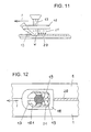
- FIGS. 11 and 12 show a further embodiment of the device according to the invention.
- the guide finger 13 is provided with a means 19 for supplying inert gas, fixed with the guide finger connected is.
- the device 19 for inert gas supply is integrated in the diaphragm.
- the aperture 18 thus serves not only the narrowing of the arc 17 by restraint of marginal rays, but also the targeted supply of inert gas and its holding (concentrating) above the freshly produced weld or joint seam 20.
- the inert gas is in the FIGS. 11 and 12 indicated by arcuate arrows 21.
- the aperture 18 is formed closed, with their energy beam (arc) 17 limiting opening 18.1 is formed substantially oval.
- the opening 18.1 of the panel may optionally also be substantially circular, rectangular or square.
- the device 19 for inert gas supply is formed in this embodiment so that the protective gas ring segment, coaxial and trailing to the energy beam 17 is supplied.
- the device 19 for supplying inert gas in such a way that the protective gas is supplied annularly, coaxially to the energy beam 17.
- the diaphragm so that its opening width can be adjusted. As a result, the energy input or the seam width can be selectively influenced.
- the present invention includes an embodiment in which the shutter is provided with one or more magnetic or electromagnetic Elements is equipped for the targeted influence of the arc. This embodiment also allows a targeted reduction of the seam width.
- the diaphragm may also have a cooling device to increase its continuous temperature capacity.
Landscapes
- Physics & Mathematics (AREA)
- Engineering & Computer Science (AREA)
- Geometry (AREA)
- Plasma & Fusion (AREA)
- Mechanical Engineering (AREA)
- Gas Burners (AREA)
- Arc Welding In General (AREA)
- Manipulator (AREA)
- Butt Welding And Welding Of Specific Article (AREA)
Claims (15)
- Dispositif d'ajout de parties de pièces (1) par l'intermédiaire d'un arc électrique, avec un brûleur, qui présente un col de brûleur (2.1') et une buse à gaz (2.2), le col du brûleur (2.1') étant fixé dans ou à un logement de col de brûleur (4), ou à une poignée ou à un système d'entraînement de fils (5), et avec un dispositif de guidage, caractérisé en ce qu'au moins une liaison mobile (2.4; 2 .4') est intégrée dans le brûleur (2), liaison qui permet un déplacement de la buse à gaz par rapport au logement de col de brûleur (4), à la poignée ou au système d'entraînement de fils (5) et qui est actionnée par le dispositif de guidage en fonction du contour d'un bord d'assemblage (7) défini par les parties de pièce (1) à relier.
- Dispositif selon la revendication 1,
caractérisé en ce que le brûleur (2) possède au moins deux degrés de liberté de par la liaison mobile (2.4; 2.4'). - Dispositif selon la revendication 1 ou 2,
caractérisé en ce que au moins une liaison mobile (2.4; 2.4') est disposée entre une partie (2.11) fixée au logement de col de brûleur (4) et une partie mobile (2.12) du col de brûleur (2.1') par rapport à ladite partie. - Dispositif selon la revendication 1 ou 2,
caractérisé en ce que au moins une liaison mobile (2.4; 2.4') est intégrée entre le col de brûleur (2.1') et la buse à gaz (2.2). - Dispositif selon la revendication 1 ou 2,
caractérisé en ce que le brûleur (2) présente une buse de contact (2.3), au moins une liaison mobile (2.4; 2.4') étant intégrée entre le col de brûleur (2.1') et la buse de contact (2.3). - Dispositif selon la revendication 1 ou 2,
caractérisé en ce que au moins une liaison mobile (2.4; 2.4') est intégrée entre le col de brûleur (2.1') et le logement de col de brûleur (4). - Dispositif selon la revendication 1 ou 2,
caractérisé en ce que au moins une liaison mobile (2.4; 2.4') est intégrée entre le col de brûleur (2.1') et la poignée ou le système d'entraînement de fils (5). - Dispositif selon l'une des revendications 1 à 7,
caractérisé en ce que le dispositif de guidage présente un doigt de guidage (13), qui balaie en aval du brûleur (2) le contour du bord d'assemblage (7) défini par les parties de pièce (1) à relier et qui est relié à une section mobile (2.12) du brûleur portant une tête de brûleur, au moins un ressort (14) étant associé à au moins une liaison mobile (2.4; 2.4'), lequel précontraint par force le doigt de guidage (13) contre le bord d'assemblage (7). - Dispositif selon la revendication 8,
caractérisé en ce qu'au moins un capteur (16) est associé au ressort (14) et/ou à au moins une liaison mobile (2.4; 2.4'), lequel détermine la position et/ou l'état de contrainte du ressort (14) ou la position relative des parties mobiles l'une par rapport à l'autre (2.11, 2.12) de la liaison mobile (2.4; 2.4') et émet les signaux de capteur correspondants, le doigt de guidage (13) étant équipé d'un actionneur (15), qui entraîne un déplacement relatif entre le doigt de guidage (13) et la section mobile (2.12) du brûleur (2), et un régulateur (10) étant associé à l'actionneur (15), qui commande l'actionneur (15) en fonction des signaux de capteur. - Dispositif selon l'une des revendications 1 à 7,
caractérisé en ce que le dispositif de guidage présente un doigt de guidage (13) qui balaie en aval du brûleur (2) le contour du bord d'assemblage (7) défini par les parties de pièce (1) à relier et qui est formé d'un matériau isolant supportant une contrainte de température constante d'au moins 400°C. - Dispositif selon l'une des revendications 8 à 10,
caractérisé en ce que le doigt de guidage (13) est disposé par rapport à l'arc électrique de telle façon que la pointe du doigt de guidage (13) est écartée du bord extérieur du point d'action de l'arc électrique, l'écart ne dépassant pas 8 mm. - Dispositif selon l'une des revendications 8 à 11,
caractérisé en ce que le doigt de guidage (13) est équipé d'un diaphragme (18) qui retient les rayons marginaux de l'arc électrique. - Dispositif selon l'une des revendications 1 à 7,
caractérisé en ce que le dispositif de guidage utilise un fil supplémentaire fondant dans l'arc électrique (17) comme élément palpeur mécanique. - Dispositif selon l'une des revendications 1 à 3,
caractérisé en ce que le dispositif de guidage présente au moins un capteur (6), qui détermine ou balaie la position d'un bord d'assemblage (7) défini par les parties de pièce (1) à relier et émet les signaux de capteur correspondants, au moins un actionneur (11 ') étant associé à au moins une liaison mobile (2.4; 2.4'), au moyen duquel la liaison mobile (2.4; 2.4') peut être actionnée, et un régulateur (10) étant associé à l'actionneur (11 '), qui commande l'actionneur (11 ') en fonction des signaux de capteur. - Dispositif selon la revendication 14,
caractérisé en ce que le régulateur (10) est équipé d'un dispositif, qui compense l'avance du point de mesure du capteur (6) par rapport au point d'action de l'arc électrique pour un capteur (6) précédant l'arc électrique.
Applications Claiming Priority (2)
| Application Number | Priority Date | Filing Date | Title |
|---|---|---|---|
| DE102007006115A DE102007006115A1 (de) | 2007-02-02 | 2007-02-02 | Vorrichtung zum Fügen von Werkstückteilen mittels Lichtbogen mit einer Nahtführungseinrichtung |
| PCT/EP2008/051267 WO2008092953A1 (fr) | 2007-02-02 | 2008-02-01 | Dispositif d'ajout de parties de pièces par l'intermédiaire d'un arc électrique comprenant un dispositif de guidage |
Publications (2)
| Publication Number | Publication Date |
|---|---|
| EP2117760A1 EP2117760A1 (fr) | 2009-11-18 |
| EP2117760B1 true EP2117760B1 (fr) | 2011-05-11 |
Family
ID=39345134
Family Applications (1)
| Application Number | Title | Priority Date | Filing Date |
|---|---|---|---|
| EP08708574A Not-in-force EP2117760B1 (fr) | 2007-02-02 | 2008-02-01 | Dispositif d'ajout de parties de pièces par l'intermédiaire d'un arc électrique comprenant un dispositif de guidage |
Country Status (4)
| Country | Link |
|---|---|
| EP (1) | EP2117760B1 (fr) |
| AT (1) | ATE508831T1 (fr) |
| DE (1) | DE102007006115A1 (fr) |
| WO (1) | WO2008092953A1 (fr) |
Cited By (1)
| Publication number | Priority date | Publication date | Assignee | Title |
|---|---|---|---|---|
| CN108119897A (zh) * | 2017-12-04 | 2018-06-05 | 中国能源建设集团华东电力试验研究院有限公司 | 循环流化床机组的油枪点火系统 |
Families Citing this family (4)
| Publication number | Priority date | Publication date | Assignee | Title |
|---|---|---|---|---|
| FR2979271B1 (fr) * | 2011-08-29 | 2013-08-16 | Peugeot Citroen Automobiles Sa | Controle et reglage de systeme de tete de brasage laser |
| DE102015119424A1 (de) * | 2015-11-11 | 2017-05-11 | Reis Gmbh & Co. Kg Maschinenfabrik | Verfahren zum Bearbeiten zumindest eines Werkstücks |
| CN112222557B (zh) * | 2020-11-02 | 2025-03-21 | 台州市圣西亚金刚石设备有限公司 | 钎焊装置的焊带头部位置校正装置 |
| US12017295B2 (en) | 2021-02-10 | 2024-06-25 | The Esab Group Inc. | Torch with adjustable features |
Family Cites Families (15)
| Publication number | Priority date | Publication date | Assignee | Title |
|---|---|---|---|---|
| CH625148A5 (fr) * | 1978-07-25 | 1981-09-15 | Roberto Torrani | |
| GB2112961B (en) * | 1982-01-04 | 1985-12-18 | Hitachi Ltd | Corner angle portion detecting apparatus |
| EP0118439B1 (fr) * | 1982-09-07 | 1987-08-19 | Caterpillar Inc. | Systeme de soudage adaptatif |
| DE3341964A1 (de) | 1983-11-21 | 1985-05-30 | Brose Werkzeugmaschinen GmbH & Co KG, 6625 Püttlingen | Vorrichtung zur automatischen fuehrung von werkzeugen |
| DD247625A1 (de) | 1986-03-27 | 1987-07-15 | Zentralinstitut Schweiss | Verfahren zur zweidimensionalen schweissbrennerfuehrung bei v- und ueberlappnaehten |
| US5015821A (en) * | 1988-02-15 | 1991-05-14 | Amada Company, Limited | Computer controlled welding robot |
| US5018705A (en) * | 1990-05-29 | 1991-05-28 | Caterpillar Inc. | Break away torch holder for cutting machines |
| DE19615069A1 (de) | 1996-04-17 | 1997-10-23 | Hannover Laser Zentrum | Verfahren und Vorrichtung zum Nachführen von Werkzeugen mittels Kantenverfolgung |
| JP2791400B2 (ja) * | 1996-07-30 | 1998-08-27 | 川崎重工業株式会社 | 消耗電極式のアーク溶接方法及びアーク溶接装置 |
| JP3385332B2 (ja) * | 1997-01-27 | 2003-03-10 | 日鐵住金溶接工業株式会社 | 2電極片面ガスシールドアーク溶接方法 |
| DE10002230A1 (de) | 2000-01-20 | 2001-07-26 | Msc Mes Sensor Und Computertec | Verfahren und Vorrichtung zur adaptiven Roboterführung |
| DE10006852C5 (de) | 2000-02-16 | 2004-08-26 | Anders, Michael, Dr.-Ing. | Verfahren und Vorrichtung zum Fügen von Werkstückteilen mittels eines Energiestrahls, insbesondere Laserstrahls |
| AT412765B (de) * | 2003-07-03 | 2005-07-25 | Fronius Int Gmbh | Schweissbrenner |
| EP2056989B1 (fr) * | 2006-08-30 | 2015-01-28 | Abb Ag | Col flexible de soudeuse et appareil de soudure destiné à un dispositif de manipulation |
| DE102006056252B4 (de) | 2006-09-26 | 2009-06-10 | Scansonic Mi Gmbh | Vorrichtung zur Führung eines Energiestrahls |
-
2007
- 2007-02-02 DE DE102007006115A patent/DE102007006115A1/de not_active Withdrawn
-
2008
- 2008-02-01 AT AT08708574T patent/ATE508831T1/de active
- 2008-02-01 EP EP08708574A patent/EP2117760B1/fr not_active Not-in-force
- 2008-02-01 WO PCT/EP2008/051267 patent/WO2008092953A1/fr not_active Ceased
Cited By (1)
| Publication number | Priority date | Publication date | Assignee | Title |
|---|---|---|---|---|
| CN108119897A (zh) * | 2017-12-04 | 2018-06-05 | 中国能源建设集团华东电力试验研究院有限公司 | 循环流化床机组的油枪点火系统 |
Also Published As
| Publication number | Publication date |
|---|---|
| EP2117760A1 (fr) | 2009-11-18 |
| WO2008092953A1 (fr) | 2008-08-07 |
| ATE508831T1 (de) | 2011-05-15 |
| DE102007006115A1 (de) | 2008-08-14 |
Similar Documents
| Publication | Publication Date | Title |
|---|---|---|
| EP2117760B1 (fr) | Dispositif d'ajout de parties de pièces par l'intermédiaire d'un arc électrique comprenant un dispositif de guidage | |
| EP3010679B1 (fr) | Dispositif d'usinage avec un element presseur situe avant ou apres un autre element presseur situe pres d'un faisceau | |
| DE102007006114B4 (de) | Verfahren zur Regelung der Vorschubgeschwindigkeit eines Drahtes und Vorrichtung zum Zuführen von Draht in einem thermischen Fügeprozeß | |
| DE102012102463A1 (de) | Punktschweißvorrichtung und Punktschweißverfahren | |
| DE102013104548B3 (de) | Fügevorrichtung und Fügeverfahren zum thermischen Fügen | |
| WO2008037548A1 (fr) | Dispositif de guidage d'un faisceau d'énergie | |
| EP2641704A1 (fr) | Appareil de robot avec dispositif de détection destiné à la manutention, au montage et/ou au traitement de pièces à usiner | |
| DE202017006112U1 (de) | Vorrichtung zum nahezu verzögerungsfreien Ändern der Schweißrichtung der einer Anlage zum Rührreibschweißen wenn die geometrische Anordnung der zu verschweißenden Fügepartner oder Materialunebenheiten dies erfordern | |
| EP3924132B1 (fr) | Dispositif d'avance de fil métallique et procédé pour induire une avance de fil métallique | |
| EP3017901A1 (fr) | Chalumeau de soudure par gaz inerte de tungstene avec un guidage en forme d'arc | |
| DE20306581U1 (de) | Laserschweißanordnung | |
| EP2173513B1 (fr) | Dispositif de soudage doté d'un système mécanique de suivi du cordon | |
| DE1515160C3 (de) | Lichtbogenschweißmaschine mit Kantentaster zum Verschweißen überlappter Bleche | |
| EP3424636B1 (fr) | Système de soudage laser comprenant un dispositif pousseur, une optique d'usinage et au moins un dispositif de guidage tactile | |
| DE102006062323B4 (de) | Vorrichtung zum Fügen von Werkstückteilen mit Tastfinger aus elektrisch isolierendem Material | |
| EP2735394B1 (fr) | Tête de soudage d'une installation de soudage sous poudre et installation de soudage sous poudre dotée d'une telle tête de soudage | |
| DE10304709B4 (de) | Verfahren und Vorrichtung zum Laser-Hybridschweißen | |
| DE10151828B4 (de) | Vorrichtung und Verfahren zum Laserstrahllöten, insbesondere Laserstrahlhartlöten | |
| DE20112510U1 (de) | Schweißeinrichtung | |
| EP3067144B1 (fr) | Dispositif de soudage comprenant un dispositif de couplage de moteur | |
| DE102015003084A1 (de) | Schweißvorrichtung mit vorteilhaftem Fahrwerk | |
| DE102015220889B4 (de) | Verfahren und Vorrichtung zum Schweißen von Teilen | |
| DE10162452A1 (de) | Verfahren zur Herstellung einer Schweißnaht | |
| DE102009003297A1 (de) | Fügevorrichtung für ein stoffschlüssiges Fügen | |
| DE29910028U1 (de) | Programmierspitze |
Legal Events
| Date | Code | Title | Description |
|---|---|---|---|
| PUAI | Public reference made under article 153(3) epc to a published international application that has entered the european phase |
Free format text: ORIGINAL CODE: 0009012 |
|
| 17P | Request for examination filed |
Effective date: 20090902 |
|
| AK | Designated contracting states |
Kind code of ref document: A1 Designated state(s): AT BE BG CH CY CZ DE DK EE ES FI FR GB GR HR HU IE IS IT LI LT LU LV MC MT NL NO PL PT RO SE SI SK TR |
|
| DAX | Request for extension of the european patent (deleted) | ||
| GRAP | Despatch of communication of intention to grant a patent |
Free format text: ORIGINAL CODE: EPIDOSNIGR1 |
|
| GRAS | Grant fee paid |
Free format text: ORIGINAL CODE: EPIDOSNIGR3 |
|
| GRAA | (expected) grant |
Free format text: ORIGINAL CODE: 0009210 |
|
| AK | Designated contracting states |
Kind code of ref document: B1 Designated state(s): AT BE BG CH CY CZ DE DK EE ES FI FR GB GR HR HU IE IS IT LI LT LU LV MC MT NL NO PL PT RO SE SI SK TR |
|
| REG | Reference to a national code |
Ref country code: GB Ref legal event code: FG4D Free format text: NOT ENGLISH |
|
| REG | Reference to a national code |
Ref country code: CH Ref legal event code: EP |
|
| REG | Reference to a national code |
Ref country code: IE Ref legal event code: FG4D |
|
| REG | Reference to a national code |
Ref country code: DE Ref legal event code: R096 Ref document number: 502008003489 Country of ref document: DE Effective date: 20110622 |
|
| REG | Reference to a national code |
Ref country code: NL Ref legal event code: VDEP Effective date: 20110511 |
|
| PG25 | Lapsed in a contracting state [announced via postgrant information from national office to epo] |
Ref country code: NO Free format text: LAPSE BECAUSE OF FAILURE TO SUBMIT A TRANSLATION OF THE DESCRIPTION OR TO PAY THE FEE WITHIN THE PRESCRIBED TIME-LIMIT Effective date: 20110811 Ref country code: SE Free format text: LAPSE BECAUSE OF FAILURE TO SUBMIT A TRANSLATION OF THE DESCRIPTION OR TO PAY THE FEE WITHIN THE PRESCRIBED TIME-LIMIT Effective date: 20110511 Ref country code: PT Free format text: LAPSE BECAUSE OF FAILURE TO SUBMIT A TRANSLATION OF THE DESCRIPTION OR TO PAY THE FEE WITHIN THE PRESCRIBED TIME-LIMIT Effective date: 20110912 Ref country code: LT Free format text: LAPSE BECAUSE OF FAILURE TO SUBMIT A TRANSLATION OF THE DESCRIPTION OR TO PAY THE FEE WITHIN THE PRESCRIBED TIME-LIMIT Effective date: 20110511 |
|
| PG25 | Lapsed in a contracting state [announced via postgrant information from national office to epo] |
Ref country code: FI Free format text: LAPSE BECAUSE OF FAILURE TO SUBMIT A TRANSLATION OF THE DESCRIPTION OR TO PAY THE FEE WITHIN THE PRESCRIBED TIME-LIMIT Effective date: 20110511 Ref country code: IS Free format text: LAPSE BECAUSE OF FAILURE TO SUBMIT A TRANSLATION OF THE DESCRIPTION OR TO PAY THE FEE WITHIN THE PRESCRIBED TIME-LIMIT Effective date: 20110911 Ref country code: ES Free format text: LAPSE BECAUSE OF FAILURE TO SUBMIT A TRANSLATION OF THE DESCRIPTION OR TO PAY THE FEE WITHIN THE PRESCRIBED TIME-LIMIT Effective date: 20110822 Ref country code: SI Free format text: LAPSE BECAUSE OF FAILURE TO SUBMIT A TRANSLATION OF THE DESCRIPTION OR TO PAY THE FEE WITHIN THE PRESCRIBED TIME-LIMIT Effective date: 20110511 Ref country code: GR Free format text: LAPSE BECAUSE OF FAILURE TO SUBMIT A TRANSLATION OF THE DESCRIPTION OR TO PAY THE FEE WITHIN THE PRESCRIBED TIME-LIMIT Effective date: 20110812 Ref country code: LV Free format text: LAPSE BECAUSE OF FAILURE TO SUBMIT A TRANSLATION OF THE DESCRIPTION OR TO PAY THE FEE WITHIN THE PRESCRIBED TIME-LIMIT Effective date: 20110511 Ref country code: CY Free format text: LAPSE BECAUSE OF FAILURE TO SUBMIT A TRANSLATION OF THE DESCRIPTION OR TO PAY THE FEE WITHIN THE PRESCRIBED TIME-LIMIT Effective date: 20110511 |
|
| REG | Reference to a national code |
Ref country code: IE Ref legal event code: FD4D |
|
| PG25 | Lapsed in a contracting state [announced via postgrant information from national office to epo] |
Ref country code: NL Free format text: LAPSE BECAUSE OF FAILURE TO SUBMIT A TRANSLATION OF THE DESCRIPTION OR TO PAY THE FEE WITHIN THE PRESCRIBED TIME-LIMIT Effective date: 20110511 |
|
| PG25 | Lapsed in a contracting state [announced via postgrant information from national office to epo] |
Ref country code: CZ Free format text: LAPSE BECAUSE OF FAILURE TO SUBMIT A TRANSLATION OF THE DESCRIPTION OR TO PAY THE FEE WITHIN THE PRESCRIBED TIME-LIMIT Effective date: 20110511 Ref country code: IE Free format text: LAPSE BECAUSE OF FAILURE TO SUBMIT A TRANSLATION OF THE DESCRIPTION OR TO PAY THE FEE WITHIN THE PRESCRIBED TIME-LIMIT Effective date: 20110511 Ref country code: EE Free format text: LAPSE BECAUSE OF FAILURE TO SUBMIT A TRANSLATION OF THE DESCRIPTION OR TO PAY THE FEE WITHIN THE PRESCRIBED TIME-LIMIT Effective date: 20110511 |
|
| PG25 | Lapsed in a contracting state [announced via postgrant information from national office to epo] |
Ref country code: SK Free format text: LAPSE BECAUSE OF FAILURE TO SUBMIT A TRANSLATION OF THE DESCRIPTION OR TO PAY THE FEE WITHIN THE PRESCRIBED TIME-LIMIT Effective date: 20110511 Ref country code: RO Free format text: LAPSE BECAUSE OF FAILURE TO SUBMIT A TRANSLATION OF THE DESCRIPTION OR TO PAY THE FEE WITHIN THE PRESCRIBED TIME-LIMIT Effective date: 20110511 Ref country code: PL Free format text: LAPSE BECAUSE OF FAILURE TO SUBMIT A TRANSLATION OF THE DESCRIPTION OR TO PAY THE FEE WITHIN THE PRESCRIBED TIME-LIMIT Effective date: 20110511 Ref country code: DK Free format text: LAPSE BECAUSE OF FAILURE TO SUBMIT A TRANSLATION OF THE DESCRIPTION OR TO PAY THE FEE WITHIN THE PRESCRIBED TIME-LIMIT Effective date: 20110511 |
|
| PLBE | No opposition filed within time limit |
Free format text: ORIGINAL CODE: 0009261 |
|
| STAA | Information on the status of an ep patent application or granted ep patent |
Free format text: STATUS: NO OPPOSITION FILED WITHIN TIME LIMIT |
|
| 26N | No opposition filed |
Effective date: 20120214 |
|
| PG25 | Lapsed in a contracting state [announced via postgrant information from national office to epo] |
Ref country code: IT Free format text: LAPSE BECAUSE OF FAILURE TO SUBMIT A TRANSLATION OF THE DESCRIPTION OR TO PAY THE FEE WITHIN THE PRESCRIBED TIME-LIMIT Effective date: 20110511 Ref country code: HR Free format text: LAPSE BECAUSE OF FAILURE TO SUBMIT A TRANSLATION OF THE DESCRIPTION OR TO PAY THE FEE WITHIN THE PRESCRIBED TIME-LIMIT Effective date: 20111123 |
|
| REG | Reference to a national code |
Ref country code: DE Ref legal event code: R097 Ref document number: 502008003489 Country of ref document: DE Effective date: 20120214 |
|
| BERE | Be: lapsed |
Owner name: SCANSONIC MI G.M.B.H. Effective date: 20120228 |
|
| PG25 | Lapsed in a contracting state [announced via postgrant information from national office to epo] |
Ref country code: MC Free format text: LAPSE BECAUSE OF NON-PAYMENT OF DUE FEES Effective date: 20120229 |
|
| REG | Reference to a national code |
Ref country code: CH Ref legal event code: PL |
|
| GBPC | Gb: european patent ceased through non-payment of renewal fee |
Effective date: 20120201 |
|
| PG25 | Lapsed in a contracting state [announced via postgrant information from national office to epo] |
Ref country code: CH Free format text: LAPSE BECAUSE OF NON-PAYMENT OF DUE FEES Effective date: 20120229 Ref country code: LI Free format text: LAPSE BECAUSE OF NON-PAYMENT OF DUE FEES Effective date: 20120229 |
|
| REG | Reference to a national code |
Ref country code: FR Ref legal event code: ST Effective date: 20121031 |
|
| PG25 | Lapsed in a contracting state [announced via postgrant information from national office to epo] |
Ref country code: BE Free format text: LAPSE BECAUSE OF NON-PAYMENT OF DUE FEES Effective date: 20120228 |
|
| PG25 | Lapsed in a contracting state [announced via postgrant information from national office to epo] |
Ref country code: FR Free format text: LAPSE BECAUSE OF NON-PAYMENT OF DUE FEES Effective date: 20120229 Ref country code: GB Free format text: LAPSE BECAUSE OF NON-PAYMENT OF DUE FEES Effective date: 20120201 |
|
| PG25 | Lapsed in a contracting state [announced via postgrant information from national office to epo] |
Ref country code: BG Free format text: LAPSE BECAUSE OF FAILURE TO SUBMIT A TRANSLATION OF THE DESCRIPTION OR TO PAY THE FEE WITHIN THE PRESCRIBED TIME-LIMIT Effective date: 20110811 |
|
| PG25 | Lapsed in a contracting state [announced via postgrant information from national office to epo] |
Ref country code: MT Free format text: LAPSE BECAUSE OF FAILURE TO SUBMIT A TRANSLATION OF THE DESCRIPTION OR TO PAY THE FEE WITHIN THE PRESCRIBED TIME-LIMIT Effective date: 20110511 |
|
| PG25 | Lapsed in a contracting state [announced via postgrant information from national office to epo] |
Ref country code: HR Free format text: LAPSE BECAUSE OF FAILURE TO SUBMIT A TRANSLATION OF THE DESCRIPTION OR TO PAY THE FEE WITHIN THE PRESCRIBED TIME-LIMIT Effective date: 20110511 |
|
| PG25 | Lapsed in a contracting state [announced via postgrant information from national office to epo] |
Ref country code: TR Free format text: LAPSE BECAUSE OF FAILURE TO SUBMIT A TRANSLATION OF THE DESCRIPTION OR TO PAY THE FEE WITHIN THE PRESCRIBED TIME-LIMIT Effective date: 20110511 |
|
| PG25 | Lapsed in a contracting state [announced via postgrant information from national office to epo] |
Ref country code: LU Free format text: LAPSE BECAUSE OF NON-PAYMENT OF DUE FEES Effective date: 20120201 |
|
| PG25 | Lapsed in a contracting state [announced via postgrant information from national office to epo] |
Ref country code: HU Free format text: LAPSE BECAUSE OF FAILURE TO SUBMIT A TRANSLATION OF THE DESCRIPTION OR TO PAY THE FEE WITHIN THE PRESCRIBED TIME-LIMIT Effective date: 20080201 |
|
| PGFP | Annual fee paid to national office [announced via postgrant information from national office to epo] |
Ref country code: AT Payment date: 20200218 Year of fee payment: 13 Ref country code: DE Payment date: 20200229 Year of fee payment: 13 |
|
| REG | Reference to a national code |
Ref country code: DE Ref legal event code: R119 Ref document number: 502008003489 Country of ref document: DE |
|
| REG | Reference to a national code |
Ref country code: AT Ref legal event code: MM01 Ref document number: 508831 Country of ref document: AT Kind code of ref document: T Effective date: 20210201 |
|
| PG25 | Lapsed in a contracting state [announced via postgrant information from national office to epo] |
Ref country code: AT Free format text: LAPSE BECAUSE OF NON-PAYMENT OF DUE FEES Effective date: 20210201 |
|
| PG25 | Lapsed in a contracting state [announced via postgrant information from national office to epo] |
Ref country code: DE Free format text: LAPSE BECAUSE OF NON-PAYMENT OF DUE FEES Effective date: 20210901 |