EP2117768B1 - Betätigungsvorrichtung für drehmaschine, insbesondere für vertikalrevolverdrehmaschinen und drehmaschine mit dieser vorrichtung - Google Patents
Betätigungsvorrichtung für drehmaschine, insbesondere für vertikalrevolverdrehmaschinen und drehmaschine mit dieser vorrichtung Download PDFInfo
- Publication number
- EP2117768B1 EP2117768B1 EP08717333A EP08717333A EP2117768B1 EP 2117768 B1 EP2117768 B1 EP 2117768B1 EP 08717333 A EP08717333 A EP 08717333A EP 08717333 A EP08717333 A EP 08717333A EP 2117768 B1 EP2117768 B1 EP 2117768B1
- Authority
- EP
- European Patent Office
- Prior art keywords
- saddle
- lathe
- workpiece
- manipulator
- machined
- Prior art date
- Legal status (The legal status is an assumption and is not a legal conclusion. Google has not performed a legal analysis and makes no representation as to the accuracy of the status listed.)
- Active
Links
- 230000033001 locomotion Effects 0.000 claims abstract description 23
- 238000006073 displacement reaction Methods 0.000 claims abstract description 6
- 238000003754 machining Methods 0.000 claims abstract description 5
- 230000005540 biological transmission Effects 0.000 description 1
- 210000000080 chela (arthropods) Anatomy 0.000 description 1
- 238000006243 chemical reaction Methods 0.000 description 1
- 230000002939 deleterious effect Effects 0.000 description 1
- 230000000694 effects Effects 0.000 description 1
- 230000002452 interceptive effect Effects 0.000 description 1
- 238000004519 manufacturing process Methods 0.000 description 1
- 230000003134 recirculating effect Effects 0.000 description 1
- 230000000630 rising effect Effects 0.000 description 1
Images


Classifications
-
- B—PERFORMING OPERATIONS; TRANSPORTING
- B23—MACHINE TOOLS; METAL-WORKING NOT OTHERWISE PROVIDED FOR
- B23Q—DETAILS, COMPONENTS, OR ACCESSORIES FOR MACHINE TOOLS, e.g. ARRANGEMENTS FOR COPYING OR CONTROLLING; MACHINE TOOLS IN GENERAL CHARACTERISED BY THE CONSTRUCTION OF PARTICULAR DETAILS OR COMPONENTS; COMBINATIONS OR ASSOCIATIONS OF METAL-WORKING MACHINES, NOT DIRECTED TO A PARTICULAR RESULT
- B23Q7/00—Arrangements for handling work specially combined with or arranged in, or specially adapted for use in connection with, machine tools, e.g. for conveying, loading, positioning, discharging, sorting
- B23Q7/04—Arrangements for handling work specially combined with or arranged in, or specially adapted for use in connection with, machine tools, e.g. for conveying, loading, positioning, discharging, sorting by means of grippers
- B23Q7/045—Arrangements for handling work specially combined with or arranged in, or specially adapted for use in connection with, machine tools, e.g. for conveying, loading, positioning, discharging, sorting by means of grippers using a tool holder as a work-transporting gripper
Definitions
- the present invention concerns a lathe, in particular a vertical turret lathe, having the characteristics mentioned in the preamble of main claim 1.
- the invention finds a particular, although not exclusive, application in the field of vertical turret lathes in which the workpiece to be machined is disposed on a table or chuck rotating about a vertical axis, and wherein the toolholder saddle or carriage is slidably mounted on a horizontal guide or traverse also capable of vertical raising/lowering movements with respect to the chuck.
- manipulating devices provided on the toolholder saddle, in particular comprising a pair of workpiece gripping devices respectively mounted on one or the other of the opposed lateral sides of the toolholder saddle.
- the gripping devices provide for the loading of the workpieces to be machined and the unloading of the machined workpieces, by means of the movement of the toolholder saddle along the horizontal guide.
- a preferred configuration provides that a workpiece loading station and a workpiece unloading station are respectively positioned on the lathe on laterally opposed sides.
- the saddle when the machining of a workpiece is completed, the saddle can be displaced into a position in which one gripping device is located at the loading station to take up a workpiece to be machined, and the other gripping device is located in axis on the chuck to take up the workpiece just machined.
- a subsequent movement of the saddle along the guide brings it into a second position in which the device with the workpiece to be machined is at the chuck and the device with the machined workpiece is at the unloading station.
- the lathe itself by means of the movement of the toolholder saddle, undertakes the loading and unloading of the workpieces.
- a technical solution of the aforesaid type if the loading and unloading stations provide workpiece conveyors equipped with mechanical stops for arresting the workpiece, in particular at the loading station, in a predetermined position so as to be grasped correctly by the gripping device, has certain limitations.
- the arrival at the loading station of workpieces to be machined having different dimensions requires a different, corresponding positioning of the mechanical stop necessary to compensate the dimensional differences of the workpieces and to allow the manipulator, with the same horizontal travel of the saddle, to position itself in axis with the workpiece in order to grasp it correctly.
- the problem underlying the present invention is that of providing a manipulating device for lathes and a lathe including such a device which are structurally and functionally designed so as to make it possible to remedy the limitations mentioned with reference to the prior art cited.
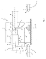
- the reference 1 indicates as a whole a manipulating device, produced according to the invention, and designed to be fitted to a lathe 2 with vertical turret 3.
- the lathe 2 shown only diagrammatically, comprises a workpiece-holding chuck 4 rotating about a main axis Z, and arranged to rotate the workpiece during machining.
- the lathe 2 further comprises a guide or traverse 5 extending axially in a direction X, directed perpendicularly to the axis Z, and on which one or more tool holder saddles are guided parallel to the direction X.
- the lathe For the transfer of the workpieces to be machined, indicated by P in the drawings, to and from the lathe, the lathe is associated with a loading station C for the workpieces P to be machined and with a separate unloading station S for the machined workpieces, the stations being disposed on laterally opposed sides of the lathe and suitably spaced therefrom.
- Each loading and unloading station is conveniently provided with a respective conveyor belt for respectively feeding the workpieces P to be machined to the lathe and for unloading the machined workpieces and removing them from the work area.
- the reference 8 indicates the conveyor belt to the loading station C, while 9 indicates a similar belt located in the unloading station S.
- the chuck 4 is positioned at predetermined distances from the belts, preferably in an intermediate position between them.
- the manipulating device 1 comprises a first and a second manipulator, indicated respectively by 10 and 11, each of which comprises a respective gripping device 10a, 11a, provided for example in the form of a pincer or another similar item of equipment for gripping and manipulating the workpiece P.
- Each manipulator 10, 11 is in addition rigidly connected to a respective, different saddle 12,13, both the saddles being slidably mounted on the guide 5 so as to be displaceable in the direction X with respective movements independent of one another.
- each saddle 12, 13 may be controlled by separate, different entraining means, for example of the type including recirculating ball screws, or other similar systems for transmission and conversion of the motion.
- One or both of the saddles 12, 13 may be equipped with one or more tools U, shown only diagrammatically in the drawings, and suitable for carrying out the preselected machining operations for the workpiece P.
- a mechanical stop member 15 is provided which, by interfering with the travel of the workpiece P along the belt, functions as a stroke limiter for arresting the workpiece P in a preselected position relative to the belt.
- This positioning is selected to permit the manipulator 10 to position itself, in its travel along X', coaxially with the workpiece P to be picked up on the belt. Provision is made for this positioning to take place in one of the end positions of the travel of the manipulator along X'. In this position, a vertical movement of the manipulator 10 parallel to the axis Z causes the gripping device 10a to grasp the workpiece P on the belt 8.
- the reference 16 indicates a further mechanical stop member capable of being associated with the unloading belt 9 in a manner entirely similar to that provided for in the belt 8 described above.
- the references P' and P" designate workpieces to be machined, for example having axial symmetry, and which have different diameters, indicated respectively by d' and d". Due to the effect of the positioning of the stop member 15, the workpieces P' and P" are therefore out of axis with each other.
- the manipulator 10 in order to be brought into axis with the workpieces, must execute different strokes in the direction X'.
- the manipulator is required to execute a further stroke, indicated by L (equal to the interaxial distance between the workpieces P' and P") to bring itself into a position coaxial with the workpiece P'.
- the supplementary stroke L may be executed only by the saddle 12, no displacement of the saddle 13 being required. All this makes it possible to compensate the dimensional differences of the workpieces P arriving on the belt 8, without requiring any repositioning of the stop member 15, it being simply necessary to regulate the distance D between the manipulators,' which may be previously programmed according to the type of workpieces to be machined, fed to the loading station.
- the manipulator 10 is displaceable along an axis Z' directed parallel to the direction Z, and for the manipulator 11 to be displaceable along a corresponding axis Z", also parallel to the axis Z.
- the movements along said additional axes may conveniently be provided to be independent of one another. In this case they may be obtained by means of independent movements of the respective saddles 12, 13 to which the corresponding manipulators are rigidly connected.
- each manipulator 10, 11 it is possible to provide for each manipulator 10, 11 to be capable of a relative movement, along the respective axis Z', Z", relative to its own corresponding saddle 12, 13.
- Figure 4 illustrates a configuration of the device of the invention different from that of Figure 1 , in which the saddle 13 is arranged for left-hand mounting (viewing the drawing) with respect to the toolholder saddle 12, unlike in Figure 1 , in which the right-hand mounting of the saddle 13 is shown.
- the saddle 13 may be produced so that it can be mounted on the right or on the left relative to the saddle 12, with suitable linking of the manipulators 10, 11 to the respective saddles.
- With left-hand mounting it is possible to compensate the dimensional differences of the workpieces P, by means of an additional stroke of the saddle 12, independently of the working stroke of the toolholder saddle 13, this latter not therefore being influenced, in its working stroke, by the arrival at the loading station C of dimensionally different workpieces.
- the manipulating device 1 In operation, provision is made for the manipulating device 1 to be displaceable between a first and a second operating state shown respectively by solid lines and by dashed lines in Figure 3 .
- the manipulating device In the first state the manipulating device is positioned with the manipulator device 10 at the belt 8, where it is located in axis with a workpiece P to be machined, and with the manipulator device 11 located in axis with the chuck in which a machined workpiece P is locked.
- the manipulator device 11 With corresponding vertical movements for lowering of the manipulators 10, 11, the workpiece P to be machined is grasped by the manipulator 10 and the machined workpiece P is grasped by the manipulator 11.
- the manipulators With a subsequent vertical raising followed by a horizontal movement of the saddles 12, 13, the manipulators are brought into the second operating state (dashed lines in the drawing), in which the manipulator device 10 is brought into axis with the chuck 4 and the device 11 is brought to the unloading belt in order to deposit the machined workpiece on the belt itself.
- a vertical lowering movement of the manipulators completes the step in which the workpiece P to be machined is positioned by the manipulator 10 on the chuck and the machined workpiece is moved by the manipulator 11 onto the unloading belt.
- the invention thus solves the problem posed, providing the advantages mentioned above compared with the known solutions.
Landscapes
- Engineering & Computer Science (AREA)
- Mechanical Engineering (AREA)
- Turning (AREA)
- Machine Tool Units (AREA)
- Auxiliary Devices For Machine Tools (AREA)
- Finish Polishing, Edge Sharpening, And Grinding By Specific Grinding Devices (AREA)
Claims (8)
- Drehmaschine, insbesondere Vertikalrevolverdrehmaschine mit mindestens einem Werkzeughalterschlitten, des Typs, der mindestens eine erste und eine zweite Werkstückmanipulatorvorrichtung (10, 11) umfasst, die dem Schlitten derart zugeordnet sind, dass mittels der Verschiebung des Werkzeughalterschlittens die Manipulatorvorrichtungen (10, 11) zwischen einer Station (C) zum Beladen mit zu bearbeitenden Werkstücken (P) und einer Station (S) zum Entladen von bearbeiteten Werkstücken bewegbar sind, wobei ein Werkstücktisch (4) der Drehmaschine zwischen die Stationen (C, S) so platziert ist, dass das Werkstück (P) während eines Bearbeitens auf der Drehmaschine gelagert ist, dadurch gekennzeichnet, dass die erste und zweite Manipulatorvorrichtung (10, 11) mit voneinander unabhängigen Bewegungen mindestens in der Bewegungsrichtung (X) des Werkzeughalterschlittens zu und von der Belade- (C) und Entladestation (S) und dem Werkstücktisch (4) in der Weise bewegbar sind, dass der Abstand zwischen den Manipulatorvorrichtungen (10, 11) auf der Drehmaschine mindestens in der Richtung (X) einstellbar ist.
- Drehmaschine nach Anspruch 1, wobei die Vorrichtungen (10, 11) mit voneinander unabhängigen Bewegungen in eine erste Richtung (X', X") im Wesentlichen senkrecht zur Rotationsachse (Z) des der Drehmaschine zugeordneten Werkstücktischs (4) bewegbar sind.
- Drehmaschine nach Anspruch 2, wobei die erste und zweite Manipulatorvorrichtung (10, 11) dazu ausgebildet sind, dass sie auf zugehörige unterschiedliche Schlitten (12, 13) anzubringen sind, die mit voneinander unabhängigen Bewegungen mindestens in die erste Richtung (X', X") gesteuert werden.
- Drehmaschine nach Anspruch 3, wobei die erste und zweite Manipulatorvorrichtung (10, 11) unabhängig voneinander in eine weitere, zweite Richtung (Z', Z") senkrecht zu der ersten Richtung bewegbar sind.
- Drehmaschine nach Anspruch 4, wobei die zweite Richtung (Z', Z") zur Rotationsachse (Z) des Werkstücktischs (4) parallel ist.
- Drehmaschine nach Anspruch 4 oder 5, wobei die Schlitten (12, 13) mit voneinander unabhängigen Bewegungen parallel zu der zweiten Richtung (Z', Z") bewegbar sind, wobei jede der Manipulatorvorrichtungen (10, 11) mit dem zugehörigen Schlitten (12, 13) starr verbunden ist.
- Drehmaschine nach Anspruch 4 oder 5, wobei jede der Manipulatorvorrichtungen (10, 11) dazu ausgebildet ist, dass sie relativ zu ihrem eigenen zugehörigen Schlitten (12, 13) parallel zu der zweiten Richtung bewegbar ist.
- Drehmaschine nach einem der vorhergehenden Ansprüche, umfassend mindestens einen Werkzeughalterschlitten und ein drehbares Werkstückhalter-Spannfutter, wobei der mindestens eine Schlitten so ausgebildet ist, dass er zwischen einer Station (C) zum Beladen mit zu bearbeitenden Werkstücken (P) und einer Station (S) zum Entladen von bearbeiteten Werkstücken bewegbar ist, wobei ein Werkstücktisch (4) zwischen die Stationen (C, S) so platziert ist, dass der Werkzeughalterschlitten mit den Manipulatorvorrichtungen (10, 11) versehen ist.
Applications Claiming Priority (2)
| Application Number | Priority Date | Filing Date | Title |
|---|---|---|---|
| IT000077A ITPD20070077A1 (it) | 2007-03-07 | 2007-03-07 | Dispositivo manipolatore per torni, in particolare per torni a torretta verticale e tornio includente detto dispositivo |
| PCT/EP2008/052570 WO2008107420A1 (en) | 2007-03-07 | 2008-03-03 | Manipulating device for lathes, in particular for vertical turret lathes, and a lathe including said device |
Publications (2)
| Publication Number | Publication Date |
|---|---|
| EP2117768A1 EP2117768A1 (de) | 2009-11-18 |
| EP2117768B1 true EP2117768B1 (de) | 2010-11-03 |
Family
ID=39386476
Family Applications (1)
| Application Number | Title | Priority Date | Filing Date |
|---|---|---|---|
| EP08717333A Active EP2117768B1 (de) | 2007-03-07 | 2008-03-03 | Betätigungsvorrichtung für drehmaschine, insbesondere für vertikalrevolverdrehmaschinen und drehmaschine mit dieser vorrichtung |
Country Status (5)
| Country | Link |
|---|---|
| EP (1) | EP2117768B1 (de) |
| AT (1) | ATE486687T1 (de) |
| DE (1) | DE602008003310D1 (de) |
| IT (1) | ITPD20070077A1 (de) |
| WO (1) | WO2008107420A1 (de) |
Families Citing this family (2)
| Publication number | Priority date | Publication date | Assignee | Title |
|---|---|---|---|---|
| ITMO20110231A1 (it) * | 2011-09-15 | 2013-03-16 | Denver Spa | Centro di taglio a controllo numerico per tagliare materiale in lastra, in particolare vetro e/o pietra |
| ITVI20110345A1 (it) * | 2011-12-30 | 2013-07-01 | Donatoni Macchine S R L | Unita' di taglio per lastre in materiale lapideo |
Family Cites Families (4)
| Publication number | Priority date | Publication date | Assignee | Title |
|---|---|---|---|---|
| US3910423A (en) * | 1974-10-10 | 1975-10-07 | Aspro Inc | Spinner loader equipment |
| DE3206547A1 (de) * | 1982-02-24 | 1983-09-01 | J. E. Reinecker Maschinenbau GmbH & Co KG, 7900 Ulm | Schleifmaschine mit einem steuerbaren werkstueckhandhabungssystem |
| IT1253293B (it) | 1991-10-31 | 1995-07-14 | Minganti Spa | Tornio verticale, predisposto per provvedere in forma autonoma, semplificata ed economica, al carico ed allo scarico dei pezzi da lavorare e lavorati |
| DE19531522C2 (de) * | 1995-08-26 | 1998-07-09 | Bleichert Foerderanlagen Gmbh | Handhabungssystem für Werkstücke |
-
2007
- 2007-03-07 IT IT000077A patent/ITPD20070077A1/it unknown
-
2008
- 2008-03-03 AT AT08717333T patent/ATE486687T1/de not_active IP Right Cessation
- 2008-03-03 EP EP08717333A patent/EP2117768B1/de active Active
- 2008-03-03 WO PCT/EP2008/052570 patent/WO2008107420A1/en not_active Ceased
- 2008-03-03 DE DE602008003310T patent/DE602008003310D1/de active Active
Also Published As
| Publication number | Publication date |
|---|---|
| ITPD20070077A1 (it) | 2008-09-08 |
| WO2008107420A1 (en) | 2008-09-12 |
| DE602008003310D1 (de) | 2010-12-16 |
| EP2117768A1 (de) | 2009-11-18 |
| ATE486687T1 (de) | 2010-11-15 |
Similar Documents
| Publication | Publication Date | Title |
|---|---|---|
| US9095954B2 (en) | Apparatus for machining an elongated workpiece | |
| US5704262A (en) | Multiple-spindle lathe | |
| US9211621B2 (en) | Machining apparatus | |
| EP2305440B1 (de) | Verfahren und Vorrichtung zur Verarbeitung von Bauteilen aus Holz und dergleichen | |
| US20080181759A1 (en) | Workpiece handling device | |
| US20090155012A1 (en) | Machining apparatus | |
| CN110573285B (zh) | 运动系统和切齿机 | |
| US20230373054A1 (en) | Grinding machine and method of operating a grinding machine | |
| CN213005307U (zh) | 三轴桁架机械手 | |
| CN109351987A (zh) | 一种机械手上下料装置 | |
| US5299476A (en) | Vertical lathe | |
| US20180354089A1 (en) | Machine tool for machining a workpiece | |
| JP2014073559A (ja) | 竪型工作機械 | |
| JP2014065133A (ja) | 平行2軸複合工作機械 | |
| US7150213B2 (en) | Vertical processing center | |
| US20100089208A1 (en) | Manipulating device for lathes, in particular for vertical turret lathes, and a lathe including said device | |
| US5730195A (en) | Machining center for the machining of flat workpieces | |
| CN104354029A (zh) | 具备工件自动装夹的五轴联动叶片加工机床及其夹装方法 | |
| EP2117768A1 (de) | Betätigungsvorrichtung für drehmaschine, insbesondere für vertikalrevolverdrehmaschinen und drehmaschine mit dieser vorrichtung | |
| EP0453710A2 (de) | Dreh- und Schleifmaschine mit zwei oder mehr nebeneinander angeordneten Manipulator verknüpften Zweispindeleinheiten | |
| CN212291934U (zh) | 一种自动智能加工系统 | |
| US9969037B2 (en) | Dual-spindle machining apparatus | |
| CN108747227B (zh) | 一种空调压缩机轴承座的加工生产线 | |
| CN217551941U (zh) | 一种基于数控加工中心的全自动加工生产线 | |
| CN106392190B (zh) | 用于加工工件,特别是锯片的设备 |
Legal Events
| Date | Code | Title | Description |
|---|---|---|---|
| PUAI | Public reference made under article 153(3) epc to a published international application that has entered the european phase |
Free format text: ORIGINAL CODE: 0009012 |
|
| 17P | Request for examination filed |
Effective date: 20090827 |
|
| AK | Designated contracting states |
Kind code of ref document: A1 Designated state(s): AT BE BG CH CY CZ DE DK EE ES FI FR GB GR HR HU IE IS IT LI LT LU LV MC MT NL NO PL PT RO SE SI SK TR |
|
| AX | Request for extension of the european patent |
Extension state: AL BA MK RS |
|
| 17Q | First examination report despatched |
Effective date: 20100202 |
|
| GRAC | Information related to communication of intention to grant a patent modified |
Free format text: ORIGINAL CODE: EPIDOSCIGR1 |
|
| GRAP | Despatch of communication of intention to grant a patent |
Free format text: ORIGINAL CODE: EPIDOSNIGR1 |
|
| GRAS | Grant fee paid |
Free format text: ORIGINAL CODE: EPIDOSNIGR3 |
|
| GRAA | (expected) grant |
Free format text: ORIGINAL CODE: 0009210 |
|
| AK | Designated contracting states |
Kind code of ref document: B1 Designated state(s): AT BE BG CH CY CZ DE DK EE ES FI FR GB GR HR HU IE IS IT LI LT LU LV MC MT NL NO PL PT RO SE SI SK TR |
|
| AX | Request for extension of the european patent |
Extension state: AL BA MK RS |
|
| REG | Reference to a national code |
Ref country code: GB Ref legal event code: FG4D |
|
| REG | Reference to a national code |
Ref country code: CH Ref legal event code: EP |
|
| REG | Reference to a national code |
Ref country code: IE Ref legal event code: FG4D |
|
| REF | Corresponds to: |
Ref document number: 602008003310 Country of ref document: DE Date of ref document: 20101216 Kind code of ref document: P |
|
| REG | Reference to a national code |
Ref country code: NL Ref legal event code: VDEP Effective date: 20101103 |
|
| LTIE | Lt: invalidation of european patent or patent extension |
Effective date: 20101103 |
|
| PG25 | Lapsed in a contracting state [announced via postgrant information from national office to epo] |
Ref country code: NO Free format text: LAPSE BECAUSE OF FAILURE TO SUBMIT A TRANSLATION OF THE DESCRIPTION OR TO PAY THE FEE WITHIN THE PRESCRIBED TIME-LIMIT Effective date: 20110203 Ref country code: LT Free format text: LAPSE BECAUSE OF FAILURE TO SUBMIT A TRANSLATION OF THE DESCRIPTION OR TO PAY THE FEE WITHIN THE PRESCRIBED TIME-LIMIT Effective date: 20101103 |
|
| PG25 | Lapsed in a contracting state [announced via postgrant information from national office to epo] |
Ref country code: HR Free format text: LAPSE BECAUSE OF FAILURE TO SUBMIT A TRANSLATION OF THE DESCRIPTION OR TO PAY THE FEE WITHIN THE PRESCRIBED TIME-LIMIT Effective date: 20101103 Ref country code: BG Free format text: LAPSE BECAUSE OF FAILURE TO SUBMIT A TRANSLATION OF THE DESCRIPTION OR TO PAY THE FEE WITHIN THE PRESCRIBED TIME-LIMIT Effective date: 20110203 Ref country code: AT Free format text: LAPSE BECAUSE OF FAILURE TO SUBMIT A TRANSLATION OF THE DESCRIPTION OR TO PAY THE FEE WITHIN THE PRESCRIBED TIME-LIMIT Effective date: 20101103 Ref country code: LV Free format text: LAPSE BECAUSE OF FAILURE TO SUBMIT A TRANSLATION OF THE DESCRIPTION OR TO PAY THE FEE WITHIN THE PRESCRIBED TIME-LIMIT Effective date: 20101103 Ref country code: NL Free format text: LAPSE BECAUSE OF FAILURE TO SUBMIT A TRANSLATION OF THE DESCRIPTION OR TO PAY THE FEE WITHIN THE PRESCRIBED TIME-LIMIT Effective date: 20101103 Ref country code: SI Free format text: LAPSE BECAUSE OF FAILURE TO SUBMIT A TRANSLATION OF THE DESCRIPTION OR TO PAY THE FEE WITHIN THE PRESCRIBED TIME-LIMIT Effective date: 20101103 Ref country code: SE Free format text: LAPSE BECAUSE OF FAILURE TO SUBMIT A TRANSLATION OF THE DESCRIPTION OR TO PAY THE FEE WITHIN THE PRESCRIBED TIME-LIMIT Effective date: 20101103 Ref country code: IS Free format text: LAPSE BECAUSE OF FAILURE TO SUBMIT A TRANSLATION OF THE DESCRIPTION OR TO PAY THE FEE WITHIN THE PRESCRIBED TIME-LIMIT Effective date: 20110303 Ref country code: FI Free format text: LAPSE BECAUSE OF FAILURE TO SUBMIT A TRANSLATION OF THE DESCRIPTION OR TO PAY THE FEE WITHIN THE PRESCRIBED TIME-LIMIT Effective date: 20101103 Ref country code: PT Free format text: LAPSE BECAUSE OF FAILURE TO SUBMIT A TRANSLATION OF THE DESCRIPTION OR TO PAY THE FEE WITHIN THE PRESCRIBED TIME-LIMIT Effective date: 20110303 |
|
| PG25 | Lapsed in a contracting state [announced via postgrant information from national office to epo] |
Ref country code: GR Free format text: LAPSE BECAUSE OF FAILURE TO SUBMIT A TRANSLATION OF THE DESCRIPTION OR TO PAY THE FEE WITHIN THE PRESCRIBED TIME-LIMIT Effective date: 20110204 |
|
| PG25 | Lapsed in a contracting state [announced via postgrant information from national office to epo] |
Ref country code: BE Free format text: LAPSE BECAUSE OF FAILURE TO SUBMIT A TRANSLATION OF THE DESCRIPTION OR TO PAY THE FEE WITHIN THE PRESCRIBED TIME-LIMIT Effective date: 20101103 Ref country code: CZ Free format text: LAPSE BECAUSE OF FAILURE TO SUBMIT A TRANSLATION OF THE DESCRIPTION OR TO PAY THE FEE WITHIN THE PRESCRIBED TIME-LIMIT Effective date: 20101103 Ref country code: ES Free format text: LAPSE BECAUSE OF FAILURE TO SUBMIT A TRANSLATION OF THE DESCRIPTION OR TO PAY THE FEE WITHIN THE PRESCRIBED TIME-LIMIT Effective date: 20110214 Ref country code: EE Free format text: LAPSE BECAUSE OF FAILURE TO SUBMIT A TRANSLATION OF THE DESCRIPTION OR TO PAY THE FEE WITHIN THE PRESCRIBED TIME-LIMIT Effective date: 20101103 |
|
| PGFP | Annual fee paid to national office [announced via postgrant information from national office to epo] |
Ref country code: DE Payment date: 20110325 Year of fee payment: 4 |
|
| PG25 | Lapsed in a contracting state [announced via postgrant information from national office to epo] |
Ref country code: DK Free format text: LAPSE BECAUSE OF FAILURE TO SUBMIT A TRANSLATION OF THE DESCRIPTION OR TO PAY THE FEE WITHIN THE PRESCRIBED TIME-LIMIT Effective date: 20101103 Ref country code: PL Free format text: LAPSE BECAUSE OF FAILURE TO SUBMIT A TRANSLATION OF THE DESCRIPTION OR TO PAY THE FEE WITHIN THE PRESCRIBED TIME-LIMIT Effective date: 20101103 Ref country code: SK Free format text: LAPSE BECAUSE OF FAILURE TO SUBMIT A TRANSLATION OF THE DESCRIPTION OR TO PAY THE FEE WITHIN THE PRESCRIBED TIME-LIMIT Effective date: 20101103 Ref country code: RO Free format text: LAPSE BECAUSE OF FAILURE TO SUBMIT A TRANSLATION OF THE DESCRIPTION OR TO PAY THE FEE WITHIN THE PRESCRIBED TIME-LIMIT Effective date: 20101103 |
|
| PLBE | No opposition filed within time limit |
Free format text: ORIGINAL CODE: 0009261 |
|
| STAA | Information on the status of an ep patent application or granted ep patent |
Free format text: STATUS: NO OPPOSITION FILED WITHIN TIME LIMIT |
|
| 26N | No opposition filed |
Effective date: 20110804 |
|
| PG25 | Lapsed in a contracting state [announced via postgrant information from national office to epo] |
Ref country code: MC Free format text: LAPSE BECAUSE OF NON-PAYMENT OF DUE FEES Effective date: 20110331 |
|
| REG | Reference to a national code |
Ref country code: DE Ref legal event code: R097 Ref document number: 602008003310 Country of ref document: DE Effective date: 20110804 |
|
| REG | Reference to a national code |
Ref country code: FR Ref legal event code: ST Effective date: 20111130 |
|
| PG25 | Lapsed in a contracting state [announced via postgrant information from national office to epo] |
Ref country code: MT Free format text: LAPSE BECAUSE OF FAILURE TO SUBMIT A TRANSLATION OF THE DESCRIPTION OR TO PAY THE FEE WITHIN THE PRESCRIBED TIME-LIMIT Effective date: 20101103 |
|
| PGFP | Annual fee paid to national office [announced via postgrant information from national office to epo] |
Ref country code: IT Payment date: 20110331 Year of fee payment: 4 |
|
| REG | Reference to a national code |
Ref country code: IE Ref legal event code: MM4A |
|
| PG25 | Lapsed in a contracting state [announced via postgrant information from national office to epo] |
Ref country code: IE Free format text: LAPSE BECAUSE OF NON-PAYMENT OF DUE FEES Effective date: 20110303 Ref country code: FR Free format text: LAPSE BECAUSE OF NON-PAYMENT OF DUE FEES Effective date: 20110331 |
|
| REG | Reference to a national code |
Ref country code: CH Ref legal event code: PL |
|
| GBPC | Gb: european patent ceased through non-payment of renewal fee |
Effective date: 20120303 |
|
| REG | Reference to a national code |
Ref country code: DE Ref legal event code: R119 Ref document number: 602008003310 Country of ref document: DE Effective date: 20121002 |
|
| PG25 | Lapsed in a contracting state [announced via postgrant information from national office to epo] |
Ref country code: GB Free format text: LAPSE BECAUSE OF NON-PAYMENT OF DUE FEES Effective date: 20120303 Ref country code: LI Free format text: LAPSE BECAUSE OF NON-PAYMENT OF DUE FEES Effective date: 20120331 Ref country code: CH Free format text: LAPSE BECAUSE OF NON-PAYMENT OF DUE FEES Effective date: 20120331 |
|
| PG25 | Lapsed in a contracting state [announced via postgrant information from national office to epo] |
Ref country code: IT Free format text: LAPSE BECAUSE OF NON-PAYMENT OF DUE FEES Effective date: 20120303 |
|
| PG25 | Lapsed in a contracting state [announced via postgrant information from national office to epo] |
Ref country code: LU Free format text: LAPSE BECAUSE OF NON-PAYMENT OF DUE FEES Effective date: 20110303 Ref country code: CY Free format text: LAPSE BECAUSE OF FAILURE TO SUBMIT A TRANSLATION OF THE DESCRIPTION OR TO PAY THE FEE WITHIN THE PRESCRIBED TIME-LIMIT Effective date: 20101103 |
|
| PG25 | Lapsed in a contracting state [announced via postgrant information from national office to epo] |
Ref country code: TR Free format text: LAPSE BECAUSE OF FAILURE TO SUBMIT A TRANSLATION OF THE DESCRIPTION OR TO PAY THE FEE WITHIN THE PRESCRIBED TIME-LIMIT Effective date: 20101103 |
|
| PG25 | Lapsed in a contracting state [announced via postgrant information from national office to epo] |
Ref country code: HU Free format text: LAPSE BECAUSE OF FAILURE TO SUBMIT A TRANSLATION OF THE DESCRIPTION OR TO PAY THE FEE WITHIN THE PRESCRIBED TIME-LIMIT Effective date: 20101103 |
|
| PG25 | Lapsed in a contracting state [announced via postgrant information from national office to epo] |
Ref country code: DE Free format text: LAPSE BECAUSE OF NON-PAYMENT OF DUE FEES Effective date: 20121002 |