EP2117902B1 - Installation de convoyage sur rail - Google Patents
Installation de convoyage sur rail Download PDFInfo
- Publication number
- EP2117902B1 EP2117902B1 EP08707411A EP08707411A EP2117902B1 EP 2117902 B1 EP2117902 B1 EP 2117902B1 EP 08707411 A EP08707411 A EP 08707411A EP 08707411 A EP08707411 A EP 08707411A EP 2117902 B1 EP2117902 B1 EP 2117902B1
- Authority
- EP
- European Patent Office
- Prior art keywords
- rail
- chassis
- conveyor system
- wheels
- load carrier
- Prior art date
- Legal status (The legal status is an assumption and is not a legal conclusion. Google has not performed a legal analysis and makes no representation as to the accuracy of the status listed.)
- Active
Links
Images


Classifications
-
- B—PERFORMING OPERATIONS; TRANSPORTING
- B61—RAILWAYS
- B61B—RAILWAY SYSTEMS; EQUIPMENT THEREFOR NOT OTHERWISE PROVIDED FOR
- B61B3/00—Elevated railway systems with suspended vehicles
- B61B3/02—Elevated railway systems with suspended vehicles with self-propelled vehicles
-
- B—PERFORMING OPERATIONS; TRANSPORTING
- B61—RAILWAYS
- B61C—LOCOMOTIVES; MOTOR RAILCARS
- B61C13/00—Locomotives or motor railcars characterised by their application to special systems or purposes
- B61C13/04—Locomotives or motor railcars characterised by their application to special systems or purposes for elevated railways with rigid rails
Definitions
- the invention relates to a rail-bound conveying position according to the preamble of claim 1.
- Rail-bound conveyors are known several times, such as from the CH-515819 , This has at least one self-propelled chassis, which is movable along rails, which can be arranged in any position, that is, the routes may for example be horizontal, vertical and overhead. Based on a horizontal section, the rails have a horizontal base on which the chassis runs. Lateral, mutually facing U-shaped rail sections encompass lateral wheels of the chassis. The chassis is equipped with a friction and / or gearwheel which interacts with the rail and is driven by a motor. The top of the chassis serves as a load carrier for receiving a container.
- This conveyor system is characterized by extraordinary flexibility and has found a wide distribution. The disadvantage is that the conveyor system is relatively high due to the vertical structure of the chassis and receptacle, which is particularly disadvantageous in the arrangement of the conveyor system in false ceilings. In addition, the loading capacity is limited in terms of volume and weight.
- the object of the invention is to improve a rail-mounted conveyor system of the type mentioned in that rapid removal of defective chassis from the rail is possible.
- the arrangement of the chassis and the pivoting load carrier side of the rail allows a very reduced height of the conveyor, so that the Rail-mounted conveyor system can also be arranged in false ceilings with low height.
- This design also makes it possible to transport larger units both in terms of weight and volume than is possible with the known conveyor systems.
- the conveyor system according to claim 4 according to which the friction wheel and / or the gear cooperate with a friction track or a rack on the underside of the rail, this prevents contamination of the Reibbahn and the rack and thus prevents malfunctions of the operation. It is further advantageous if the rack according to claim 5 is removably attached to a mounting rail profile, so that the rack can be used only in those sections, for example, with a steep slope or vertical orientation. In the other sections, in which the friction wheel is sufficient, can be dispensed with the arrangement of the rack.
- the load carrier For the training of the load carrier, the most diverse variants arise. It is essential that the load carrier is arranged pivotably about a perpendicular to the plane of the rail axis aligned on the chassis.
- the horizontal orientation of the load carrier can be determined, for example, solely by the gravity of the load carrier and the goods to be conveyed. In this free-swinging training, it is advantageous if the swinging motion of the load carrier is damped by damping means to avoid unwanted ringing.
- the conveyor system is designed according to claim 6, after which the load carrier is equipped with a drivable by a motor actuator and has a sensor which responds to the position of the load carrier, such that the actuator the load carrier when driving always deviates from the horizontal track sections in the horizontal position.
- the adjusting device not only ensures an exact horizontal alignment of the load carrier but also avoids unwanted Nachschwingmonyen that could cause loss of the transported material.
- Claim 7 describes an advantageous embodiment of the load carrier, according to which this has a rotor block which is rotatably arranged in a bearing connected to the chassis and connected to the adjusting device.
- the adjusting device may be arranged on the load carrier, but more advantageous is the embodiment according to claim 8, according to which the rotor block and the adjusting device are arranged directly on the chassis.
- Particularly expedient is also a development according to claim 9, wherein the rotor block and the adjusting device are arranged on a connection carrier, which connects the chassis with another movable in the rail bogie.
- a connection carrier which connects the chassis with another movable in the rail bogie.
- a further advantage is the embodiment of claim 10, wherein the load carrier has a platform for receiving conveyed, which is connected by means of a support arm with the rotor block.
- FIGS. 1 and 2 show a rail-mounted conveyor system, in which a rail 2 - with respect to its horizontal arrangement - has an upright cross-section and is secured to supports 4.
- a chassis 6 is arranged substantially laterally of the rail 2 and has two upper wheels 8 and two lower wheels 10, which at the top of the rail in an upwardly open U-profile 12 and at the bottom of the rail in a downwardly open U-profile 14 of the rail 2 engage.
- the chassis 6 is equipped with two wheels 16 which engage in a lateral, against the chassis 6 open U-profile 18 and for supporting the vertical forces of the Chassis 6 serve on the rail 2.
- the rail 2 has a central web 17 which lies substantially in the vertical center plane of the rail 2 and on which the upper U-profile 12 and the lower U-profile 14 and the lateral U-profile 18 are arranged.
- the rail 2 has a central web 17 which lies substantially in the vertical center plane of the rail 2 and on which the upper U-profile 12 and the lower U-profile 14 and the lateral U-profile 18 are arranged.
- the upper and lower U-profile hollow sections 19 are arranged, which serve to stiffen the rail 2 and 4 for fastening the supports.
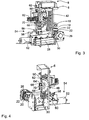
- the chassis is equipped at the bottom with a friction wheel 20 and a gear 22, in particular from the FIGS. 3 and 4 emerges, which are arranged on the same drive shaft 24 of a transmission 26 which is connected to a drive motor 28.
- the drive unit is pivotally mounted about an axis 30 on the chassis 6, so that the friction wheel 20 and the gear 22 can be alternately engaged with a friction track 32 and a rack 34 on the underside of the rail 2 in engagement.
- the rack 34 is removably mounted on a mounting rail 36 of the rail 2 and is used where the driving force of the friction wheel 20 on the friction belt 32 is no longer sufficient, ie usually on steep gradients or vertical routes.
- the chassis 6 also includes a load carrier 40, which is arranged on the side facing away from the rail 2 of the chassis 6 and about a perpendicular to the plane of the rail 2 aligned pivot axis 42 is pivotally mounted on the chassis 6.
- the load carrier 40 includes a platform 44 which is attached via a support arm 46 to a rotor block 48 which is pivotally mounted on a bearing ring 50 of the chassis 6 in this.
- the rotor block 48 cooperates with a driven by a motor 52 adjusting device 54 which is fixed to the chassis 6.
- the adjusting device 54 comprises a gear 52 connected to a motor 52, which via a belt drive 58, the toothed belt 60 drives a gear 62 which is connected to the rotor block 48.
- the assembly includes in the center a slip ring device 64 which includes a stator 66 in which leads 68 terminate which are coupled to leads 70 leading to the load carrier 40.
- the adjusting device 54 further includes a sensor 72 arranged on the load carrier 40, which responds to deviations of the load carrier from the horizontal and transmits the signals to a control device 74, which is connected to the motor 52 of the adjusting device 54 and causes it, the load carrier 40th due to the position deviating from the horizontal in the latter.
- the control device 74 as well as the adjusting device 54 may be arranged on the load carrier 40 or on the chassis 6.
- the platform 44 of the load carrier 40 is equipped with various additional devices that allow automatic loading and unloading of the load carrier at stations. These include, for example, a drivable conveyor belt 76 and guide rails 78 and limit switch 80. The arrangement of robot arms for manipulating goods is also possible.
- the chassis also includes conventional sliding contacts 82 which communicate with power or control rails 84 which are disposed on the rail 2.
- the power or control rails 84 are arranged laterally on the central web 17. This reduces maintenance because the abrasion of the power or control rails falls down and yet can not get into the lower U-profile 14. Also, the lateral U-profile 18 is protected by its upper leg from flying dust from above.
- FIGS. 6 and 7 show arcuate track sections 86 and curved track sections 88, on each of which bogies 6a circulate with load carriers 40a.
- the chassis 6a are articulated, for example via a connection support 90 with a running gear 92, wherein the load carrier 40a is pivotally mounted on the connection carrier 90.
- the load carrier 40a can either keep free oscillating due to gravity always in a horizontal position or be equipped by means of an adjusting device 54a analogous to the type described above.
Landscapes
- Engineering & Computer Science (AREA)
- Transportation (AREA)
- Mechanical Engineering (AREA)
- Chain Conveyers (AREA)
- Warehouses Or Storage Devices (AREA)
- Intermediate Stations On Conveyors (AREA)
- Platform Screen Doors And Railroad Systems (AREA)
- Handcart (AREA)
Claims (10)
- Installation de convoyage sur rail comportant au moins un châssis de roulement (6, 6a) automoteur, roulant le long de rail (2) installé dans une position quelconque, ce châssis ayant au moins une roue à friction (20) et/ou une roue dentée (22) entraînée par un moteur (28) et coopérant avec le rail (2) ainsi qu'un support de charge (40, 40a),- le rail étant réalisé et installé avec une section debout en position horizontale,
le châssis (6, 6a) étant installé pratiquement sur le côté du rail (2) et s'appuyant sur le rail (2) par des roues supérieures et inférieures (8, 10) transmettant des efforts transversaux et d'autres roues (16) transmettant des efforts verticaux, et
le support de charge (40, 40a) étant monté de façon pivotante sur le châssis (6, 6a), sur le côté opposé à celui du rail (2) et sur un axe (42) perpendiculaire au plan du rail (2),
installation caractérisée en ce que
le rail (2) comporte sur son côté supérieur un profil en U (12) ouvert vers le haut pour les roues supérieures (8) et sur son côté inférieur, un profil en U (14) ouvert vers le bas pour les roues inférieures (10), pour recevoir les efforts transversaux ainsi qu'un profil en U (18), ouvert sur le côté en direction du châssis (6, 6a) pour d'autres roues (16) pour recevoir les efforts verticaux,
les roues étant des roues de roulement. - Installation de convoyage selon la revendication 1,
caractérisée en ce que
le rail (2) a une âme centrale (17) verticale portant le profil en U supérieur (12) et le profil en U inférieur (14). - Installation de convoyage selon la revendication 2,
caractérisée en ce que
le point de raccordement d'au moins l'un des profils en U (12, 14) à l'âme centrale (17) comporte un profil creux (19). - Installation de convoyage selon l'une des revendications 1 à 3,
caractérisée en ce que
la roue de friction (20) et/ou la roue dentée (22) coopèrent avec un chemin de friction (32) ou une crémaillère (34) sur la côté inférieur du rail (2). - Installation de convoyage selon la revendication 4,
caractérisée en ce que
la crémaillère (34) est fixée de manière amovible à un profil de montage (36) du rail (2). - Installation de convoyage selon l'une des revendications 1 à 5,
caractérisée en ce que
le support de charge (40, 40a) est relié à un dispositif de positionnement (54) entraîné par un moteur (52), et comportant un capteur (72) qui détecte la position du support de charge (40, 40a) de façon que le dispositif de positionnement (54) ramène ou maintienne en position horizontale le support de charge lors du passage sur des segments de trajet orientés différemment de la direction horizontale. - Installation de convoyage selon la revendication 6,
caractérisée en ce que
le support de charge (40, 40a) est relié à un bloc de rotor (48) monté en rotation dans un palier (50) du châssis (6, 6a) et relié au dispositif de positionnement (54). - Installation de convoyage selon la revendication 7,
caractérisée en ce que
le bloc de rotor (48) et le dispositif de positionnement (54) sont montés directement sur le châssis (6). - Installation de convoyage selon la revendication 7,
caractérisée en ce que
le bloc de rotor (48) et le dispositif de positionnement (54) sont installés sur un support de liaison (09) et ce dernier relie de manière articulée le châssis (6a) à un autre châssis de circulation (92) circulant sur le rail (2). - Installation de convoyage selon la revendication 7,
caractérisée en ce que
le support de charge (40) est relié à une plateforme (44) recevant la charge à transporteur, cette plateforme étant reliée au bloc de rotor (48) par un bras (46).
Priority Applications (2)
| Application Number | Priority Date | Filing Date | Title |
|---|---|---|---|
| PL08707411T PL2117902T3 (pl) | 2007-02-05 | 2008-01-30 | Przenośnik łączony szynami |
| EP08707411A EP2117902B1 (fr) | 2007-02-05 | 2008-01-30 | Installation de convoyage sur rail |
Applications Claiming Priority (3)
| Application Number | Priority Date | Filing Date | Title |
|---|---|---|---|
| EP07002442 | 2007-02-05 | ||
| PCT/EP2008/000716 WO2008095634A1 (fr) | 2007-02-05 | 2008-01-30 | Installation de convoyage sur rail |
| EP08707411A EP2117902B1 (fr) | 2007-02-05 | 2008-01-30 | Installation de convoyage sur rail |
Publications (2)
| Publication Number | Publication Date |
|---|---|
| EP2117902A1 EP2117902A1 (fr) | 2009-11-18 |
| EP2117902B1 true EP2117902B1 (fr) | 2010-09-29 |
Family
ID=38255434
Family Applications (1)
| Application Number | Title | Priority Date | Filing Date |
|---|---|---|---|
| EP08707411A Active EP2117902B1 (fr) | 2007-02-05 | 2008-01-30 | Installation de convoyage sur rail |
Country Status (7)
| Country | Link |
|---|---|
| EP (1) | EP2117902B1 (fr) |
| CN (1) | CN101646589B (fr) |
| AT (1) | ATE482862T1 (fr) |
| DE (1) | DE502008001445D1 (fr) |
| ES (1) | ES2353244T3 (fr) |
| PL (1) | PL2117902T3 (fr) |
| WO (1) | WO2008095634A1 (fr) |
Families Citing this family (6)
| Publication number | Priority date | Publication date | Assignee | Title |
|---|---|---|---|---|
| US4829455A (en) * | 1986-04-11 | 1989-05-09 | Quantel Limited | Graphics system for video and printed images |
| ES2667855T3 (es) | 2011-12-30 | 2018-05-14 | Siemens Aktiengesellschaft | Dispositivo de transporte para materiales a transportar ligeros, particularmente piezas de vehículos |
| EP2679475A1 (fr) | 2012-06-29 | 2014-01-01 | Siemens Aktiengesellschaft | Dispositif d'appui pour carrosseries de véhicules présentant des longueurs différentes |
| CN103770790B (zh) * | 2014-02-20 | 2016-10-05 | 四川大学 | 高架式轨道运输平台系统 |
| DE102016117543B4 (de) * | 2016-09-16 | 2018-09-27 | Dieffenbacher GmbH Maschinen- und Anlagenbau | Überführungseinrichtung einer oder für eine Fördervorrichtung, Fördervorrichtung, Produktionsanlage und Verfahren zum Betreiben einer Produktionsanlage |
| CN107640161B (zh) * | 2017-10-31 | 2023-04-11 | 中唐空铁集团有限公司 | 一种悬挂空铁平稳升降运行系统 |
Family Cites Families (7)
| Publication number | Priority date | Publication date | Assignee | Title |
|---|---|---|---|---|
| CH515819A (de) * | 1969-09-24 | 1971-11-30 | Buero Patent Ag | Geleisegebundene Förderanlage |
| US4531460A (en) * | 1982-03-10 | 1985-07-30 | Litton Systems, Inc. | Material handling system |
| IT1241172B (it) * | 1990-02-13 | 1993-12-29 | F Sistemi Automazioni Flessibi | Impianto di trasporto monorotaia e carrello motorizzato per tale impianto. |
| US5419260A (en) * | 1993-12-15 | 1995-05-30 | Hamilton; James | Self-propelled overhead track-mounted moving system |
| ES2135933T3 (es) * | 1995-11-09 | 1999-11-01 | Telelift Gmbh | Instalacion de transporte sobre carriles y procedimiento para su operacion. |
| CN1294043C (zh) * | 2002-03-18 | 2007-01-10 | 吴文湛 | 侧挂式运输设备 |
| JP3782798B2 (ja) * | 2003-07-07 | 2006-06-07 | 泉陽機工株式会社 | モノレール装置 |
-
2008
- 2008-01-30 AT AT08707411T patent/ATE482862T1/de active
- 2008-01-30 DE DE502008001445T patent/DE502008001445D1/de active Active
- 2008-01-30 PL PL08707411T patent/PL2117902T3/pl unknown
- 2008-01-30 CN CN2008800105167A patent/CN101646589B/zh active Active
- 2008-01-30 EP EP08707411A patent/EP2117902B1/fr active Active
- 2008-01-30 ES ES08707411T patent/ES2353244T3/es active Active
- 2008-01-30 WO PCT/EP2008/000716 patent/WO2008095634A1/fr not_active Ceased
Also Published As
| Publication number | Publication date |
|---|---|
| DE502008001445D1 (de) | 2010-11-11 |
| CN101646589B (zh) | 2012-05-16 |
| ATE482862T1 (de) | 2010-10-15 |
| EP2117902A1 (fr) | 2009-11-18 |
| WO2008095634A1 (fr) | 2008-08-14 |
| PL2117902T3 (pl) | 2011-05-31 |
| ES2353244T3 (es) | 2011-02-28 |
| CN101646589A (zh) | 2010-02-10 |
Similar Documents
| Publication | Publication Date | Title |
|---|---|---|
| DE3109944C2 (de) | Kuppelbare Umlauf-Drahtseilbahn zur Beförderung von Material, wie Schüttgut | |
| EP0156304B1 (fr) | Dispositif pour l'inspection des parties inférieures des ponts | |
| EP1761445B1 (fr) | Dispositif convoyeur pour le transport de marchandises sur des palettes le long d'une voie de transport horizontale | |
| EP2117902B1 (fr) | Installation de convoyage sur rail | |
| EP1930225B1 (fr) | Dispositif pour le stockage de télésièges ou télécabines d'un téléphérique dans une zone de stockage | |
| EP2677095A2 (fr) | Monte-personnes pour parois en surplomb ou à courbure convexe | |
| EP3212560B1 (fr) | Appareil élévateur à portique pour conteneurs iso | |
| EP1840072B1 (fr) | Grue dotée d'un bras et d'une bande de déroulement pour les chariots porte câbles | |
| EP2365931A1 (fr) | Procédé et installation permettant de transborder des supports de chargement standardisés, en particulier des conteneurs iso et des caisses mobiles, entre le rail et la route | |
| DE102010014596B4 (de) | Fahrzeug zur Durchführung von Baumaßnahmen im Gleisbereich des Eisenbahnverkehrs | |
| DE2504966A1 (de) | Hochbahn-transportsystem | |
| EP1426309A1 (fr) | Transstockeur | |
| EP2484607B1 (fr) | Dispositif de transport et installation de transport équipée de ce dispositif | |
| DE19955801A1 (de) | Transportvorrichtung zum Befördern von Lasten in vertikaler Richtung zwischen horizontalen Ebenen | |
| DE102006047864A1 (de) | Fördereinrichtung zum Quertransport langgestreckter Werkstücke | |
| EP2350389A2 (fr) | Dispositif pour transférer des articles et système de transport le comprenant | |
| DE3545298C2 (fr) | ||
| DE4427468A1 (de) | Eine aus zwei Kränen bestehende Krananlage, die auf ein Straßen-, Schienen- oder Binnenwasserfahrzeug aufgebaut ist und die für das Fördern von Containern und Wechselbehältern geeignet ist | |
| EP0073848B1 (fr) | Disposition de poulies pour un chemin de fer monorail suspendu entraîné par câble | |
| DE102010055348B4 (de) | Überführungsvorrichtung für Transportwagen und Förderanlage mit einer solchen | |
| DE19723768A1 (de) | Transportmittel für Personen und Material im untertägigen Berg- und Tunnelbau | |
| DE3425999C2 (fr) | ||
| WO2010100532A1 (fr) | Chariot de téléphérique avec câbles de traction, cabine de téléphérique et installation de téléphérique | |
| DE102005018424B4 (de) | Fördersystem zum gleichzeitigen Transport von Werkstücken und Monteuren in einer Fertigungslinie | |
| DE1963043A1 (de) | Foerderzeug fuer Hochregale mit an Gaengen angeordneten Abstellplaetzen zur Aufnahme von Platten,Containern,Kraftfahrzeugen u.dgl. |
Legal Events
| Date | Code | Title | Description |
|---|---|---|---|
| PUAI | Public reference made under article 153(3) epc to a published international application that has entered the european phase |
Free format text: ORIGINAL CODE: 0009012 |
|
| 17P | Request for examination filed |
Effective date: 20090724 |
|
| AK | Designated contracting states |
Kind code of ref document: A1 Designated state(s): AT BE BG CH CY CZ DE DK EE ES FI FR GB GR HR HU IE IS IT LI LT LU LV MC MT NL NO PL PT RO SE SI SK TR |
|
| GRAP | Despatch of communication of intention to grant a patent |
Free format text: ORIGINAL CODE: EPIDOSNIGR1 |
|
| DAX | Request for extension of the european patent (deleted) | ||
| GRAS | Grant fee paid |
Free format text: ORIGINAL CODE: EPIDOSNIGR3 |
|
| GRAA | (expected) grant |
Free format text: ORIGINAL CODE: 0009210 |
|
| AK | Designated contracting states |
Kind code of ref document: B1 Designated state(s): AT BE BG CH CY CZ DE DK EE ES FI FR GB GR HR HU IE IS IT LI LT LU LV MC MT NL NO PL PT RO SE SI SK TR |
|
| REG | Reference to a national code |
Ref country code: GB Ref legal event code: FG4D Free format text: NOT ENGLISH |
|
| REG | Reference to a national code |
Ref country code: CH Ref legal event code: EP |
|
| REG | Reference to a national code |
Ref country code: IE Ref legal event code: FG4D Free format text: LANGUAGE OF EP DOCUMENT: GERMAN |
|
| REF | Corresponds to: |
Ref document number: 502008001445 Country of ref document: DE Date of ref document: 20101111 Kind code of ref document: P |
|
| REG | Reference to a national code |
Ref country code: SE Ref legal event code: TRGR |
|
| PG25 | Lapsed in a contracting state [announced via postgrant information from national office to epo] |
Ref country code: LT Free format text: LAPSE BECAUSE OF FAILURE TO SUBMIT A TRANSLATION OF THE DESCRIPTION OR TO PAY THE FEE WITHIN THE PRESCRIBED TIME-LIMIT Effective date: 20100929 Ref country code: FI Free format text: LAPSE BECAUSE OF FAILURE TO SUBMIT A TRANSLATION OF THE DESCRIPTION OR TO PAY THE FEE WITHIN THE PRESCRIBED TIME-LIMIT Effective date: 20100929 Ref country code: NO Free format text: LAPSE BECAUSE OF FAILURE TO SUBMIT A TRANSLATION OF THE DESCRIPTION OR TO PAY THE FEE WITHIN THE PRESCRIBED TIME-LIMIT Effective date: 20101229 |
|
| REG | Reference to a national code |
Ref country code: NL Ref legal event code: VDEP Effective date: 20100929 |
|
| LTIE | Lt: invalidation of european patent or patent extension |
Effective date: 20100929 |
|
| PG25 | Lapsed in a contracting state [announced via postgrant information from national office to epo] |
Ref country code: HR Free format text: LAPSE BECAUSE OF FAILURE TO SUBMIT A TRANSLATION OF THE DESCRIPTION OR TO PAY THE FEE WITHIN THE PRESCRIBED TIME-LIMIT Effective date: 20100929 Ref country code: SI Free format text: LAPSE BECAUSE OF FAILURE TO SUBMIT A TRANSLATION OF THE DESCRIPTION OR TO PAY THE FEE WITHIN THE PRESCRIBED TIME-LIMIT Effective date: 20100929 |
|
| REG | Reference to a national code |
Ref country code: ES Ref legal event code: FG2A Effective date: 20110216 |
|
| PG25 | Lapsed in a contracting state [announced via postgrant information from national office to epo] |
Ref country code: GR Free format text: LAPSE BECAUSE OF FAILURE TO SUBMIT A TRANSLATION OF THE DESCRIPTION OR TO PAY THE FEE WITHIN THE PRESCRIBED TIME-LIMIT Effective date: 20101230 Ref country code: LV Free format text: LAPSE BECAUSE OF FAILURE TO SUBMIT A TRANSLATION OF THE DESCRIPTION OR TO PAY THE FEE WITHIN THE PRESCRIBED TIME-LIMIT Effective date: 20100929 |
|
| REG | Reference to a national code |
Ref country code: IE Ref legal event code: FD4D |
|
| PG25 | Lapsed in a contracting state [announced via postgrant information from national office to epo] |
Ref country code: CZ Free format text: LAPSE BECAUSE OF FAILURE TO SUBMIT A TRANSLATION OF THE DESCRIPTION OR TO PAY THE FEE WITHIN THE PRESCRIBED TIME-LIMIT Effective date: 20100929 Ref country code: NL Free format text: LAPSE BECAUSE OF FAILURE TO SUBMIT A TRANSLATION OF THE DESCRIPTION OR TO PAY THE FEE WITHIN THE PRESCRIBED TIME-LIMIT Effective date: 20100929 Ref country code: SK Free format text: LAPSE BECAUSE OF FAILURE TO SUBMIT A TRANSLATION OF THE DESCRIPTION OR TO PAY THE FEE WITHIN THE PRESCRIBED TIME-LIMIT Effective date: 20100929 Ref country code: RO Free format text: LAPSE BECAUSE OF FAILURE TO SUBMIT A TRANSLATION OF THE DESCRIPTION OR TO PAY THE FEE WITHIN THE PRESCRIBED TIME-LIMIT Effective date: 20100929 Ref country code: IS Free format text: LAPSE BECAUSE OF FAILURE TO SUBMIT A TRANSLATION OF THE DESCRIPTION OR TO PAY THE FEE WITHIN THE PRESCRIBED TIME-LIMIT Effective date: 20110129 Ref country code: EE Free format text: LAPSE BECAUSE OF FAILURE TO SUBMIT A TRANSLATION OF THE DESCRIPTION OR TO PAY THE FEE WITHIN THE PRESCRIBED TIME-LIMIT Effective date: 20100929 Ref country code: PT Free format text: LAPSE BECAUSE OF FAILURE TO SUBMIT A TRANSLATION OF THE DESCRIPTION OR TO PAY THE FEE WITHIN THE PRESCRIBED TIME-LIMIT Effective date: 20110131 |
|
| REG | Reference to a national code |
Ref country code: PL Ref legal event code: T3 |
|
| PG25 | Lapsed in a contracting state [announced via postgrant information from national office to epo] |
Ref country code: IE Free format text: LAPSE BECAUSE OF FAILURE TO SUBMIT A TRANSLATION OF THE DESCRIPTION OR TO PAY THE FEE WITHIN THE PRESCRIBED TIME-LIMIT Effective date: 20100929 |
|
| BERE | Be: lapsed |
Owner name: SWISSLOG TELELIFT G.M.B.H. Effective date: 20110131 |
|
| PLBE | No opposition filed within time limit |
Free format text: ORIGINAL CODE: 0009261 |
|
| STAA | Information on the status of an ep patent application or granted ep patent |
Free format text: STATUS: NO OPPOSITION FILED WITHIN TIME LIMIT |
|
| PG25 | Lapsed in a contracting state [announced via postgrant information from national office to epo] |
Ref country code: MC Free format text: LAPSE BECAUSE OF NON-PAYMENT OF DUE FEES Effective date: 20110131 Ref country code: DK Free format text: LAPSE BECAUSE OF FAILURE TO SUBMIT A TRANSLATION OF THE DESCRIPTION OR TO PAY THE FEE WITHIN THE PRESCRIBED TIME-LIMIT Effective date: 20100929 |
|
| REG | Reference to a national code |
Ref country code: DE Ref legal event code: R097 Ref document number: 502008001445 Country of ref document: DE Effective date: 20110630 |
|
| PG25 | Lapsed in a contracting state [announced via postgrant information from national office to epo] |
Ref country code: BE Free format text: LAPSE BECAUSE OF NON-PAYMENT OF DUE FEES Effective date: 20110131 |
|
| PG25 | Lapsed in a contracting state [announced via postgrant information from national office to epo] |
Ref country code: MT Free format text: LAPSE BECAUSE OF FAILURE TO SUBMIT A TRANSLATION OF THE DESCRIPTION OR TO PAY THE FEE WITHIN THE PRESCRIBED TIME-LIMIT Effective date: 20100929 |
|
| REG | Reference to a national code |
Ref country code: CH Ref legal event code: PL |
|
| PG25 | Lapsed in a contracting state [announced via postgrant information from national office to epo] |
Ref country code: CH Free format text: LAPSE BECAUSE OF NON-PAYMENT OF DUE FEES Effective date: 20120131 Ref country code: LI Free format text: LAPSE BECAUSE OF NON-PAYMENT OF DUE FEES Effective date: 20120131 |
|
| PG25 | Lapsed in a contracting state [announced via postgrant information from national office to epo] |
Ref country code: LU Free format text: LAPSE BECAUSE OF NON-PAYMENT OF DUE FEES Effective date: 20110130 Ref country code: CY Free format text: LAPSE BECAUSE OF FAILURE TO SUBMIT A TRANSLATION OF THE DESCRIPTION OR TO PAY THE FEE WITHIN THE PRESCRIBED TIME-LIMIT Effective date: 20100929 |
|
| PG25 | Lapsed in a contracting state [announced via postgrant information from national office to epo] |
Ref country code: BG Free format text: LAPSE BECAUSE OF FAILURE TO SUBMIT A TRANSLATION OF THE DESCRIPTION OR TO PAY THE FEE WITHIN THE PRESCRIBED TIME-LIMIT Effective date: 20101229 Ref country code: TR Free format text: LAPSE BECAUSE OF FAILURE TO SUBMIT A TRANSLATION OF THE DESCRIPTION OR TO PAY THE FEE WITHIN THE PRESCRIBED TIME-LIMIT Effective date: 20100929 |
|
| PG25 | Lapsed in a contracting state [announced via postgrant information from national office to epo] |
Ref country code: HU Free format text: LAPSE BECAUSE OF FAILURE TO SUBMIT A TRANSLATION OF THE DESCRIPTION OR TO PAY THE FEE WITHIN THE PRESCRIBED TIME-LIMIT Effective date: 20100929 |
|
| REG | Reference to a national code |
Ref country code: AT Ref legal event code: MM01 Ref document number: 482862 Country of ref document: AT Kind code of ref document: T Effective date: 20130130 |
|
| PG25 | Lapsed in a contracting state [announced via postgrant information from national office to epo] |
Ref country code: AT Free format text: LAPSE BECAUSE OF NON-PAYMENT OF DUE FEES Effective date: 20130130 |
|
| REG | Reference to a national code |
Ref country code: DE Ref legal event code: R082 Ref document number: 502008001445 Country of ref document: DE Representative=s name: MAIKOWSKI & NINNEMANN PATENTANWAELTE, DE |
|
| REG | Reference to a national code |
Ref country code: FR Ref legal event code: TP Owner name: TELELIFT GMBH, DE Effective date: 20150112 |
|
| REG | Reference to a national code |
Ref country code: GB Ref legal event code: 732E Free format text: REGISTERED BETWEEN 20150122 AND 20150128 |
|
| REG | Reference to a national code |
Ref country code: DE Ref legal event code: R082 Ref document number: 502008001445 Country of ref document: DE Representative=s name: MAIKOWSKI & NINNEMANN PATENTANWAELTE, DE Effective date: 20150115 Ref country code: DE Ref legal event code: R081 Ref document number: 502008001445 Country of ref document: DE Owner name: TELELIFT GMBH, DE Free format text: FORMER OWNER: SWISSLOG TELELIFT GMBH, 82178 PUCHHEIM, DE Effective date: 20150115 Ref country code: DE Ref legal event code: R082 Ref document number: 502008001445 Country of ref document: DE Representative=s name: MAIKOWSKI & NINNEMANN PATENTANWAELTE PARTNERSC, DE Effective date: 20150115 |
|
| REG | Reference to a national code |
Ref country code: ES Ref legal event code: PC2A Owner name: TELELIFT GMBH Effective date: 20150810 |
|
| REG | Reference to a national code |
Ref country code: FR Ref legal event code: PLFP Year of fee payment: 9 |
|
| REG | Reference to a national code |
Ref country code: FR Ref legal event code: PLFP Year of fee payment: 10 |
|
| REG | Reference to a national code |
Ref country code: FR Ref legal event code: PLFP Year of fee payment: 11 |
|
| PGFP | Annual fee paid to national office [announced via postgrant information from national office to epo] |
Ref country code: PL Payment date: 20171218 Year of fee payment: 11 |
|
| PGFP | Annual fee paid to national office [announced via postgrant information from national office to epo] |
Ref country code: ES Payment date: 20180227 Year of fee payment: 11 |
|
| PGFP | Annual fee paid to national office [announced via postgrant information from national office to epo] |
Ref country code: IT Payment date: 20180129 Year of fee payment: 11 Ref country code: SE Payment date: 20180119 Year of fee payment: 11 Ref country code: FR Payment date: 20180119 Year of fee payment: 11 |
|
| PG25 | Lapsed in a contracting state [announced via postgrant information from national office to epo] |
Ref country code: SE Free format text: LAPSE BECAUSE OF NON-PAYMENT OF DUE FEES Effective date: 20190131 Ref country code: FR Free format text: LAPSE BECAUSE OF NON-PAYMENT OF DUE FEES Effective date: 20190131 |
|
| PG25 | Lapsed in a contracting state [announced via postgrant information from national office to epo] |
Ref country code: IT Free format text: LAPSE BECAUSE OF NON-PAYMENT OF DUE FEES Effective date: 20190130 |
|
| REG | Reference to a national code |
Ref country code: ES Ref legal event code: FD2A Effective date: 20200310 |
|
| PG25 | Lapsed in a contracting state [announced via postgrant information from national office to epo] |
Ref country code: ES Free format text: LAPSE BECAUSE OF NON-PAYMENT OF DUE FEES Effective date: 20190131 |
|
| PG25 | Lapsed in a contracting state [announced via postgrant information from national office to epo] |
Ref country code: PL Free format text: LAPSE BECAUSE OF NON-PAYMENT OF DUE FEES Effective date: 20190130 |
|
| PGFP | Annual fee paid to national office [announced via postgrant information from national office to epo] |
Ref country code: GB Payment date: 20260123 Year of fee payment: 19 |
|
| PGFP | Annual fee paid to national office [announced via postgrant information from national office to epo] |
Ref country code: DE Payment date: 20260121 Year of fee payment: 19 |