EP2118429B1 - Lenksystem und -verfahren für einen drehbohrer - Google Patents
Lenksystem und -verfahren für einen drehbohrer Download PDFInfo
- Publication number
- EP2118429B1 EP2118429B1 EP08728825.4A EP08728825A EP2118429B1 EP 2118429 B1 EP2118429 B1 EP 2118429B1 EP 08728825 A EP08728825 A EP 08728825A EP 2118429 B1 EP2118429 B1 EP 2118429B1
- Authority
- EP
- European Patent Office
- Prior art keywords
- section
- drill bit
- bit
- gage
- heel
- Prior art date
- Legal status (The legal status is an assumption and is not a legal conclusion. Google has not performed a legal analysis and makes no representation as to the accuracy of the status listed.)
- Not-in-force
Links
- 238000000034 method Methods 0.000 title claims description 10
- 238000005553 drilling Methods 0.000 description 46
- 230000008859 change Effects 0.000 description 12
- 230000015572 biosynthetic process Effects 0.000 description 11
- 238000005755 formation reaction Methods 0.000 description 11
- 230000035515 penetration Effects 0.000 description 10
- 230000007704 transition Effects 0.000 description 9
- 239000012530 fluid Substances 0.000 description 5
- 239000000463 material Substances 0.000 description 5
- 239000011159 matrix material Substances 0.000 description 5
- 230000000712 assembly Effects 0.000 description 4
- 238000000429 assembly Methods 0.000 description 4
- 210000001331 nose Anatomy 0.000 description 4
- 230000008901 benefit Effects 0.000 description 3
- 239000003381 stabilizer Substances 0.000 description 3
- 229910000831 Steel Inorganic materials 0.000 description 2
- 229910003460 diamond Inorganic materials 0.000 description 2
- 239000010432 diamond Substances 0.000 description 2
- 230000003993 interaction Effects 0.000 description 2
- 239000010959 steel Substances 0.000 description 2
- 238000005481 NMR spectroscopy Methods 0.000 description 1
- 239000003082 abrasive agent Substances 0.000 description 1
- 230000009471 action Effects 0.000 description 1
- 230000003466 anti-cipated effect Effects 0.000 description 1
- 238000006073 displacement reaction Methods 0.000 description 1
- 230000003628 erosive effect Effects 0.000 description 1
- 230000005251 gamma ray Effects 0.000 description 1
- 238000005552 hardfacing Methods 0.000 description 1
- 238000005259 measurement Methods 0.000 description 1
- 230000007246 mechanism Effects 0.000 description 1
- 229910001092 metal group alloy Inorganic materials 0.000 description 1
- 239000011435 rock Substances 0.000 description 1
- 238000004088 simulation Methods 0.000 description 1
- 230000000087 stabilizing effect Effects 0.000 description 1
- 238000006467 substitution reaction Methods 0.000 description 1
- UONOETXJSWQNOL-UHFFFAOYSA-N tungsten carbide Chemical compound [W+]#[C-] UONOETXJSWQNOL-UHFFFAOYSA-N 0.000 description 1
Images




Classifications
-
- E—FIXED CONSTRUCTIONS
- E21—EARTH OR ROCK DRILLING; MINING
- E21B—EARTH OR ROCK DRILLING; OBTAINING OIL, GAS, WATER, SOLUBLE OR MELTABLE MATERIALS OR A SLURRY OF MINERALS FROM WELLS
- E21B7/00—Special methods or apparatus for drilling
- E21B7/04—Directional drilling
- E21B7/06—Deflecting the direction of boreholes
- E21B7/064—Deflecting the direction of boreholes specially adapted drill bits therefor
-
- E—FIXED CONSTRUCTIONS
- E21—EARTH OR ROCK DRILLING; MINING
- E21B—EARTH OR ROCK DRILLING; OBTAINING OIL, GAS, WATER, SOLUBLE OR MELTABLE MATERIALS OR A SLURRY OF MINERALS FROM WELLS
- E21B10/00—Drill bits
- E21B10/42—Rotary drag type drill bits with teeth, blades or like cutting elements, e.g. fork-type bits, fish tail bits
- E21B10/43—Rotary drag type drill bits with teeth, blades or like cutting elements, e.g. fork-type bits, fish tail bits characterised by the arrangement of teeth or other cutting elements
Definitions
- the present disclosure is related to wellbore drilling equipment and more particularly to rotary drill bits and/or bottom hole assemblies with steerability.
- Various types of rotary drill bits have been used to form wellbores or boreholes in downhole formations. Such wellbores are often formed using a rotary drill bit attached to the end of a generally hollow, tubular drill string extending from an associated well surface. Rotation of a rotary drill bit progressively cuts away adjacent portions of a downhole formation using cutting elements and cutting structures disposed on exterior portions of the rotary drill bit. Examples of rotary drill bits include fixed cutter drill bits or drag drill bits, impregnated diamond bits and matrix drill bits.
- Various types of drilling fluids are generally used with rotary drill bits to form wellbores or boreholes extending from a well surface through one or more downhole formations.
- Bottom hole assemblies have been used consisting of the drill bit, stabilizers, drill collars, heavy weight pipe, and a positive displacement motor (mud motor) having a bent housing.
- the bottom hole assembly is connected to a drill string or drill pipe extending to the surface.
- the assembly steers by sliding (not rotating) the assembly with the bend in the bent housing in a specific direction to cause a change in the borehole direction.
- the assembly and drill string are rotated to drill straight.
- EP 0 178 709 A1 relates to a device for stabilizing a drill string, consisting of a steel cylinder having helical protrusions.
- EP 2 264 275 A2 discloses methods and systems for design and/or selecting of drilling equipment based on wellbore drilling simulations and was cited under Article 54(3) EPC.
- GB 2 212 091 A relates to drilling equipment for the drilling of holes in rock by percussive techniques.
- Document US 5 004 057 A1 discloses a drill bit comprising: a cutting section comprising gage cutters, wherein the cutting section is a first end of the bit, and wherein the cutting section has a full gage diameter; a heel section comprising a blade, wherein the heel section is at an end of the drill bit opposite the cutting section, and wherein a diameter of the heel section is a full gage diameter; and a clearance section between the cutting and heel sections, wherein the clearance section has a diameter less than full gage, and wherein the clearance section extends from the gage cutters of the cutting section to the blade of the heel section.
- rotary drill bits including fixed cutter drill bits may be designed with steerability and/or controllability optimized for a desired wellbore profile and/or anticipated downhole drilling conditions.
- a drill bit comprising: a cutting section comprising gage cutters, wherein in the cutting section is a first end of the bit, and wherein the cutting section has a full gage diameter; a heel section
- the heel section is at an end of the drill bit opposite the cutting section, and wherein a diameter of the heel section is a full gage diameter; and a clearance section between the cutting and heel sections, wherein the clearance section has a diameter less than full gage and comprises a blade having an outside diameter less than full gage, and wherein the clearance section extends from the gage cutters of the cutting section to the blade of the heel section.
- a method for steering a rotary drill bit comprising: running a bottom hole assembly and a drill bit into a wellbore, wherein the drill bit comprises a cutting section, a heel section and a clearance section, wherein the cutting and heel sections comprise full gage diameters and the clearance section comprises a diameter less than full gage, and wherein the clearance section extends from gage cutters of the cutting section to a blade of the heel section; articulating the drill bit relative to the bottom hole assembly; and kicking the heel section of the drill bit off a wellbore side wall.
- FIGURES 1-7B wherein like numerals may be used for like and corresponding parts of the various drawings.
- bottom hole assembly or “BHA” may be used in this application to describe various components and assemblies disposed proximate to a rotary drill bit at the downhole end of a drill string.
- components and assemblies which may be included in a bottom hole assembly or BHA include, but are not limited to, a bent sub, a downhole drilling motor, a near bit reamer, stabilizers and down hole instruments.
- a bottom hole assembly may also include various types of well logging tools (not expressly shown) and other downhole instruments associated with directional drilling of a wellbore. Examples of such logging tools and/or directional drilling equipment may include, but are not limited to, acoustic, neutron, gamma ray, density, photoelectric, nuclear magnetic resonance and/or any other commercially available logging instruments.
- cutter may be used in this application to include various types of compacts, inserts, milled teeth, welded compacts and gage cutters satisfactory for use with a wide variety of rotary drill bits.
- Impact arrestors which may be included as part of the cutting structure on some types of rotary drill bits, may function as cutters to remove formation materials from adjacent portions of a wellbore. Impact arrestors or any other portion of the cutting structure of a rotary drill bit may be analyzed and evaluated using various techniques and procedures as discussed herein with respect to cutters.
- Polycrystalline diamond compacts (PDC) and tungsten carbide inserts may be used to form cutters for rotary drill bits.
- a wide variety of other types of hard, abrasive materials may also be satisfactorily used to form such cutters.
- cutting element and “cutlet” may be used to describe a small portion or segment of an associated cutter which interacts with adjacent portions of a wellbore and may be used to simulate interaction between the cutter and adjacent portions of a wellbore.
- cutters and other portions of a rotary drill bit may also be meshed into small segments or portions sometimes referred to as “mesh units” for purposes of analyzing interaction between each small portion or segment and adjacent portions of a wellbore.
- cutting structure may be used in this application to include various combinations and arrangements of cutters, face cutters, impact arrestors and/or gage cutters formed on exterior portions of a rotary drill bit.
- Some fixed cutter drill bits may include one or more blades extending from an associated bit body with cutters disposed on the blades.
- Various configurations of blades and cutters may be used to form cutting structures for a fixed cutter drill bit.
- rotary drill bit may be used in this application to include various types of fixed cutter drill bits, drag bits and matrix drill bits operable to form a wellbore extending through one or more downhole formations.
- Rotary drill bits and associated components formed in accordance with teachings of the present disclosure may have many different designs and configurations.
- a stabilizer located relatively close to a roller cone drill bit (not expressly shown) may function similar to a passive gage portion of a fixed cutter drill bit.
- a near bit reamer located relatively close to a roller cone drill bit may function similar to an active gage portion of a fixed cutter drill bit.
- straight hole may be used in this application to describe a wellbore or portions of a wellbore that extends at generally a constant angle relative to vertical.
- Vertical wellbores and horizontal wellbores are examples of straight holes.
- slant hole and “slant hole segment” may be used in this application to describe a straight hole formed at a substantially constant angle relative to vertical.
- the constant angle of a slant hole is typically less than ninety (90) degrees and greater than zero (0) degrees.
- a slant hole may have similar variations depending upon the length and associated drilling equipment used to form the slant hole.
- directional wellbore may be used in this application to describe a wellbore or portions of a wellbore that extend at a desired angle or angles relative to vertical. Such angles are greater than normal variations associated with straight holes.
- a directional wellbore sometimes may be described as a wellbore deviated from vertical.
- Sections, segments and/or portions of a directional wellbore may include, but are not limited to, a vertical section, a kick off section, a building section, a holding section and/or a dropping section.
- a vertical section may have substantially no change in degrees from vertical.
- Holding sections such as slant hole segments and horizontal segments may extend at respective fixed angles relative to vertical and may have substantially zero rate of change in degrees from vertical.
- Transition sections formed between straight hole portions of a wellbore may include, but are not limited to, kick off segments, building segments and dropping segments. Such transition sections generally have a rate of change in degrees greater than zero. Building segments generally have a positive rate of change in degrees. Dropping segments generally have a negative rate of change in degrees. The rate of change in degrees may vary along the length of all or portions of a transition section or may be substantially constant along the length of all or portions of the transition section.
- kick off segment may be used to describe a portion or section of a wellbore forming a transition between the end point of a straight hole segment and the first point where a desired DLS or tilt rate is achieved.
- a kick off segment may be formed as a transition from a vertical wellbore to an equilibrium wellbore with a constant curvature or tilt rate.
- a kick off segment of a wellbore may have a variable curvature and a variable rate of change in degrees from vertical (variable tilt rate).
- a building segment having a relatively constant radius and a relatively constant change in degrees from vertical may be used to form a transition from vertical segments to a slant hole segment or horizontal segment of a wellbore.
- a dropping segment may have a relatively constant radius and a relatively constant change in degrees from vertical (constant tilt rate) may be used to form a transition from a slant hole segment or a horizontal segment to a vertical segment of a wellbore. See FIGURE 1A .
- a transition between a vertical segment and a horizontal segment may only be a building segment having a relatively constant radius and a relatively constant change in degrees from vertical. See FIGURE 1B .
- Building segments and dropping segments may also be described as "equilibrium" segments.
- DLS dogleg severity
- a straight hole, vertical hole, slant hole or horizontal hole will generally have a value of DLS of approximately zero. DLS may be positive, negative or zero.
- FIGURE 1 a cross-sectional side view of a wellbore and directional drilling equipment is shown.
- Directional drilling system 20 and wellbore 60 as shown in FIGURE 1 may be used to describe various features of the present disclosure, including drill rig 22, drilling string 32, bottom hole assembly 90 and associated rotary drill bit 100.
- Bottom hole assembly 90 may include various components associated with a measurement while drilling (MWD) system that provides logging data and other information from the bottom of wellbore 60 to directional drilling equipment 50.
- Logging data and other information may be communicated from end 62 of wellbore 60 through drill string 32 using MWD techniques and converted to electrical signals at well surface 24.
- Electrical conduit or wires 52 may communicate the electrical signals to directional drilling equipment 50.
- Bottom hole assembly 90 may have a flexible shaft in the middle of the tool with an internal cam to bias the tool to point-the-bit. An outer housing of the tool does not rotate with the drill string, but rather it may engage the sidewall of the wellbore to point-the-bit.
- Rotary drill bit 100 extends from bottom hole assembly 90 to the end 62 of wellbore 60.
- Bottom hole assembly 90 is aligned with vertical axis 74 while rotary drill bit 100 is aligned with rate of penetration axis 76.
- Kick-off load 78 is applied by the side wall of wellbore 60 on a heel portion of rotary drill bit 100 to point-the-bit in the direction of rate of penetration axis 76.
- FIGURE 2B illustrates a side view of the rotary drill bit shown in FIGURE 2A .
- Rotary drill bit 100 has cutting section 101, heel section 102 and clearance section 103.
- Cutting section 101 has a full gage diameter at its widest portions.
- heel section 102 also has a full gage diameter.
- Clearance section 102 has a diameter less than full gage, so that its diameter is less than cutting section 101 and heel section 102.
- the point load of the blades on the formation may be reduced, whereby the propensity of the blades to sidecut the side wall may also be reduced.
- the blades in heel section 102 may be wider than the spaces between the blades and the spiral of the blades may be sufficiently high so that a larger blade surface area is in contact with the side wall of the wellbore at the fulcrum point.
- a larger area of surface contact by the blades on the side wall of the wellbore may distribute kick-off load 78 over a larger portion of the side wall of the wellbore so that the point loads across the contact area is reduced.
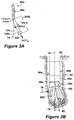
- FIGURE 3A shows portions of bottom hole assembly 90 disposed in a generally vertical section of wellbore 60a as rotary drill bit 100c begins to form kick off segment 60b.
- Bottom hole assembly 90b includes rotary drill bit steering unit 92b which may provide one portion of a point-the-bit directional drilling system.
- Point-the-bit directional drilling systems typically form a directional wellbore using a combination of axial bit penetration, bit rotation and bit tilting. Point-the-bit directional drilling systems may not produce side penetration such as described with respect to steering unit 92b in FIGURE 3A . Therefore, bit side penetration is generally not created by point-the-bit directional drilling systems to form a directional wellbore.
- One example of a point-the-bit directional drilling system is the Geo-Pilot® Rotary Steerable System available from Sperry Drilling Services at Halliburton Company.
- FIGURE 3B is a graphical representation showing various parameters associated with a point-the-bit directional drilling system.
- Steering unit 92b will generally include bent subassembly 96b.
- bent subassemblies may be satisfactorily used to allow drill string 32 (not shown) to rotate drill bit 100c while bent subassembly 96b directs or points drill bit 100c at an angle away from vertical axis 74.
- Some bent subassemblies have a constant "bent angle" 174 (see FIGURE 3A ).
- Other bent subassemblies have a variable or adjustable "bent angle”.
- Bend length 204b is a function of the dimensions and configurations of associated bent subassembly 96b.
- bottom hole assembly 90b is aligned with vertical axis 74 while rotary drill bit 100c is aligned with rate of penetration axis 76.
- Kick-off load 78 is applied by the side wall of wellbore 60 on a heel section 102 of rotary drill bit 100c to point-the-bit in the direction of rate of penetration axis 76.
- the bottom hole assembly 90b causes load 78 to be applied to heel section 102 of the drill bit.
- heel section 102 acts as a fulcrum point.
- heel section 102 has a full gage 105 diameter, same as cutting section 101, the bit may be able to take full advantage of kick-off load 78 being applied by the side wall of wellbore 60 to point-the-bit in a new direction.
- High spiral blades in heel section 102 may enable almost constant contact between the side wall of wellbore 60 and heel section 102 so as to generate a maximum kick-off load 78 without eroding the side wall.
- the bit may obviate sticking problems observed with bits that are full gage over the entire length of the bit.
- Increasing the diameter of the heel section at the fulcrum point may allow for generation of greater side force to steer the bit.
- the drilling system may be a point-the-bit rotary steerable system or a downhole motor using a long gage bit, for example, a slickbore.
- the increased generation of greater side force to steer the bit due to an increased diameter of the heel section may be independent of blade surface area and spiral in the heel section.
- kick-off load 78 may be greater compared to a similar down hole bit having a relatively smaller diameter at the heel section.
- An increased diameter at the heel section may allow for greater dogleg capability.
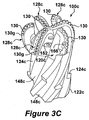
- FIGURE 3C is a schematic drawing showing one embodiment of a rotary drill bit in accordance with the present invention.
- Rotary drill bit 100c may be generally described as a fixed cutter drill bit.
- rotary drill bit 100c may also be described as a matrix drill bit steel body drill bit and/or a PDC drill bit.
- Rotary drill bit 100c includes bit body 120c with shank 122c.
- Shank 122c includes under gage blade portions 124c formed in the exterior thereof. Shank 122c may also include extensions of associated blades 128c. As shown in FIGURE 3C blades 128c may extend at an especially large spiral or angle relative to an associated bit rotational axis.
- One of the characteristics of rotary drill bits used with point-the-bit directional drilling systems may be relatively increased length of associated gage surfaces as compared with push-the-bit directional drilling systems.
- a longitudinal bore may extend through shank 122c and into bit body 120c.
- the longitudinal bore may be used to communicate drilling fluids from an associated drilling string to one or more nozzles 152 disposed in bit body 120c.
- a plurality of cutter blades 128c may be disposed on the exterior of bit body 120c. Respective junk slots or fluid flow slots 148c may be formed between adjacent blades 128c. Each cutter blade 128c may include a plurality of cutters 130g. For some applications cutters 130g may also be described as "cutting inserts”. Cutters 130g may be formed from very hard materials associated with forming a wellbore in a downhole formation.
- the exterior portions of bit body 120c opposite from shank 122c may be generally described as having a "bit face profile" as described with respect to rotary drill bit 100c.
- rotary drill bit 100c may also be described as a matrix drill bit and/or a PDC drill bit.
- Rotary drill bit 100c may include bit body 120c with shank 122c.
- the shank may include bit breaker slots (not shown) formed on the exterior thereof.
- Pin threaded connection (not shown) may be formed as an integral part of shank 122c extending from bit body 120c.
- Various types of threaded connections including but not limited to, API connections and premium threaded connections may be formed on the exterior of shank 122c.
- Blades 128c may also spiral or extend at an angle relative to the associated bit rotational axis.
- bit body 120c may be formed in part from a matrix of very hard materials associated with rotary drill bits.
- blades 128c may be machined from various metal alloys satisfactory for use in drilling wellbores in downhole formations. Examples ofmatrix type drill bits are shown in U.S. Patents 4696354 and 5099929 .
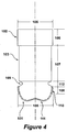
- FIGURE 4 is a side view of a rotary drill bit of the present invention.
- Rotary drill bit 100 has cutting section 101, heel section 102 and clearance section 103.
- Cutting section 101 is joined to clearance section 103 via neck section 109, wherein neck section 109 has a smaller outside diameter than clearance section 103.
- Cutting section 101 may have shallow cone profile 111 and aggressive gage cutters 110.
- Cutting section 101 may have six blades with PDC cutters positioned thereon.
- Clearance section 103 may have three blades with a high spiral pattern. Heel section 102 may also have three blades with a high spiral pattern.
- the blades of heel section 102 may be full gage 105 while the blades of the clearance section 103 may have an outside diameter less than full gage 105. Any number of blades may be used in the cutting, clearance and heel sections, respectively.
- heel section 102 may have three blades that may be 5-8 cm (2-3 inches) wide with a high spiral. Also, the outside diameter of the blades may have full gage 105 of about 17.1 cm (about 6.75 inches). Clearance section 103 may also have three blades about 5-8 cm (about 2-3 inches) wide with a high spiral. The outside diameter of the blades in clearance section 103 may be less than about 17.1 cm (about 6.75 inches), in particular, about 17 cm (about 6.6875 inches). Neck section 109 may have an outside diameter about 15 cm (about 6.00 inches). At aggressive gage cutters 110, cutting section 101 may have full gage 105 diameter of about 17.1 cm (about 6.75 inches).
- Heel section 102 may be about 5-10 cm (about 2-4 inches) in height 106, clearance section 103 may be about 13-18 cm (about 5-7 inches) in height 107, neck section 109 may be about 5-8 cm (about 2-3 inches) in height 112, and aggressive gage cutters 110 may be about 3-5 cm (about 1-3 inches) in height 108.
- the bit may be designed so as to reduce the required side force needed to steer the bit.
- Three aspects may be considered for the design: a shallow cone and an aggressive shoulder and gage; less contact area of the gage pad with the wall; and less stress level in the top of the sleeve (around the fulcrum point) by increasing the contact area or reducing the contact force.
- FIGURE 5A is a schematic drawing showing rotary drill bit 100 not forming part of the invention as claimed.
- Rotary drill bit 100 may include bit body 120 having a plurality of blades 128 with respective junk slots or fluid flow paths 140 formed therebetween.
- a plurality of cutting elements 130 may be disposed on the exterior portions of each blade 128.
- Each blade 128 may include respective gage surface or gage portion 154.
- Gage surface 154 may be an active gage and/or a passive gage.
- Respective gage cutter 131 may be disposed on each blade 128.
- a plurality of impact arrestors 142 may also be disposed on each blade 128. Additional information concerning impact arrestors may be found in U.S.
- Rotary drill bit 100 may also comprise heel blades 115, wherein the outside diameter of heel blades 115 approximately equal to the outside diameter of gage portion 154. Clearance section 103 is positioned between heel blades 115 and gage portion 154. Heel blades 115 have a high spiral, meaning that they twist around rotary drill bit 100 at a fairly high angle relative to the longitudinal central axis of the bit.
- FIGURE 5B is a schematic drawing showing rotary drill bit 100, similar to that illustrated in FIGURE 5A and being an embodiment of the present invention.
- Rotary drill bit 100 may include bit body 120 having a plurality of blades 128 with respective junk slots or fluid flow paths 140 formed therebetween.
- a plurality of cutting elements 130 may be disposed on the exterior portions of each blade 128.
- Each blade 128 may include respective gage surface or gage portion 154.
- Respective gage cutter 131 may be disposed on each blade 128.
- a plurality of impact arrestors 142 may also be disposed on each blade 128.
- Clearance section 103 is positioned between heel blades 115 and gage cutter 131. Blades 128 from the cutter section extend into the clearance section 103, but in clearance section 103, the blades have a smaller diameter, so as to allow the clearance section to extend all the way to gage cutter 131.
- Rotary drill bit 100 also comprises heel blades 115, wherein the outside diameter of heel blades 115 approximately equal to the outside diameter of gage portion 154. Heel blades 115 have a high spiral, meaning that they twist around rotary drill bit 100 at a fairly high angle relative to the longitudinal central axis of the bit.
- the bit face profile for rotary drill bit 100e as shown in FIGURES 6A and 6B may include recessed portion or cone shaped section 132e formed on the end of rotary drill bit 100e opposite from shank 122e.
- Each blade 128e may include respective nose 134e which defines in part an extreme end of rotary drill bit 100e opposite from shank 122e.
- Cone section 132e may extend inward from respective noses 134e toward bit rotational axis 104e.
- a plurality of cutting elements 130i may be disposed on portions of each blade 128e between respective nose 134e and rotational axis 104e. Cutters 130i may be referred to as "inner cutters”.
- Each blade 128e may also be described as having respective shoulder 136e extending outward from respective nose 134e.
- a plurality of cutter elements 130s may be disposed on each shoulder 136e.
- Cutting elements 130s may sometimes be referred to as "shoulder cutters.”
- Shoulder 136e and associated shoulder cutters 130s cooperate with each other to form portions of the bit face profile of rotary drill bit 100e extending outward from cone shaped section 132e.
- Gage cutters 130g and associated portions of each blade 128e form portions of the bit face profile of rotary drill bit 100e extending from shoulder cutters 130s.
- each blade 128e may include active gage portion 138 and passive gage portion 139.
- Various types of hardfacing and/or other hard materials may be disposed on each active gage portion 138.
- Each active gage portion 138 may include a positive taper angle 158 as shown in FIGURE 6B .
- Each passive gage portion may include respective positive taper angle 159a as shown in FIGURE 6B .
- the drill bit illustrated in FIGURES 6A and 6B also has heel section 102 with full gage 105 blades. Depending on the taper angle, the blades of heel section 102 may serves as the fulcrum point for taking the kick-off load from the side wall of the wellbore.
- Forming passive gage 139 with optimum negative taper angle 159b may result in contact between portions of passive gage 139 and adjacent portions of a wellbore to provide a fulcrum point to direct or guide rotary drill bit 100e during formation of a directional wellbore.
- the size of negative taper angle 159b may be limited to prevent undesired contact between passive gage 139 and adjacent portions of sidewall 63 during drilling of a vertical or straight hole segments of a wellbore. Steerability and controllability may be optimized by adjusting the length of passive gages with negative taper angles.
- forming a passive gage with a negative taper angle on a rotary drill bit may allow reducing the bend length of an associated rotary drill bit steering unit.
- the length of a bend subassembly included as part of the directional steering unit may be reduced as a result of having a rotary drill bit with an increased length in combination with a passive gage having a negative taper angle.
- a passive gage having a negative taper angle may facilitate tilting of an associated rotary drill bit during kick off drilling.
- Installing one or more gage cutters at optimum locations on an active gage portion and/or passive gage portion of a rotary drill bit may also serve to remove formation materials from the inside diameter of an associated wellbore during a directional drilling phase. These gage cutters may not contact the sidewall or inside diameter of a wellbore while drilling a vertical segment or straight hole segment of the directional wellbore.
- Passive gage 139 with an appropriate negative taper angle 159b and an optimum length may contact sidewall 63 during formation of an equilibrium portion and/or kick off portion of a wellbore. Such contact may substantially improve steerability and controllability of a rotary drill bit.
- Multiple tapered gage portions and/or variable tapered gage portions may be satisfactorily used with both point-the-bit and push-the-bit directional drilling systems.
- FIGURES 7A and 7B illustrate a bit of the present invention similar to the one illustrated with reference to FIGURES 6A and 6B , except that this bit does not have a taper angle or active gage portion 138. Rather, the bit has clearance section 103 that has a constant diameter from immediately adjacent to gage cutters 130g to immediately adjacent heel section 102. Bit may also have neck section 109 between clearance section 103 and heel section 102.
Landscapes
- Engineering & Computer Science (AREA)
- Geology (AREA)
- Life Sciences & Earth Sciences (AREA)
- Mining & Mineral Resources (AREA)
- Physics & Mathematics (AREA)
- Environmental & Geological Engineering (AREA)
- Fluid Mechanics (AREA)
- General Life Sciences & Earth Sciences (AREA)
- Geochemistry & Mineralogy (AREA)
- Mechanical Engineering (AREA)
- Processing Of Stones Or Stones Resemblance Materials (AREA)
- Earth Drilling (AREA)
- Drilling Tools (AREA)
Claims (8)
Applications Claiming Priority (2)
| Application Number | Priority Date | Filing Date | Title |
|---|---|---|---|
| US88792407P | 2007-02-02 | 2007-02-02 | |
| PCT/US2008/052798 WO2008097843A2 (en) | 2007-02-02 | 2008-02-01 | Rotary drill bit steerable system and method |
Publications (3)
| Publication Number | Publication Date |
|---|---|
| EP2118429A2 EP2118429A2 (de) | 2009-11-18 |
| EP2118429A4 EP2118429A4 (de) | 2014-07-09 |
| EP2118429B1 true EP2118429B1 (de) | 2016-04-13 |
Family
ID=39682345
Family Applications (1)
| Application Number | Title | Priority Date | Filing Date |
|---|---|---|---|
| EP08728825.4A Not-in-force EP2118429B1 (de) | 2007-02-02 | 2008-02-01 | Lenksystem und -verfahren für einen drehbohrer |
Country Status (4)
| Country | Link |
|---|---|
| US (1) | US8172010B2 (de) |
| EP (1) | EP2118429B1 (de) |
| CA (1) | CA2675670C (de) |
| WO (1) | WO2008097843A2 (de) |
Families Citing this family (13)
| Publication number | Priority date | Publication date | Assignee | Title |
|---|---|---|---|---|
| US8869919B2 (en) * | 2007-09-06 | 2014-10-28 | Smith International, Inc. | Drag bit with utility blades |
| US8127869B2 (en) | 2009-09-28 | 2012-03-06 | Baker Hughes Incorporated | Earth-boring tools, methods of making earth-boring tools and methods of drilling with earth-boring tools |
| US8978787B2 (en) * | 2012-01-12 | 2015-03-17 | Baker Hughes Incorporated | Turbine driven reaming bit with blades and cutting structure extending into concave nose |
| US9080390B2 (en) | 2012-01-12 | 2015-07-14 | Baker Hughes Incorporated | Turbine driven reaming bit with profile limiting torque fluctuation |
| US8973685B2 (en) | 2012-01-12 | 2015-03-10 | Baker Hughes Incorporated | Turbine driven reaming bit with stability and cutting efficiency features |
| US9970235B2 (en) | 2012-10-15 | 2018-05-15 | Bertrand Lacour | Rotary steerable drilling system for drilling a borehole in an earth formation |
| CN104594807A (zh) * | 2015-01-27 | 2015-05-06 | 青冈庆春油田机械制造有限公司 | 铸造螺旋刮刀刀翼 |
| WO2017172563A1 (en) | 2016-03-31 | 2017-10-05 | Schlumberger Technology Corporation | Equipment string communication and steering |
| CN108798530A (zh) * | 2017-05-03 | 2018-11-13 | 史密斯国际有限公司 | 钻头主体构造 |
| US11332980B2 (en) * | 2017-09-29 | 2022-05-17 | Baker Hughes Holdings Llc | Earth-boring tools having a gauge insert configured for reduced bit walk and method of drilling with same |
| PL3617439T3 (pl) * | 2018-08-30 | 2021-12-06 | Sandvik Mining And Construction Tools Ab | Wiertnicze narzędzie z zakrzywionymi rowkami dla szlamu |
| US12031383B2 (en) * | 2019-03-07 | 2024-07-09 | Halliburton Energy Services, Inc. | Shaped cutter arrangements |
| JP2023514821A (ja) | 2020-02-28 | 2023-04-11 | テキサス メディカル センター | 癒着阻止および組織治癒向上のための噴霧可能刺激応答性マイクロヒドロゲル |
Family Cites Families (16)
| Publication number | Priority date | Publication date | Assignee | Title |
|---|---|---|---|---|
| US3825083A (en) * | 1972-02-02 | 1974-07-23 | Christensen Diamond Prod Co | Drill bit and stabilizer combination |
| US4640375A (en) * | 1982-11-22 | 1987-02-03 | Nl Industries, Inc. | Drill bit and cutter therefor |
| DE3566566D1 (en) * | 1984-10-11 | 1989-01-05 | Diamant Boart Sa | Stabilizer |
| GB2212091B (en) * | 1987-11-12 | 1992-01-22 | Boart Hardmetals | Drilling equipment |
| US5004057A (en) * | 1988-01-20 | 1991-04-02 | Eastman Christensen Company | Drill bit with improved steerability |
| US4941538A (en) * | 1989-09-20 | 1990-07-17 | Hughes Tool Company | One-piece drill bit with improved gage design |
| US6123160A (en) * | 1997-04-02 | 2000-09-26 | Baker Hughes Incorporated | Drill bit with gage definition region |
| US6206117B1 (en) * | 1997-04-02 | 2001-03-27 | Baker Hughes Incorporated | Drilling structure with non-axial gage |
| US6173797B1 (en) * | 1997-09-08 | 2001-01-16 | Baker Hughes Incorporated | Rotary drill bits for directional drilling employing movable cutters and tandem gage pad arrangement with active cutting elements and having up-drill capability |
| US6138780A (en) * | 1997-09-08 | 2000-10-31 | Baker Hughes Incorporated | Drag bit with steel shank and tandem gage pads |
| US6321862B1 (en) * | 1997-09-08 | 2001-11-27 | Baker Hughes Incorporated | Rotary drill bits for directional drilling employing tandem gage pad arrangement with cutting elements and up-drill capability |
| US6688410B1 (en) * | 2000-06-07 | 2004-02-10 | Smith International, Inc. | Hydro-lifter rock bit with PDC inserts |
| US7308955B2 (en) * | 2005-03-22 | 2007-12-18 | Reedhycalog Uk Limited | Stabilizer arrangement |
| GB2443125B (en) * | 2005-08-08 | 2012-02-08 | Halliburton Energy Serv Inc | Computer-implemented methods to design a rotary drill bit with a desired bit walk rate |
| ATE414212T1 (de) * | 2006-01-18 | 2008-11-15 | Omni Oil Technologies | Bohrlochräumer |
| US20100038141A1 (en) * | 2007-08-15 | 2010-02-18 | Schlumberger Technology Corporation | Compliantly coupled gauge pad system with movable gauge pads |
-
2008
- 2008-02-01 US US12/525,346 patent/US8172010B2/en not_active Expired - Fee Related
- 2008-02-01 WO PCT/US2008/052798 patent/WO2008097843A2/en not_active Ceased
- 2008-02-01 EP EP08728825.4A patent/EP2118429B1/de not_active Not-in-force
- 2008-02-01 CA CA2675670A patent/CA2675670C/en not_active Expired - Fee Related
Also Published As
| Publication number | Publication date |
|---|---|
| EP2118429A2 (de) | 2009-11-18 |
| US8172010B2 (en) | 2012-05-08 |
| WO2008097843A2 (en) | 2008-08-14 |
| US20090321139A1 (en) | 2009-12-31 |
| CA2675670A1 (en) | 2008-08-14 |
| WO2008097843A3 (en) | 2008-11-06 |
| EP2118429A4 (de) | 2014-07-09 |
| CA2675670C (en) | 2015-12-08 |
Similar Documents
| Publication | Publication Date | Title |
|---|---|---|
| EP2118429B1 (de) | Lenksystem und -verfahren für einen drehbohrer | |
| CA2590439C (en) | Drill bit with asymmetric gage pad configuration | |
| CA2427254C (en) | Fixed blade fixed cutter hole opener | |
| US6308790B1 (en) | Drag bits with predictable inclination tendencies and behavior | |
| US7621348B2 (en) | Drag bits with dropping tendencies and methods for making the same | |
| US5937958A (en) | Drill bits with predictable walk tendencies | |
| US8356679B2 (en) | Rotary drill bit with gage pads having improved steerability and reduced wear | |
| CA2707602C (en) | Apparatus and methods to optimize fluid flow and performance of downhole drilling equipment | |
| CA2588504A1 (en) | Drill bit with plural set and single set blade configuration | |
| US9644428B2 (en) | Drill bit with a hybrid cutter profile | |
| US20190316420A1 (en) | Earth boring tools with pockets having cutting elements disposed therein trailing rotationally leading faces of blades and related methods | |
| US8453767B2 (en) | Angular offset PDC cutting structures | |
| GB2438717A (en) | Drill Bit |
Legal Events
| Date | Code | Title | Description |
|---|---|---|---|
| PUAI | Public reference made under article 153(3) epc to a published international application that has entered the european phase |
Free format text: ORIGINAL CODE: 0009012 |
|
| 17P | Request for examination filed |
Effective date: 20090828 |
|
| AK | Designated contracting states |
Kind code of ref document: A2 Designated state(s): AT BE BG CH CY CZ DE DK EE ES FI FR GB GR HR HU IE IS IT LI LT LU LV MC MT NL NO PL PT RO SE SI SK TR |
|
| RIN1 | Information on inventor provided before grant (corrected) |
Inventor name: STRACHAN, MICHAEL, J. |
|
| DAX | Request for extension of the european patent (deleted) | ||
| A4 | Supplementary search report drawn up and despatched |
Effective date: 20140612 |
|
| RIC1 | Information provided on ipc code assigned before grant |
Ipc: E21B 17/10 20060101ALI20140605BHEP Ipc: E21B 10/26 20060101AFI20140605BHEP Ipc: E21B 10/42 20060101ALI20140605BHEP |
|
| 17Q | First examination report despatched |
Effective date: 20141024 |
|
| GRAP | Despatch of communication of intention to grant a patent |
Free format text: ORIGINAL CODE: EPIDOSNIGR1 |
|
| INTG | Intention to grant announced |
Effective date: 20151013 |
|
| GRAS | Grant fee paid |
Free format text: ORIGINAL CODE: EPIDOSNIGR3 |
|
| GRAA | (expected) grant |
Free format text: ORIGINAL CODE: 0009210 |
|
| AK | Designated contracting states |
Kind code of ref document: B1 Designated state(s): AT BE BG CH CY CZ DE DK EE ES FI FR GB GR HR HU IE IS IT LI LT LU LV MC MT NL NO PL PT RO SE SI SK TR |
|
| REG | Reference to a national code |
Ref country code: GB Ref legal event code: FG4D |
|
| REG | Reference to a national code |
Ref country code: AT Ref legal event code: REF Ref document number: 790388 Country of ref document: AT Kind code of ref document: T Effective date: 20160415 Ref country code: CH Ref legal event code: EP |
|
| REG | Reference to a national code |
Ref country code: IE Ref legal event code: FG4D |
|
| REG | Reference to a national code |
Ref country code: DE Ref legal event code: R096 Ref document number: 602008043501 Country of ref document: DE |
|
| REG | Reference to a national code |
Ref country code: LT Ref legal event code: MG4D |
|
| REG | Reference to a national code |
Ref country code: AT Ref legal event code: MK05 Ref document number: 790388 Country of ref document: AT Kind code of ref document: T Effective date: 20160413 |
|
| REG | Reference to a national code |
Ref country code: NL Ref legal event code: MP Effective date: 20160413 |
|
| PG25 | Lapsed in a contracting state [announced via postgrant information from national office to epo] |
Ref country code: FI Free format text: LAPSE BECAUSE OF FAILURE TO SUBMIT A TRANSLATION OF THE DESCRIPTION OR TO PAY THE FEE WITHIN THE PRESCRIBED TIME-LIMIT Effective date: 20160413 Ref country code: LT Free format text: LAPSE BECAUSE OF FAILURE TO SUBMIT A TRANSLATION OF THE DESCRIPTION OR TO PAY THE FEE WITHIN THE PRESCRIBED TIME-LIMIT Effective date: 20160413 Ref country code: NO Free format text: LAPSE BECAUSE OF FAILURE TO SUBMIT A TRANSLATION OF THE DESCRIPTION OR TO PAY THE FEE WITHIN THE PRESCRIBED TIME-LIMIT Effective date: 20160713 Ref country code: NL Free format text: LAPSE BECAUSE OF FAILURE TO SUBMIT A TRANSLATION OF THE DESCRIPTION OR TO PAY THE FEE WITHIN THE PRESCRIBED TIME-LIMIT Effective date: 20160413 Ref country code: PL Free format text: LAPSE BECAUSE OF FAILURE TO SUBMIT A TRANSLATION OF THE DESCRIPTION OR TO PAY THE FEE WITHIN THE PRESCRIBED TIME-LIMIT Effective date: 20160413 |
|
| PG25 | Lapsed in a contracting state [announced via postgrant information from national office to epo] |
Ref country code: GR Free format text: LAPSE BECAUSE OF FAILURE TO SUBMIT A TRANSLATION OF THE DESCRIPTION OR TO PAY THE FEE WITHIN THE PRESCRIBED TIME-LIMIT Effective date: 20160714 Ref country code: HR Free format text: LAPSE BECAUSE OF FAILURE TO SUBMIT A TRANSLATION OF THE DESCRIPTION OR TO PAY THE FEE WITHIN THE PRESCRIBED TIME-LIMIT Effective date: 20160413 Ref country code: PT Free format text: LAPSE BECAUSE OF FAILURE TO SUBMIT A TRANSLATION OF THE DESCRIPTION OR TO PAY THE FEE WITHIN THE PRESCRIBED TIME-LIMIT Effective date: 20160816 Ref country code: ES Free format text: LAPSE BECAUSE OF FAILURE TO SUBMIT A TRANSLATION OF THE DESCRIPTION OR TO PAY THE FEE WITHIN THE PRESCRIBED TIME-LIMIT Effective date: 20160413 Ref country code: LV Free format text: LAPSE BECAUSE OF FAILURE TO SUBMIT A TRANSLATION OF THE DESCRIPTION OR TO PAY THE FEE WITHIN THE PRESCRIBED TIME-LIMIT Effective date: 20160413 Ref country code: AT Free format text: LAPSE BECAUSE OF FAILURE TO SUBMIT A TRANSLATION OF THE DESCRIPTION OR TO PAY THE FEE WITHIN THE PRESCRIBED TIME-LIMIT Effective date: 20160413 Ref country code: SE Free format text: LAPSE BECAUSE OF FAILURE TO SUBMIT A TRANSLATION OF THE DESCRIPTION OR TO PAY THE FEE WITHIN THE PRESCRIBED TIME-LIMIT Effective date: 20160413 |
|
| PG25 | Lapsed in a contracting state [announced via postgrant information from national office to epo] |
Ref country code: BE Free format text: LAPSE BECAUSE OF FAILURE TO SUBMIT A TRANSLATION OF THE DESCRIPTION OR TO PAY THE FEE WITHIN THE PRESCRIBED TIME-LIMIT Effective date: 20160413 Ref country code: IT Free format text: LAPSE BECAUSE OF FAILURE TO SUBMIT A TRANSLATION OF THE DESCRIPTION OR TO PAY THE FEE WITHIN THE PRESCRIBED TIME-LIMIT Effective date: 20160413 |
|
| REG | Reference to a national code |
Ref country code: DE Ref legal event code: R097 Ref document number: 602008043501 Country of ref document: DE |
|
| PG25 | Lapsed in a contracting state [announced via postgrant information from national office to epo] |
Ref country code: EE Free format text: LAPSE BECAUSE OF FAILURE TO SUBMIT A TRANSLATION OF THE DESCRIPTION OR TO PAY THE FEE WITHIN THE PRESCRIBED TIME-LIMIT Effective date: 20160413 Ref country code: CZ Free format text: LAPSE BECAUSE OF FAILURE TO SUBMIT A TRANSLATION OF THE DESCRIPTION OR TO PAY THE FEE WITHIN THE PRESCRIBED TIME-LIMIT Effective date: 20160413 Ref country code: SK Free format text: LAPSE BECAUSE OF FAILURE TO SUBMIT A TRANSLATION OF THE DESCRIPTION OR TO PAY THE FEE WITHIN THE PRESCRIBED TIME-LIMIT Effective date: 20160413 Ref country code: DK Free format text: LAPSE BECAUSE OF FAILURE TO SUBMIT A TRANSLATION OF THE DESCRIPTION OR TO PAY THE FEE WITHIN THE PRESCRIBED TIME-LIMIT Effective date: 20160413 Ref country code: RO Free format text: LAPSE BECAUSE OF FAILURE TO SUBMIT A TRANSLATION OF THE DESCRIPTION OR TO PAY THE FEE WITHIN THE PRESCRIBED TIME-LIMIT Effective date: 20160413 |
|
| PLBE | No opposition filed within time limit |
Free format text: ORIGINAL CODE: 0009261 |
|
| STAA | Information on the status of an ep patent application or granted ep patent |
Free format text: STATUS: NO OPPOSITION FILED WITHIN TIME LIMIT |
|
| 26N | No opposition filed |
Effective date: 20170116 |
|
| PG25 | Lapsed in a contracting state [announced via postgrant information from national office to epo] |
Ref country code: SI Free format text: LAPSE BECAUSE OF FAILURE TO SUBMIT A TRANSLATION OF THE DESCRIPTION OR TO PAY THE FEE WITHIN THE PRESCRIBED TIME-LIMIT Effective date: 20160413 |
|
| REG | Reference to a national code |
Ref country code: DE Ref legal event code: R119 Ref document number: 602008043501 Country of ref document: DE |
|
| PG25 | Lapsed in a contracting state [announced via postgrant information from national office to epo] |
Ref country code: MC Free format text: LAPSE BECAUSE OF FAILURE TO SUBMIT A TRANSLATION OF THE DESCRIPTION OR TO PAY THE FEE WITHIN THE PRESCRIBED TIME-LIMIT Effective date: 20160413 |
|
| REG | Reference to a national code |
Ref country code: CH Ref legal event code: PL |
|
| GBPC | Gb: european patent ceased through non-payment of renewal fee |
Effective date: 20170201 |
|
| PG25 | Lapsed in a contracting state [announced via postgrant information from national office to epo] |
Ref country code: LI Free format text: LAPSE BECAUSE OF NON-PAYMENT OF DUE FEES Effective date: 20170228 Ref country code: CH Free format text: LAPSE BECAUSE OF NON-PAYMENT OF DUE FEES Effective date: 20170228 |
|
| REG | Reference to a national code |
Ref country code: IE Ref legal event code: MM4A |
|
| REG | Reference to a national code |
Ref country code: FR Ref legal event code: ST Effective date: 20171031 |
|
| PG25 | Lapsed in a contracting state [announced via postgrant information from national office to epo] |
Ref country code: LU Free format text: LAPSE BECAUSE OF NON-PAYMENT OF DUE FEES Effective date: 20170201 |
|
| PG25 | Lapsed in a contracting state [announced via postgrant information from national office to epo] |
Ref country code: FR Free format text: LAPSE BECAUSE OF NON-PAYMENT OF DUE FEES Effective date: 20170228 Ref country code: DE Free format text: LAPSE BECAUSE OF NON-PAYMENT OF DUE FEES Effective date: 20170901 |
|
| PG25 | Lapsed in a contracting state [announced via postgrant information from national office to epo] |
Ref country code: GB Free format text: LAPSE BECAUSE OF NON-PAYMENT OF DUE FEES Effective date: 20170201 Ref country code: IE Free format text: LAPSE BECAUSE OF NON-PAYMENT OF DUE FEES Effective date: 20170201 |
|
| PG25 | Lapsed in a contracting state [announced via postgrant information from national office to epo] |
Ref country code: MT Free format text: LAPSE BECAUSE OF NON-PAYMENT OF DUE FEES Effective date: 20170201 |
|
| PG25 | Lapsed in a contracting state [announced via postgrant information from national office to epo] |
Ref country code: HU Free format text: LAPSE BECAUSE OF FAILURE TO SUBMIT A TRANSLATION OF THE DESCRIPTION OR TO PAY THE FEE WITHIN THE PRESCRIBED TIME-LIMIT; INVALID AB INITIO Effective date: 20080201 |
|
| PG25 | Lapsed in a contracting state [announced via postgrant information from national office to epo] |
Ref country code: BG Free format text: LAPSE BECAUSE OF FAILURE TO SUBMIT A TRANSLATION OF THE DESCRIPTION OR TO PAY THE FEE WITHIN THE PRESCRIBED TIME-LIMIT Effective date: 20160413 |
|
| PG25 | Lapsed in a contracting state [announced via postgrant information from national office to epo] |
Ref country code: CY Free format text: LAPSE BECAUSE OF NON-PAYMENT OF DUE FEES Effective date: 20160413 |
|
| PG25 | Lapsed in a contracting state [announced via postgrant information from national office to epo] |
Ref country code: TR Free format text: LAPSE BECAUSE OF FAILURE TO SUBMIT A TRANSLATION OF THE DESCRIPTION OR TO PAY THE FEE WITHIN THE PRESCRIBED TIME-LIMIT Effective date: 20160413 |
|
| PG25 | Lapsed in a contracting state [announced via postgrant information from national office to epo] |
Ref country code: IS Free format text: LAPSE BECAUSE OF FAILURE TO SUBMIT A TRANSLATION OF THE DESCRIPTION OR TO PAY THE FEE WITHIN THE PRESCRIBED TIME-LIMIT Effective date: 20160813 |