EP2118469B1 - Moteur à combustion - Google Patents
Moteur à combustion Download PDFInfo
- Publication number
- EP2118469B1 EP2118469B1 EP08707514.9A EP08707514A EP2118469B1 EP 2118469 B1 EP2118469 B1 EP 2118469B1 EP 08707514 A EP08707514 A EP 08707514A EP 2118469 B1 EP2118469 B1 EP 2118469B1
- Authority
- EP
- European Patent Office
- Prior art keywords
- mixing device
- combustion engine
- internal combustion
- compressor
- mixing
- Prior art date
- Legal status (The legal status is an assumption and is not a legal conclusion. Google has not performed a legal analysis and makes no representation as to the accuracy of the status listed.)
- Not-in-force
Links
Images

Classifications
-
- F—MECHANICAL ENGINEERING; LIGHTING; HEATING; WEAPONS; BLASTING
- F02—COMBUSTION ENGINES; HOT-GAS OR COMBUSTION-PRODUCT ENGINE PLANTS
- F02B—INTERNAL-COMBUSTION PISTON ENGINES; COMBUSTION ENGINES IN GENERAL
- F02B37/00—Engines characterised by provision of pumps driven at least for part of the time by exhaust
- F02B37/12—Control of the pumps
- F02B37/22—Control of the pumps by varying cross-section of exhaust passages or air passages, e.g. by throttling turbine inlets or outlets or by varying effective number of guide conduits
- F02B37/225—Control of the pumps by varying cross-section of exhaust passages or air passages, e.g. by throttling turbine inlets or outlets or by varying effective number of guide conduits air passages
-
- F—MECHANICAL ENGINEERING; LIGHTING; HEATING; WEAPONS; BLASTING
- F02—COMBUSTION ENGINES; HOT-GAS OR COMBUSTION-PRODUCT ENGINE PLANTS
- F02B—INTERNAL-COMBUSTION PISTON ENGINES; COMBUSTION ENGINES IN GENERAL
- F02B37/00—Engines characterised by provision of pumps driven at least for part of the time by exhaust
- F02B37/12—Control of the pumps
- F02B37/22—Control of the pumps by varying cross-section of exhaust passages or air passages, e.g. by throttling turbine inlets or outlets or by varying effective number of guide conduits
-
- F—MECHANICAL ENGINEERING; LIGHTING; HEATING; WEAPONS; BLASTING
- F02—COMBUSTION ENGINES; HOT-GAS OR COMBUSTION-PRODUCT ENGINE PLANTS
- F02M—SUPPLYING COMBUSTION ENGINES IN GENERAL WITH COMBUSTIBLE MIXTURES OR CONSTITUENTS THEREOF
- F02M26/00—Engine-pertinent apparatus for adding exhaust gases to combustion-air, main fuel or fuel-air mixture, e.g. by exhaust gas recirculation [EGR] systems
- F02M26/02—EGR systems specially adapted for supercharged engines
- F02M26/04—EGR systems specially adapted for supercharged engines with a single turbocharger
- F02M26/06—Low pressure loops, i.e. wherein recirculated exhaust gas is taken out from the exhaust downstream of the turbocharger turbine and reintroduced into the intake system upstream of the compressor
-
- F—MECHANICAL ENGINEERING; LIGHTING; HEATING; WEAPONS; BLASTING
- F02—COMBUSTION ENGINES; HOT-GAS OR COMBUSTION-PRODUCT ENGINE PLANTS
- F02M—SUPPLYING COMBUSTION ENGINES IN GENERAL WITH COMBUSTIBLE MIXTURES OR CONSTITUENTS THEREOF
- F02M26/00—Engine-pertinent apparatus for adding exhaust gases to combustion-air, main fuel or fuel-air mixture, e.g. by exhaust gas recirculation [EGR] systems
- F02M26/13—Arrangement or layout of EGR passages, e.g. in relation to specific engine parts or for incorporation of accessories
- F02M26/17—Arrangement or layout of EGR passages, e.g. in relation to specific engine parts or for incorporation of accessories in relation to the intake system
- F02M26/19—Means for improving the mixing of air and recirculated exhaust gases, e.g. venturis or multiple openings to the intake system
-
- F—MECHANICAL ENGINEERING; LIGHTING; HEATING; WEAPONS; BLASTING
- F02—COMBUSTION ENGINES; HOT-GAS OR COMBUSTION-PRODUCT ENGINE PLANTS
- F02M—SUPPLYING COMBUSTION ENGINES IN GENERAL WITH COMBUSTIBLE MIXTURES OR CONSTITUENTS THEREOF
- F02M29/00—Apparatus for re-atomising condensed fuel or homogenising fuel-air mixture
- F02M29/04—Apparatus for re-atomising condensed fuel or homogenising fuel-air mixture having screens, gratings, baffles or the like
-
- F—MECHANICAL ENGINEERING; LIGHTING; HEATING; WEAPONS; BLASTING
- F02—COMBUSTION ENGINES; HOT-GAS OR COMBUSTION-PRODUCT ENGINE PLANTS
- F02M—SUPPLYING COMBUSTION ENGINES IN GENERAL WITH COMBUSTIBLE MIXTURES OR CONSTITUENTS THEREOF
- F02M35/00—Combustion-air cleaners, air intakes, intake silencers, or induction systems specially adapted for, or arranged on, internal-combustion engines
- F02M35/10—Air intakes; Induction systems
- F02M35/10209—Fluid connections to the air intake system; their arrangement of pipes, valves or the like
- F02M35/10222—Exhaust gas recirculation [EGR]; Positive crankcase ventilation [PCV]; Additional air admission, lubricant or fuel vapour admission
-
- F—MECHANICAL ENGINEERING; LIGHTING; HEATING; WEAPONS; BLASTING
- F02—COMBUSTION ENGINES; HOT-GAS OR COMBUSTION-PRODUCT ENGINE PLANTS
- F02M—SUPPLYING COMBUSTION ENGINES IN GENERAL WITH COMBUSTIBLE MIXTURES OR CONSTITUENTS THEREOF
- F02M35/00—Combustion-air cleaners, air intakes, intake silencers, or induction systems specially adapted for, or arranged on, internal-combustion engines
- F02M35/10—Air intakes; Induction systems
- F02M35/10242—Devices or means connected to or integrated into air intakes; Air intakes combined with other engine or vehicle parts
- F02M35/10262—Flow guides, obstructions, deflectors or the like
-
- F—MECHANICAL ENGINEERING; LIGHTING; HEATING; WEAPONS; BLASTING
- F02—COMBUSTION ENGINES; HOT-GAS OR COMBUSTION-PRODUCT ENGINE PLANTS
- F02M—SUPPLYING COMBUSTION ENGINES IN GENERAL WITH COMBUSTIBLE MIXTURES OR CONSTITUENTS THEREOF
- F02M9/00—Carburettors having air or fuel-air mixture passage throttling valves other than of butterfly type; Carburettors having fuel-air mixing chambers of variable shape or position
- F02M9/02—Carburettors having air or fuel-air mixture passage throttling valves other than of butterfly type; Carburettors having fuel-air mixing chambers of variable shape or position having throttling valves, e.g. of piston shape, slidably arranged transversely to the passage
- F02M9/04—Carburettors having air or fuel-air mixture passage throttling valves other than of butterfly type; Carburettors having fuel-air mixing chambers of variable shape or position having throttling valves, e.g. of piston shape, slidably arranged transversely to the passage with throttling valves sliding in a plane inclined to the passage
-
- F—MECHANICAL ENGINEERING; LIGHTING; HEATING; WEAPONS; BLASTING
- F02—COMBUSTION ENGINES; HOT-GAS OR COMBUSTION-PRODUCT ENGINE PLANTS
- F02M—SUPPLYING COMBUSTION ENGINES IN GENERAL WITH COMBUSTIBLE MIXTURES OR CONSTITUENTS THEREOF
- F02M26/00—Engine-pertinent apparatus for adding exhaust gases to combustion-air, main fuel or fuel-air mixture, e.g. by exhaust gas recirculation [EGR] systems
- F02M26/13—Arrangement or layout of EGR passages, e.g. in relation to specific engine parts or for incorporation of accessories
- F02M26/14—Arrangement or layout of EGR passages, e.g. in relation to specific engine parts or for incorporation of accessories in relation to the exhaust system
- F02M26/15—Arrangement or layout of EGR passages, e.g. in relation to specific engine parts or for incorporation of accessories in relation to the exhaust system in relation to engine exhaust purifying apparatus
-
- F—MECHANICAL ENGINEERING; LIGHTING; HEATING; WEAPONS; BLASTING
- F02—COMBUSTION ENGINES; HOT-GAS OR COMBUSTION-PRODUCT ENGINE PLANTS
- F02M—SUPPLYING COMBUSTION ENGINES IN GENERAL WITH COMBUSTIBLE MIXTURES OR CONSTITUENTS THEREOF
- F02M26/00—Engine-pertinent apparatus for adding exhaust gases to combustion-air, main fuel or fuel-air mixture, e.g. by exhaust gas recirculation [EGR] systems
- F02M26/13—Arrangement or layout of EGR passages, e.g. in relation to specific engine parts or for incorporation of accessories
- F02M26/22—Arrangement or layout of EGR passages, e.g. in relation to specific engine parts or for incorporation of accessories with coolers in the recirculation passage
- F02M26/23—Layout, e.g. schematics
-
- Y—GENERAL TAGGING OF NEW TECHNOLOGICAL DEVELOPMENTS; GENERAL TAGGING OF CROSS-SECTIONAL TECHNOLOGIES SPANNING OVER SEVERAL SECTIONS OF THE IPC; TECHNICAL SUBJECTS COVERED BY FORMER USPC CROSS-REFERENCE ART COLLECTIONS [XRACs] AND DIGESTS
- Y02—TECHNOLOGIES OR APPLICATIONS FOR MITIGATION OR ADAPTATION AGAINST CLIMATE CHANGE
- Y02T—CLIMATE CHANGE MITIGATION TECHNOLOGIES RELATED TO TRANSPORTATION
- Y02T10/00—Road transport of goods or passengers
- Y02T10/10—Internal combustion engine [ICE] based vehicles
- Y02T10/12—Improving ICE efficiencies
Definitions
- the invention relates to an internal combustion engine according to the preamble of claim 1.
- a generic internal combustion engine is from the WO 2006/122306 A2 known.
- Turbochargers of such internal combustion engines are used to return large amounts of exhaust gas into the intake line of the engine over a wide operating range in order to meet the legally prescribed exhaust gas limit values. This is carried out in the current state of the art via a so-called high-pressure exhaust gas recirculation. In contrast, the low-pressure side exhaust gas recirculation has a greater potential. In this case, the exhaust gas is removed behind the turbine after exiting the diesel particulate filter and returned via a control valve and optionally via a cooler in the fresh air section in front of the compressor of the exhaust gas turbocharger.
- a specific mixing device in the intake manifold to achieve the fullest possible mixing of the recirculated exhaust gas with the fresh air.
- This mixing device is arranged in the intake line, viewed in the fresh air flow direction, after the exhaust gas mixing opening and before the compressor inlet.
- the Indian Fig. 1 shown turbocharger 1 has a turbine 4 with a turbine housing 14 arranged in a turbine housing 14. This turbine wheel 14 is connected via a rotor shaft 15 to a compressor wheel 6 of a compressor 5 arranged in a compressor housing 7.
- An exhaust gas recirculation line 3 from an engine 2 leads via a control valve 19 and a radiator 20 through an exhaust gas mixing opening 12 into an intake line 10 of the engine 2.
- a mixing device 18 in particular a flower mixer, is arranged in front of the compressor inlet 11 by means of a mixer holder 23 ,
- the radial portion of the flow direction S of the air compressed in the diffuser 8 by the compressor wheel 6 is here indicated by an arrow S.
- a supply line 16 from the compressor outlet 9 to the engine 2 and an exhaust pipe 17 from the engine 2 to the turbine housing 13 are also shown.
- the exhaust gas AG is passed through the Abgaseinmischö réelle 12 into the intake passage 10.
- the exhaust gas AG meets the fresh air FL, which are then mixed together in the flow direction of the fresh air FL by the mixing device 18, in particular the flower mixer. After almost complete mixing of the two streams, the mixture flows through the compressor inlet 11 into the diffuser 8.
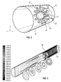
- Fig. 2 is the mixing device 18, in particular the flower mixer shown.
- the flower mixer has in the middle a streamlined core body 25 and a surrounding this core body 25 annular mixer body 21 on which flow baffles / mixer plates 22 are arranged.
- mixer plates 22 are significantly involved in the most complete possible mixing. For this purpose, it is necessary that the core flow located in the line center radially to the outside and located at the outer edge Side flow are directed radially inward.
- a meander-shaped design of the mixer plates alternately a radial flow component is generated inwardly and outwardly, whereby an enlargement of the boundary surface of both flows and thus a better mixing comes about.
- Fig. 3 represents the numerical simulation of the mixing of two different streams of a arranged in the intake manifold 10 flower mixer 18. It can be seen that before the flower mixer two distinct gas streams with different temperatures are available. Inside the pipe is the warmer recirculated exhaust gas flow at about 473 K and at the outer edge of the colder intake air flow with about 297 K can be found. Immediately after the mixer, a rapid temperature equalization of both flows takes place, so that average temperatures in the range of about 350 K to 390 K arise.
Landscapes
- Engineering & Computer Science (AREA)
- Chemical & Material Sciences (AREA)
- Combustion & Propulsion (AREA)
- Mechanical Engineering (AREA)
- General Engineering & Computer Science (AREA)
- Supercharger (AREA)
- Exhaust-Gas Circulating Devices (AREA)
Claims (4)
- Moteur à combustion interne (2) comprenant un turbocompresseur (1), comprenant au moins une conduite de recirculation de gaz d'échappement (3) qui pénètre par le biais d'une ouverture de mélange de gaz d'échappement (12) dans une conduite d'admission (10) du moteur à combustion interne (2) ; comprenant- une turbine (4) ;- un compresseur (5) ;
qui est connecté par entraînement à la turbine (4), et
qui présente une roue de compresseur (6), qui est disposée dans un boîtier de compresseur (7) dans lequel débouche la conduite d'admission (10) par le biais d'une entrée de compresseur (11) ; et- un dispositif de mélange (18),caractérisé en ce que- le dispositif de mélange (18) est disposé dans la conduite d'admission (10), vu dans la direction d'écoulement d'air frais (FL), après l'ouverture de mélange de gaz d'échappement (12) et avant l'entrée de compresseur (11),- le dispositif de mélange (18) présente, radialement à l'intérieur, des tôles directrices en méandres, pour guider un écoulement auxiliaire extérieur,- le dispositif de mélange (18) guide l'écoulement de coeur vers l'extérieur et l'écoulement auxiliaire vers l'intérieur,- le dispositif de mélange (18) est réalisé sous forme d'un mélangeur en forme de fleur. - Moteur à combustion interne selon la revendication 1, caractérisé en ce que le dispositif de mélange (18) présente un corps d'écoulement central (25) pour accélérer un écoulement de coeur.
- Moteur à combustion interne selon la revendication 2, caractérisé en ce que le dispositif de mélange (18) conduit l'écoulement de coeur interne radialement vers l'extérieur.
- Moteur à combustion interne selon l'une quelconque des revendications 1 à 3, caractérisé en ce que le dispositif de mélange (18) est fixé par une région extérieure (27) par des tôles directrices et/ou par des nervures (26) au niveau du corps de mélange annulaire (21) dans la conduite d'admission (10).
Applications Claiming Priority (2)
| Application Number | Priority Date | Filing Date | Title |
|---|---|---|---|
| DE102007005702 | 2007-02-05 | ||
| PCT/EP2008/000833 WO2008095658A1 (fr) | 2007-02-05 | 2008-02-01 | Turbocompresseur |
Publications (2)
| Publication Number | Publication Date |
|---|---|
| EP2118469A1 EP2118469A1 (fr) | 2009-11-18 |
| EP2118469B1 true EP2118469B1 (fr) | 2016-03-30 |
Family
ID=39343477
Family Applications (1)
| Application Number | Title | Priority Date | Filing Date |
|---|---|---|---|
| EP08707514.9A Not-in-force EP2118469B1 (fr) | 2007-02-05 | 2008-02-01 | Moteur à combustion |
Country Status (6)
| Country | Link |
|---|---|
| US (1) | US8499558B2 (fr) |
| EP (1) | EP2118469B1 (fr) |
| JP (1) | JP2010518298A (fr) |
| KR (1) | KR20090116717A (fr) |
| CN (1) | CN101578439B (fr) |
| WO (1) | WO2008095658A1 (fr) |
Families Citing this family (10)
| Publication number | Priority date | Publication date | Assignee | Title |
|---|---|---|---|---|
| CN102317592B (zh) * | 2009-03-03 | 2014-04-16 | 博格华纳公司 | 涡轮增压器 |
| DE102009034653A1 (de) * | 2009-07-24 | 2011-01-27 | Mahle International Gmbh | Brennkraftmaschine und Frischluftanlage |
| JP5813017B2 (ja) * | 2010-02-17 | 2015-11-17 | ボーグワーナー インコーポレーテッド | ターボチャージャ |
| JP5747483B2 (ja) * | 2010-11-16 | 2015-07-15 | 株式会社Ihi | 低圧ループegr装置 |
| JP5047352B2 (ja) | 2010-12-28 | 2012-10-10 | 三菱重工業株式会社 | 排気ターボ過給機のハウジング構造 |
| JP5825791B2 (ja) * | 2011-01-19 | 2015-12-02 | 三菱重工業株式会社 | 過給機およびこれを備えたディーゼル機関 |
| WO2016147310A1 (fr) * | 2015-03-17 | 2016-09-22 | 三菱重工業株式会社 | Rotor de machine rotative, compresseur, turbocompresseur et procédé de fabrication de rotor de machine rotative |
| US9617933B2 (en) * | 2015-08-03 | 2017-04-11 | Borgwarner Inc. | Low pressure EGR control using throttling |
| JP6041943B2 (ja) * | 2015-08-12 | 2016-12-14 | 三菱重工業株式会社 | 舶用ディーゼル機関用過給機およびこれを備えた舶用ディーゼル機関 |
| US20190040824A1 (en) * | 2017-08-03 | 2019-02-07 | GM Global Technology Operations LLC | Long route-egr connection for compressor inlet swirl control |
Citations (1)
| Publication number | Priority date | Publication date | Assignee | Title |
|---|---|---|---|---|
| WO2006122306A2 (fr) * | 2005-05-11 | 2006-11-16 | Borgwarner Inc. | Systeme de gestion d'air pour moteur |
Family Cites Families (28)
| Publication number | Priority date | Publication date | Assignee | Title |
|---|---|---|---|---|
| US4401269A (en) * | 1980-09-26 | 1983-08-30 | United Technologies Corporation | Lobe mixer for gas turbine engine |
| GB2160265A (en) * | 1984-06-12 | 1985-12-18 | Rolls Royce | Turbofan exhaust mixers |
| DE3529543A1 (de) * | 1985-08-17 | 1987-02-26 | Daimler Benz Ag | Verbindungsleitung zwischen einem verdichter eines am abgaskruemmer einer brennkraftmaschine angeflanschten abgasturboladers und einem saugrohr |
| DE4213047A1 (de) | 1992-04-21 | 1993-10-28 | Kuehnle Kopp Kausch Ag | Verdichter mit einer Einrichtung zum Beeinflussen der Hauptströmung im Verdichter |
| AU6769598A (en) * | 1997-03-31 | 1998-10-22 | Allied-Signal Inc. | Turbocharger integral fluid temperature management system |
| US5771868A (en) * | 1997-07-03 | 1998-06-30 | Turbodyne Systems, Inc. | Turbocharging systems for internal combustion engines |
| DE10007243C1 (de) * | 2000-02-17 | 2001-04-26 | Daimler Chrysler Ag | Abgasrückführvorrichtung |
| US6427671B1 (en) * | 2000-07-17 | 2002-08-06 | Caterpillar Inc. | Exhaust gas recirculation mixer apparatus and method |
| US6425382B1 (en) * | 2001-01-09 | 2002-07-30 | Cummins Engine Company, Inc. | Air-exhaust mixer assembly |
| JP4743465B2 (ja) * | 2001-04-19 | 2011-08-10 | 株式会社Ihi | ジェットエンジン用ローブミキサー |
| CA2455075C (fr) * | 2001-08-06 | 2010-07-20 | Eric Ashworth | Mecanisme de linearisation de propulsion |
| SE524706C2 (sv) * | 2002-06-03 | 2004-09-21 | Stt Emtec Ab | Anordning och förfarande för rening av avgaser samt användning av anordningen vid en diselmotor |
| JP3951951B2 (ja) * | 2003-04-03 | 2007-08-01 | トヨタ自動車株式会社 | 内燃機関の制御装置 |
| GB0308013D0 (en) * | 2003-04-07 | 2003-05-14 | Prodrive 2000 Ltd | Turbocharger |
| US6988365B2 (en) * | 2003-11-19 | 2006-01-24 | Southwest Research Institute | Dual loop exhaust gas recirculation system for diesel engines and method of operation |
| US6886544B1 (en) * | 2004-03-03 | 2005-05-03 | Caterpillar Inc | Exhaust gas venturi injector for an exhaust gas recirculation system |
| US7032578B2 (en) * | 2004-09-21 | 2006-04-25 | International Engine Intellectual Property Company, Llc | Venturi mixing system for exhaust gas recirculation (EGR) |
| US7117843B2 (en) * | 2004-10-07 | 2006-10-10 | International Engine Intellectual Property Company, Llc | Emission reduction in a diesel engine using an alternative combustion process and a low-pressure EGR loop |
| US7281901B2 (en) * | 2004-12-29 | 2007-10-16 | Caterpillar Inc. | Free-form welded power system component |
| DE602004004676T2 (de) * | 2004-12-30 | 2007-11-08 | C.R.F. Società Consortile per Azioni, Orbassano | Vorrichtung zum Erzeugen einer Drehbewegung der Luftströmung zugeführt an eine aufgeladene Brennkraftmaschine |
| FR2883601B1 (fr) * | 2005-03-22 | 2007-10-05 | Melchior Jean F | Dispositif d'acceleration d'un groupe de turbocompression aux bas regimes d'un moteur alternatif et moteur alternatif comportant un tel dispositif |
| DE102005020484A1 (de) * | 2005-04-29 | 2006-11-02 | Mahle International Gmbh | Abgasrückführeinrichtung |
| US7243641B2 (en) * | 2005-08-18 | 2007-07-17 | International Engine Intellectual Property Company, Llc | Tangential mixer and method |
| US20070144170A1 (en) * | 2005-12-22 | 2007-06-28 | Caterpillar Inc. | Compressor having integral EGR valve and mixer |
| CN101371029A (zh) * | 2006-01-27 | 2009-02-18 | 博格华纳公司 | 使lp-egr凝聚物进入压缩机的混合单元 |
| WO2007089567A1 (fr) * | 2006-01-27 | 2007-08-09 | Borgwarner Inc. | Unité de réintroduction d'un condensat de recyclage des gaz d'échappement à basse pression avant ou au niveau du compresseur |
| US7797937B2 (en) * | 2007-06-29 | 2010-09-21 | Caterpillar Inc | EGR equipped engine having condensation dispersion device |
| US20110011084A1 (en) * | 2009-07-16 | 2011-01-20 | Denso Corporation | Exhaust gas recirculation system for internal combustion engine |
-
2008
- 2008-02-01 JP JP2009547610A patent/JP2010518298A/ja active Pending
- 2008-02-01 WO PCT/EP2008/000833 patent/WO2008095658A1/fr not_active Ceased
- 2008-02-01 US US12/524,039 patent/US8499558B2/en not_active Expired - Fee Related
- 2008-02-01 CN CN2008800017077A patent/CN101578439B/zh not_active Expired - Fee Related
- 2008-02-01 KR KR1020097015254A patent/KR20090116717A/ko not_active Ceased
- 2008-02-01 EP EP08707514.9A patent/EP2118469B1/fr not_active Not-in-force
Patent Citations (1)
| Publication number | Priority date | Publication date | Assignee | Title |
|---|---|---|---|---|
| WO2006122306A2 (fr) * | 2005-05-11 | 2006-11-16 | Borgwarner Inc. | Systeme de gestion d'air pour moteur |
Also Published As
| Publication number | Publication date |
|---|---|
| CN101578439A (zh) | 2009-11-11 |
| EP2118469A1 (fr) | 2009-11-18 |
| JP2010518298A (ja) | 2010-05-27 |
| CN101578439B (zh) | 2011-11-16 |
| US8499558B2 (en) | 2013-08-06 |
| US20100011765A1 (en) | 2010-01-21 |
| WO2008095658A1 (fr) | 2008-08-14 |
| KR20090116717A (ko) | 2009-11-11 |
Similar Documents
| Publication | Publication Date | Title |
|---|---|---|
| EP2118469B1 (fr) | Moteur à combustion | |
| DE10212675B4 (de) | Abgasturbolader in einer Brennkraftmaschine | |
| EP2456969B1 (fr) | Moteur à combustion interne et installation d'air frais | |
| WO2009068181A1 (fr) | Turbocompresseur | |
| DE112011100573T5 (de) | Turbolader | |
| EP3141735B1 (fr) | Moteur à combustion interne comprenant un survolteur | |
| DE102008044382A1 (de) | Motor mit sequentieller geteilter Reihenturboaufladung | |
| DE112010000970T5 (de) | Turbolader | |
| EP2386761A2 (fr) | Supplément de carter de compresseur | |
| DE102012212477A1 (de) | Integriertes Kompressorgehäuse und Einlass | |
| EP2977577B1 (fr) | Système de gaz d'échappement et véhicule automobile | |
| DE102012212076A1 (de) | Gehäusebaugruppe for luftaufladungssystem | |
| DE102008052088A1 (de) | Turbinengehäuse für einen Abgasturbolader und Brennkraftmaschine | |
| EP1673525B1 (fr) | Compresseur monte dans le systeme d'admission d'un moteur a combustion interne | |
| EP3244035B1 (fr) | Compresseur, turbocompresseur et moteur à combustion interne | |
| EP2574795B1 (fr) | Turbosoufflante de gaz d'échappement pour un moteur à combustion interne | |
| DE102011120880A1 (de) | Turbine für einen Abgasturbolader | |
| DE102020105911A1 (de) | Mehrwege-abgasumlenkventil für ein system mit verbrennungsmotor | |
| DE102012013595B4 (de) | Brennkraftmaschine und Verfahren zum Betrieb einer Brennkraftmaschine | |
| DE102012002463B4 (de) | Brennkraftmaschine sowie Kraftfahrzeugaggregat | |
| EP2602468B1 (fr) | Moteur à combustion interne avec système de recirculation de gaz d'échappement | |
| DE102019202380B4 (de) | Brennkraftmaschine mit einem Abgaskrümmer und einem Abgasturbolader | |
| DE102006028553B4 (de) | Abgasturbolader und Brennkraftmaschine mit einem solchen Abgasturbolader | |
| DE102014216101A1 (de) | Aufgeladene Brennkraftmaschine mit Abgasrückführung und Verfahren zum Betreiben einer derartigen Brennkraftmaschine | |
| DE102018209078A1 (de) | Turbine für einen Abgasturbolader, Abgasturbolader für eine Antriebseinrichtung sowie entsprechende Antriebseinrichtung |
Legal Events
| Date | Code | Title | Description |
|---|---|---|---|
| PUAI | Public reference made under article 153(3) epc to a published international application that has entered the european phase |
Free format text: ORIGINAL CODE: 0009012 |
|
| 17P | Request for examination filed |
Effective date: 20090805 |
|
| AK | Designated contracting states |
Kind code of ref document: A1 Designated state(s): AT BE BG CH CY CZ DE DK EE ES FI FR GB GR HR HU IE IS IT LI LT LU LV MC MT NL NO PL PT RO SE SI SK TR |
|
| DAX | Request for extension of the european patent (deleted) | ||
| 17Q | First examination report despatched |
Effective date: 20140107 |
|
| GRAP | Despatch of communication of intention to grant a patent |
Free format text: ORIGINAL CODE: EPIDOSNIGR1 |
|
| INTG | Intention to grant announced |
Effective date: 20150617 |
|
| GRAP | Despatch of communication of intention to grant a patent |
Free format text: ORIGINAL CODE: EPIDOSNIGR1 |
|
| INTG | Intention to grant announced |
Effective date: 20151027 |
|
| GRAS | Grant fee paid |
Free format text: ORIGINAL CODE: EPIDOSNIGR3 |
|
| RIC1 | Information provided on ipc code assigned before grant |
Ipc: F02M 35/10 20060101ALI20160112BHEP Ipc: F02B 37/22 20060101AFI20160112BHEP Ipc: F02M 26/00 20160101ALI20160112BHEP |
|
| GRAA | (expected) grant |
Free format text: ORIGINAL CODE: 0009210 |
|
| AK | Designated contracting states |
Kind code of ref document: B1 Designated state(s): AT BE BG CH CY CZ DE DK EE ES FI FR GB GR HR HU IE IS IT LI LT LU LV MC MT NL NO PL PT RO SE SI SK TR |
|
| REG | Reference to a national code |
Ref country code: GB Ref legal event code: FG4D Free format text: NOT ENGLISH |
|
| REG | Reference to a national code |
Ref country code: CH Ref legal event code: EP |
|
| REG | Reference to a national code |
Ref country code: AT Ref legal event code: REF Ref document number: 785665 Country of ref document: AT Kind code of ref document: T Effective date: 20160415 |
|
| REG | Reference to a national code |
Ref country code: IE Ref legal event code: FG4D Free format text: LANGUAGE OF EP DOCUMENT: GERMAN |
|
| REG | Reference to a national code |
Ref country code: DE Ref legal event code: R096 Ref document number: 502008014015 Country of ref document: DE |
|
| REG | Reference to a national code |
Ref country code: LT Ref legal event code: MG4D |
|
| PG25 | Lapsed in a contracting state [announced via postgrant information from national office to epo] |
Ref country code: HR Free format text: LAPSE BECAUSE OF FAILURE TO SUBMIT A TRANSLATION OF THE DESCRIPTION OR TO PAY THE FEE WITHIN THE PRESCRIBED TIME-LIMIT Effective date: 20160330 Ref country code: NO Free format text: LAPSE BECAUSE OF FAILURE TO SUBMIT A TRANSLATION OF THE DESCRIPTION OR TO PAY THE FEE WITHIN THE PRESCRIBED TIME-LIMIT Effective date: 20160630 Ref country code: GR Free format text: LAPSE BECAUSE OF FAILURE TO SUBMIT A TRANSLATION OF THE DESCRIPTION OR TO PAY THE FEE WITHIN THE PRESCRIBED TIME-LIMIT Effective date: 20160701 Ref country code: FI Free format text: LAPSE BECAUSE OF FAILURE TO SUBMIT A TRANSLATION OF THE DESCRIPTION OR TO PAY THE FEE WITHIN THE PRESCRIBED TIME-LIMIT Effective date: 20160330 |
|
| REG | Reference to a national code |
Ref country code: NL Ref legal event code: MP Effective date: 20160330 |
|
| PG25 | Lapsed in a contracting state [announced via postgrant information from national office to epo] |
Ref country code: LT Free format text: LAPSE BECAUSE OF FAILURE TO SUBMIT A TRANSLATION OF THE DESCRIPTION OR TO PAY THE FEE WITHIN THE PRESCRIBED TIME-LIMIT Effective date: 20160330 Ref country code: SE Free format text: LAPSE BECAUSE OF FAILURE TO SUBMIT A TRANSLATION OF THE DESCRIPTION OR TO PAY THE FEE WITHIN THE PRESCRIBED TIME-LIMIT Effective date: 20160330 Ref country code: LV Free format text: LAPSE BECAUSE OF FAILURE TO SUBMIT A TRANSLATION OF THE DESCRIPTION OR TO PAY THE FEE WITHIN THE PRESCRIBED TIME-LIMIT Effective date: 20160330 |
|
| PG25 | Lapsed in a contracting state [announced via postgrant information from national office to epo] |
Ref country code: NL Free format text: LAPSE BECAUSE OF FAILURE TO SUBMIT A TRANSLATION OF THE DESCRIPTION OR TO PAY THE FEE WITHIN THE PRESCRIBED TIME-LIMIT Effective date: 20160330 |
|
| PG25 | Lapsed in a contracting state [announced via postgrant information from national office to epo] |
Ref country code: EE Free format text: LAPSE BECAUSE OF FAILURE TO SUBMIT A TRANSLATION OF THE DESCRIPTION OR TO PAY THE FEE WITHIN THE PRESCRIBED TIME-LIMIT Effective date: 20160330 Ref country code: IS Free format text: LAPSE BECAUSE OF FAILURE TO SUBMIT A TRANSLATION OF THE DESCRIPTION OR TO PAY THE FEE WITHIN THE PRESCRIBED TIME-LIMIT Effective date: 20160730 Ref country code: PL Free format text: LAPSE BECAUSE OF FAILURE TO SUBMIT A TRANSLATION OF THE DESCRIPTION OR TO PAY THE FEE WITHIN THE PRESCRIBED TIME-LIMIT Effective date: 20160330 |
|
| PG25 | Lapsed in a contracting state [announced via postgrant information from national office to epo] |
Ref country code: PT Free format text: LAPSE BECAUSE OF FAILURE TO SUBMIT A TRANSLATION OF THE DESCRIPTION OR TO PAY THE FEE WITHIN THE PRESCRIBED TIME-LIMIT Effective date: 20160801 Ref country code: ES Free format text: LAPSE BECAUSE OF FAILURE TO SUBMIT A TRANSLATION OF THE DESCRIPTION OR TO PAY THE FEE WITHIN THE PRESCRIBED TIME-LIMIT Effective date: 20160330 Ref country code: CZ Free format text: LAPSE BECAUSE OF FAILURE TO SUBMIT A TRANSLATION OF THE DESCRIPTION OR TO PAY THE FEE WITHIN THE PRESCRIBED TIME-LIMIT Effective date: 20160330 Ref country code: SK Free format text: LAPSE BECAUSE OF FAILURE TO SUBMIT A TRANSLATION OF THE DESCRIPTION OR TO PAY THE FEE WITHIN THE PRESCRIBED TIME-LIMIT Effective date: 20160330 Ref country code: RO Free format text: LAPSE BECAUSE OF FAILURE TO SUBMIT A TRANSLATION OF THE DESCRIPTION OR TO PAY THE FEE WITHIN THE PRESCRIBED TIME-LIMIT Effective date: 20160330 |
|
| PG25 | Lapsed in a contracting state [announced via postgrant information from national office to epo] |
Ref country code: IT Free format text: LAPSE BECAUSE OF FAILURE TO SUBMIT A TRANSLATION OF THE DESCRIPTION OR TO PAY THE FEE WITHIN THE PRESCRIBED TIME-LIMIT Effective date: 20160330 |
|
| REG | Reference to a national code |
Ref country code: DE Ref legal event code: R097 Ref document number: 502008014015 Country of ref document: DE |
|
| PG25 | Lapsed in a contracting state [announced via postgrant information from national office to epo] |
Ref country code: DK Free format text: LAPSE BECAUSE OF FAILURE TO SUBMIT A TRANSLATION OF THE DESCRIPTION OR TO PAY THE FEE WITHIN THE PRESCRIBED TIME-LIMIT Effective date: 20160330 |
|
| PLBE | No opposition filed within time limit |
Free format text: ORIGINAL CODE: 0009261 |
|
| STAA | Information on the status of an ep patent application or granted ep patent |
Free format text: STATUS: NO OPPOSITION FILED WITHIN TIME LIMIT |
|
| 26N | No opposition filed |
Effective date: 20170103 |
|
| PG25 | Lapsed in a contracting state [announced via postgrant information from national office to epo] |
Ref country code: BE Free format text: LAPSE BECAUSE OF NON-PAYMENT OF DUE FEES Effective date: 20170228 Ref country code: SI Free format text: LAPSE BECAUSE OF FAILURE TO SUBMIT A TRANSLATION OF THE DESCRIPTION OR TO PAY THE FEE WITHIN THE PRESCRIBED TIME-LIMIT Effective date: 20160330 |
|
| PG25 | Lapsed in a contracting state [announced via postgrant information from national office to epo] |
Ref country code: MC Free format text: LAPSE BECAUSE OF FAILURE TO SUBMIT A TRANSLATION OF THE DESCRIPTION OR TO PAY THE FEE WITHIN THE PRESCRIBED TIME-LIMIT Effective date: 20160330 |
|
| REG | Reference to a national code |
Ref country code: CH Ref legal event code: PL |
|
| GBPC | Gb: european patent ceased through non-payment of renewal fee |
Effective date: 20170201 |
|
| PG25 | Lapsed in a contracting state [announced via postgrant information from national office to epo] |
Ref country code: CH Free format text: LAPSE BECAUSE OF NON-PAYMENT OF DUE FEES Effective date: 20170228 Ref country code: LI Free format text: LAPSE BECAUSE OF NON-PAYMENT OF DUE FEES Effective date: 20170228 |
|
| REG | Reference to a national code |
Ref country code: IE Ref legal event code: MM4A |
|
| REG | Reference to a national code |
Ref country code: FR Ref legal event code: ST Effective date: 20171031 |
|
| PG25 | Lapsed in a contracting state [announced via postgrant information from national office to epo] |
Ref country code: LU Free format text: LAPSE BECAUSE OF NON-PAYMENT OF DUE FEES Effective date: 20170201 |
|
| PG25 | Lapsed in a contracting state [announced via postgrant information from national office to epo] |
Ref country code: FR Free format text: LAPSE BECAUSE OF NON-PAYMENT OF DUE FEES Effective date: 20170228 |
|
| REG | Reference to a national code |
Ref country code: BE Ref legal event code: MM Effective date: 20170228 |
|
| PG25 | Lapsed in a contracting state [announced via postgrant information from national office to epo] |
Ref country code: GB Free format text: LAPSE BECAUSE OF NON-PAYMENT OF DUE FEES Effective date: 20170201 Ref country code: IE Free format text: LAPSE BECAUSE OF NON-PAYMENT OF DUE FEES Effective date: 20170201 |
|
| REG | Reference to a national code |
Ref country code: AT Ref legal event code: MM01 Ref document number: 785665 Country of ref document: AT Kind code of ref document: T Effective date: 20170201 |
|
| PG25 | Lapsed in a contracting state [announced via postgrant information from national office to epo] |
Ref country code: AT Free format text: LAPSE BECAUSE OF NON-PAYMENT OF DUE FEES Effective date: 20170201 |
|
| PG25 | Lapsed in a contracting state [announced via postgrant information from national office to epo] |
Ref country code: MT Free format text: LAPSE BECAUSE OF FAILURE TO SUBMIT A TRANSLATION OF THE DESCRIPTION OR TO PAY THE FEE WITHIN THE PRESCRIBED TIME-LIMIT Effective date: 20160330 |
|
| PGFP | Annual fee paid to national office [announced via postgrant information from national office to epo] |
Ref country code: DE Payment date: 20190115 Year of fee payment: 12 |
|
| PG25 | Lapsed in a contracting state [announced via postgrant information from national office to epo] |
Ref country code: HU Free format text: LAPSE BECAUSE OF FAILURE TO SUBMIT A TRANSLATION OF THE DESCRIPTION OR TO PAY THE FEE WITHIN THE PRESCRIBED TIME-LIMIT; INVALID AB INITIO Effective date: 20080201 |
|
| PG25 | Lapsed in a contracting state [announced via postgrant information from national office to epo] |
Ref country code: BG Free format text: LAPSE BECAUSE OF FAILURE TO SUBMIT A TRANSLATION OF THE DESCRIPTION OR TO PAY THE FEE WITHIN THE PRESCRIBED TIME-LIMIT Effective date: 20160330 |
|
| PG25 | Lapsed in a contracting state [announced via postgrant information from national office to epo] |
Ref country code: CY Free format text: LAPSE BECAUSE OF NON-PAYMENT OF DUE FEES Effective date: 20160330 |
|
| PG25 | Lapsed in a contracting state [announced via postgrant information from national office to epo] |
Ref country code: TR Free format text: LAPSE BECAUSE OF FAILURE TO SUBMIT A TRANSLATION OF THE DESCRIPTION OR TO PAY THE FEE WITHIN THE PRESCRIBED TIME-LIMIT Effective date: 20160330 |
|
| REG | Reference to a national code |
Ref country code: DE Ref legal event code: R119 Ref document number: 502008014015 Country of ref document: DE |
|
| PG25 | Lapsed in a contracting state [announced via postgrant information from national office to epo] |
Ref country code: DE Free format text: LAPSE BECAUSE OF NON-PAYMENT OF DUE FEES Effective date: 20200901 |