EP2118501B1 - Procédé de détermination automatique de l'état d'un groupe hydraulique - Google Patents
Procédé de détermination automatique de l'état d'un groupe hydraulique Download PDFInfo
- Publication number
- EP2118501B1 EP2118501B1 EP08701388.4A EP08701388A EP2118501B1 EP 2118501 B1 EP2118501 B1 EP 2118501B1 EP 08701388 A EP08701388 A EP 08701388A EP 2118501 B1 EP2118501 B1 EP 2118501B1
- Authority
- EP
- European Patent Office
- Prior art keywords
- aggregate
- pressure
- hydraulic
- wear
- characteristic number
- Prior art date
- Legal status (The legal status is an assumption and is not a legal conclusion. Google has not performed a legal analysis and makes no representation as to the accuracy of the status listed.)
- Active
Links
Images


Classifications
-
- F—MECHANICAL ENGINEERING; LIGHTING; HEATING; WEAPONS; BLASTING
- F15—FLUID-PRESSURE ACTUATORS; HYDRAULICS OR PNEUMATICS IN GENERAL
- F15B—SYSTEMS ACTING BY MEANS OF FLUIDS IN GENERAL; FLUID-PRESSURE ACTUATORS, e.g. SERVOMOTORS; DETAILS OF FLUID-PRESSURE SYSTEMS, NOT OTHERWISE PROVIDED FOR
- F15B19/00—Testing; Calibrating; Fault detection or monitoring; Simulation or modelling of fluid-pressure systems or apparatus not otherwise provided for
- F15B19/005—Fault detection or monitoring
-
- F—MECHANICAL ENGINEERING; LIGHTING; HEATING; WEAPONS; BLASTING
- F04—POSITIVE - DISPLACEMENT MACHINES FOR LIQUIDS; PUMPS FOR LIQUIDS OR ELASTIC FLUIDS
- F04B—POSITIVE-DISPLACEMENT MACHINES FOR LIQUIDS; PUMPS
- F04B51/00—Testing machines, pumps, or pumping installations
-
- B—PERFORMING OPERATIONS; TRANSPORTING
- B25—HAND TOOLS; PORTABLE POWER-DRIVEN TOOLS; MANIPULATORS
- B25B—TOOLS OR BENCH DEVICES NOT OTHERWISE PROVIDED FOR, FOR FASTENING, CONNECTING, DISENGAGING, OR HOLDING
- B25B21/00—Portable power-driven screw or nut setting or loosening tools; Attachments for drilling apparatus serving the same purpose
- B25B21/004—Portable power-driven screw or nut setting or loosening tools; Attachments for drilling apparatus serving the same purpose of the ratchet type
- B25B21/005—Portable power-driven screw or nut setting or loosening tools; Attachments for drilling apparatus serving the same purpose of the ratchet type driven by a radially acting hydraulic or pneumatic piston
-
- F—MECHANICAL ENGINEERING; LIGHTING; HEATING; WEAPONS; BLASTING
- F04—POSITIVE - DISPLACEMENT MACHINES FOR LIQUIDS; PUMPS FOR LIQUIDS OR ELASTIC FLUIDS
- F04C—ROTARY-PISTON, OR OSCILLATING-PISTON, POSITIVE-DISPLACEMENT MACHINES FOR LIQUIDS; ROTARY-PISTON, OR OSCILLATING-PISTON, POSITIVE-DISPLACEMENT PUMPS
- F04C2/00—Rotary-piston machines or pumps
- F04C2/08—Rotary-piston machines or pumps of intermeshing-engagement type, i.e. with engagement of co-operating members similar to that of toothed gearing
- F04C2/10—Rotary-piston machines or pumps of intermeshing-engagement type, i.e. with engagement of co-operating members similar to that of toothed gearing of internal-axis type with the outer member having more teeth or tooth-equivalents, e.g. rollers, than the inner member
-
- F—MECHANICAL ENGINEERING; LIGHTING; HEATING; WEAPONS; BLASTING
- F04—POSITIVE - DISPLACEMENT MACHINES FOR LIQUIDS; PUMPS FOR LIQUIDS OR ELASTIC FLUIDS
- F04C—ROTARY-PISTON, OR OSCILLATING-PISTON, POSITIVE-DISPLACEMENT MACHINES FOR LIQUIDS; ROTARY-PISTON, OR OSCILLATING-PISTON, POSITIVE-DISPLACEMENT PUMPS
- F04C2270/00—Control; Monitoring or safety arrangements
- F04C2270/16—Wear
-
- F—MECHANICAL ENGINEERING; LIGHTING; HEATING; WEAPONS; BLASTING
- F04—POSITIVE - DISPLACEMENT MACHINES FOR LIQUIDS; PUMPS FOR LIQUIDS OR ELASTIC FLUIDS
- F04C—ROTARY-PISTON, OR OSCILLATING-PISTON, POSITIVE-DISPLACEMENT MACHINES FOR LIQUIDS; ROTARY-PISTON, OR OSCILLATING-PISTON, POSITIVE-DISPLACEMENT PUMPS
- F04C2270/00—Control; Monitoring or safety arrangements
- F04C2270/80—Diagnostics
-
- F—MECHANICAL ENGINEERING; LIGHTING; HEATING; WEAPONS; BLASTING
- F04—POSITIVE - DISPLACEMENT MACHINES FOR LIQUIDS; PUMPS FOR LIQUIDS OR ELASTIC FLUIDS
- F04C—ROTARY-PISTON, OR OSCILLATING-PISTON, POSITIVE-DISPLACEMENT MACHINES FOR LIQUIDS; ROTARY-PISTON, OR OSCILLATING-PISTON, POSITIVE-DISPLACEMENT PUMPS
- F04C2270/00—Control; Monitoring or safety arrangements
- F04C2270/86—Detection
Definitions
- the invention relates to a method for automatically determining the state of a hydraulic unit for supplying a hydraulic cylinder for performing load strokes.
- a hydraulic power unit provides pressure to the hydraulic cylinder of a power wrench.
- the hydraulic unit is provided with a control device which switches over a control valve as a function of the pressure generated.
- the pressure increases at each load stroke initially with a higher pitch and then with a lower slope until the end stop of the hydraulic cylinder is reached.
- condition monitoring For complex systems that are subject to different load conditions, condition monitoring has been developed in which a condition is determined to avoid system failures. The determined state indicates how far away the monitored system is from a soon to be expected fault or failure. In this way an early detection of creeping system changes and a limitation of the causes is possible.
- Condition monitoring enables condition-based maintenance of the plant and replaces the previous preventative maintenance, in which the machine was maintained at fixed maintenance intervals. Condition monitoring also offers the option of online status diagnostics.
- a method which allows a limit-load-dependent partial deactivation of individual functions of the system components of a vehicle.
- the operating data of the monitored and controlled components for determining the component load are recorded.
- the operating data can be the detection of the switch-on frequency or switch-on time of a pump or of the pump motor in different pressure classes.
- the temperature of the hydraulic components can be recorded.
- the total load is the sum of the loads of all components. With the statement exceeding the permissible load in at least one system component, it is checked whether the system component executes comfort-relevant systems or safety-related functions. For comfort-relevant functions, modifications to the control are carried out, while a reduction of the sensitivity is realized in safety-relevant functions.
- JP 59-194215 A describes a method for automatically determining the state of a hydraulic system, in which for a component of the system of pressure and time, a wear-determining index is calculated, wherein together with a wear limit, a degree of wear is determined.
- the invention has for its object to provide a method for automatically determining the state of a hydraulic power unit of a power wrench, which allows a realistic state determination.
- Wear levels of all aggregate components determines the maximum and from this a total degree of wear is formed.
- the magnitude of the resulting pressure provides information about the applied power, from which in connection with the duration of the load stroke, the work or an associated size can be determined.
- the method thus distinguishes the load strokes according to the resistance that was opposed to them. Therefore, heavy load strokes are rated higher than smooth load strokes.
- the inventive method is intended for hydraulic units for operating hydraulic power wrench for tightening screws, nuts and similar rotatable parts.
- the pressure which arises during a load stroke depends on the resistance which the part of the rotation to be rotated opposes.
- the degree of wear indicates the accumulated workload. This means that, since the last maintenance, all the operations performed on the hydraulic unit will increase the degree of wear, depending on the work done.
- a heavy-duty hydraulic power unit reaches the upper limit, the wear limit, earlier than a hydraulic power-limited unit, with the same number of operating hours.
- the degree of wear is a measure of the "exhaustion" of the device.
- the degree of wear can be used to calculate the number of operating hours still possible until the next maintenance procedure. This calculation is carried out automatically in the control unit of the hydraulic unit.
- the display of the available operating hours can be called up at the push of a button. When calculating the number of operating hours still available, the average weight of the previous workload will be used as the basis for future work to be carried out.
- the time integral of the pressure is formed for the ratio.
- the area under the pressure curve, which results in the load strokes evaluated.
- a simplified embodiment provides that the pressure and the duration of a load stroke are processed as parameters for the determination or further development of the degree of wear.
- the pressure and the duration of a load stroke are processed as parameters for the determination or further development of the state variable. This may conveniently be done so that the product of pressure and duration is formed to obtain a load size of the respective load stroke. To this load size of the previous accumulated degree of wear is increased.
- Pressure and duration of the load strokes are not necessarily the only parameters that affect the state quantity.
- the extraction of the state variable can also include the number of load strokes or the temperature of the hydraulic medium.
- the type of involvement can be done in different ways. For example, each parameter may be weighted.
- the signals from sensors which display error messages can also be included in the extraction of the state variable. For example, the frequent exceeding of a limit temperature would lead to an unscheduled increase in the state quantity. It is also possible to measure the operating time of the hydraulic unit below and above a limit temperature. An example of this is: The hydraulic unit has run 50 working hours, 30 hours of which over 50 ° C.
- the invention further relates to a hydraulic unit for supplying a hydraulic cylinder for performing load strokes according to claim 7.
- the hydraulic power unit can detect and store other monitored parameters such as the number of operating hours from the beginning and last servicing, the product of operating time, current and voltage of the motor as electrical work, the product of operating time of the motor, pressure and volumetric flow as hydraulic work, the product of temperature and time, the current peak value, the voltage peak and / or the minimum voltage value, the temperature peak value, the pressure peak value as well as the product of volume flow and time to determine the accumulated pumped volume.
- other monitored parameters such as the number of operating hours from the beginning and last servicing, the product of operating time, current and voltage of the motor as electrical work, the product of operating time of the motor, pressure and volumetric flow as hydraulic work, the product of temperature and time, the current peak value, the voltage peak and / or the minimum voltage value, the temperature peak value, the pressure peak value as well as the product of volume flow and time to determine the accumulated pumped volume.
- a self-test of the hydraulic unit In addition to the state determination, other functions may be provided, such as a self-test of the hydraulic unit.
- the two hoses flow and return are connected and the maximum pressure is set to a predetermined value, for. B. 400 bar, set. Due to the elasticity of the tubes sealed at the ends, the pressure builds up linearly with time, according to a reference curve that is recorded or stored. Then it is checked whether the measured Kurzve has the predetermined course of the reference curve.
- a diagnostic connector can be plugged into the control unit to read out wear-relevant data or the entire device history. In this way, the state of the unit is available at any time. The fault diagnosis is facilitated because the device caches critical conditions.
- control unit it is also possible to connect the control unit to the Internet or to another detention network.
- data from the aggregate transmitted daily to a maintenance server. Parameter adjustments can be stored on the maintenance server and automatically programmed at the next diagnosis.
- a power wrench 10 is shown.
- This has a hydraulic piston-cylinder drive 11 with a hydraulic cylinder 12 and a piston 13 movable therein.
- the piston is connected to a piston rod 14, and the end of the piston rod engages a lever 15 which engages with a latching pawl 15a on the toothing of a ratchet wheel 17.
- the ratchet wheel 17 is part of a ring piece 18, which has a socket 19 for inserting a key nut or a screw head to be rotated. By reciprocating movement of the piston 13, the ring piece 18 is rotated, and with this the screw.
- the Ring piece 18 is mounted in a housing 20 which also contains the piston cylinder drive 11.
- the pressure for the piston-cylinder drive 11 is determined by the in Fig. 1 shown hydraulic unit 25 is supplied, which has a positive displacement pump 26, z. B. includes a gear pump, a speed-controlled synchronous motor and a tank. The motor drives the pump 26.
- the hydraulic unit 25 is connected to a pressure line 28 and a return line 29. These two lines are connected via a control valve 30 to the piston-cylinder drive 11. By switching the control valve 30, the piston 13 can be moved either forward or backward.
- control unit 31 For controlling the hydraulic unit 25 and the control valve 30, the control unit 31 is provided. This includes a frequency converter that generates a variable drive frequency for the motor. The control unit 31 thus determines the speed of the pump 26. The pump speed determines the volume flow, which is the pressure line 28 is supplied.
- a pressure sensor 32 is provided which measures the hydraulic pressure p in the pressure line.
- the pressure sensor is connected via a line 33 to the control unit 31.
- the hydraulic unit 25 has a housing 35 containing the hydraulic oil.
- a pump is housed, which is designed as a submersible pump and the pressure for the hose system 28, 29 generates. It is a volumetric pump of a gear pump or more, distributed pump segments, which are driven by a motor.
- an adjustable pressure relief valve 36 and a shoulder 37 for the tubes 28 and 29 At the front end of the housing 35 is an adjustable pressure relief valve 36 and a shoulder 37 for the tubes 28 and 29. There is also the pressure sensor 32 for the pressure line 28 is provided. Another pressure sensor is provided for the return line 29.
- the control unit 31 has a housing, in the top of which a display 40 is arranged.
- the housing is connected to a remote control 41, with which a manual control of the control valve 30 can take place.
- the programming unit 42 which forms a user interface with the keyboard and the display, can be connected to the control unit.
- FIG. 4 shows the course of the pressure p over the time ⁇ at several successive load strokes of the power wrench. It is the pressure that is measured by the pressure sensor 32.
- each load stroke has an initial section 45, in which a relatively steep increase in pressure takes place to overcome the friction or to reach the state in which the preceding load stroke has been completed. This is followed by a section 46 in which the screw is rotated. At the end of the load stroke, the piston 13 abuts against the front stop of the cylinder ( Fig. 2 ). This creates a steep pressure build-up represented by section 47. By detecting the steep portion 47 of the blocking state is detected at the end of the load stroke. This is followed by a sloping section 48, in which the return stroke of the piston takes place and the pressure p goes back to 0.
- the height of the resulting pressure is determined and stored at each load stroke. This is the pressure p of section 47 at the switchover from the load stroke to the return stroke takes place.
- the level of pressure reached is a parameter for determining the workload.
- Another parameter for determining the workload is the duration of the load stroke. In this case, the duration from the beginning of the starting section 45 to the end of the section 46 can be evaluated. However, it is also possible to evaluate only the duration of section 46 or to include the duration of section 48, which represents the return stroke. Preferably, the duration of the two sections 45 and 46 is evaluated.
- the control unit 31 forms the product of the pressure level and duration of the load stroke and sums the products thus formed from load stroke to load stroke, so that a state variable is obtained which indicates the wear. If this state variable has reached a predetermined value, a maintenance or inspection is due. The difference between the wear limit and the instantaneous value can be displayed to determine the proximity of the upcoming maintenance time.
- the described extraction of the state quantity indicating the accumulated workload is not necessarily the sole criterion for determining the time of the next maintenance. Regardless of the accumulated workload, the number of load strokes may represent an alternative or additional criterion. Other criteria, such as As the temperature of the hydraulic medium can be used to perform an emergency shutdown or included in the state determination, for example, by load strokes, in which the temperature exceeds a threshold, receive an additional weighting.
- the pressure-time characteristic curve contains the data relevant to the wear of the unit, regardless of the periphery used for the screw connection (hoses, hydraulic drives, screwdrivers %) and regardless of the screwdriving cases (torque, frictional torque, inclination ).
Landscapes
- Engineering & Computer Science (AREA)
- Mechanical Engineering (AREA)
- General Engineering & Computer Science (AREA)
- Physics & Mathematics (AREA)
- Fluid Mechanics (AREA)
- Fluid-Pressure Circuits (AREA)
- Testing Of Devices, Machine Parts, Or Other Structures Thereof (AREA)
Claims (8)
- Procédé de détermination automatique de l'état d'une unité hydraulique (25) servant à l'alimentation d'une visseuse hydraulique (10) qui comporte un cylindre hydraulique (12) destiné à soulever des charge au moyen d'un fluide hydraulique sous pression,
caractérisé en ce que
l'on calcule à chaque fois, pour plusieurs composants (Ki) de l'unité, à partir de la pression (p(τ)) et de la durée de fonctionnement depuis la mise en service, une caractéristique (zi) déterminant l'usure,
l'on détermine à partir de la caractéristique et d'une limite d'usure (zi, 0), déterminée pour le composant de l'unité, un degré d'usure (gi) et
l'on détermine pour toute l'unité, à partir des degrés d'usure (gi) de tous les composants de l'unité, le maximum
- Procédé selon la revendication 1, caractérisé en ce que la caractéristique (zi) est formée par intégration de la pression (p(τ)) par rapport au temps.
- Procédé selon la revendication 1 ou 2, caractérisé en ce que l'on obtient la caractéristique (zi) en incluant la température du fluide hydraulique.
- Procédé selon l'une des revendications 1 à 3, caractérisé en ce qu'il est prévu des capteurs destinés à des messages d'erreur, et en ce que l'on obtient la caractéristique en incluant le nombre de messages d'erreur.
- Procédé selon l'une des revendications 1 à 4, caractérisé en ce que l'on forme pour chaque soulèvement de charge le produit de la pression et du temps.
- Procédé selon l'une des revendications 1 à 5, caractérisé en ce que l'on mesure et l'on évalue la durée de fonctionnement de l'unité hydraulique (25) au-dessous et au-dessus d'une température limite.
- Unité hydraulique destinée à l'alimentation d'un visseuse hydraulique qui comporte un cylindre hydraulique (12) servant à soulever des charges, comprenant une pompe (26), une soupape de commande (30), un capteur de pression (32) mesurant la pression pendant le soulèvement d'une charge et une unité de commande (31) qui comporte un dispositif d'affichage (40),
caractérisé en ce que
l'unité de commande est conçue de façon à calculer à chaque fois, pour plusieurs composants (Ki) de l'unité, à partir de la pression (p(τ)) et de la durée de fonctionnement depuis la mise en service, une caractéristique (zi) déterminant l'usure, à déterminer à partir de la caractéristique et d'une limite d'usure (zi, 0), déterminée pour le composant de l'unité, un degré d'usure (gi) et à déterminer pour toute l'unité, à partir des degrés d'usure (gi) de tous les composants de l'unité, le maximum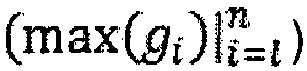
- Unité hydraulique selon la revendication 7, caractérisée en ce que l'unité de commande (31) est conçue de façon à être adaptée pour effectuer un test automatique dans lequel la pompe (26) accumule une pression dont le profil dans le temps est évalué pour détermination des erreurs.
Priority Applications (1)
| Application Number | Priority Date | Filing Date | Title |
|---|---|---|---|
| PL08701388T PL2118501T3 (pl) | 2007-01-12 | 2008-01-10 | Sposób automatycznego określania stanu agregatu hydraulicznego |
Applications Claiming Priority (2)
| Application Number | Priority Date | Filing Date | Title |
|---|---|---|---|
| DE102007001922A DE102007001922A1 (de) | 2007-01-12 | 2007-01-12 | Verfahren zur automatischen Zustandsbestimmung eines Hydraulikaggregates |
| PCT/EP2008/050240 WO2008084077A1 (fr) | 2007-01-12 | 2008-01-10 | Procédé de détermination automatique de l'état d'un groupe hydraulique |
Publications (2)
| Publication Number | Publication Date |
|---|---|
| EP2118501A1 EP2118501A1 (fr) | 2009-11-18 |
| EP2118501B1 true EP2118501B1 (fr) | 2016-01-06 |
Family
ID=39259515
Family Applications (1)
| Application Number | Title | Priority Date | Filing Date |
|---|---|---|---|
| EP08701388.4A Active EP2118501B1 (fr) | 2007-01-12 | 2008-01-10 | Procédé de détermination automatique de l'état d'un groupe hydraulique |
Country Status (6)
| Country | Link |
|---|---|
| US (1) | US8370083B2 (fr) |
| EP (1) | EP2118501B1 (fr) |
| JP (1) | JP2010515588A (fr) |
| DE (1) | DE102007001922A1 (fr) |
| PL (1) | PL2118501T3 (fr) |
| WO (1) | WO2008084077A1 (fr) |
Cited By (1)
| Publication number | Priority date | Publication date | Assignee | Title |
|---|---|---|---|---|
| EP3653888B1 (fr) | 2018-11-13 | 2023-01-25 | Enerpac Tool Group Corp. | Système d'alimentation hydraulique et son procédé de commande |
Families Citing this family (6)
| Publication number | Priority date | Publication date | Assignee | Title |
|---|---|---|---|---|
| US10240593B2 (en) * | 2011-03-04 | 2019-03-26 | Asco Power Technologies, L.P. | Systems and methods of controlling pressure maintenance pumps and data logging pump operations |
| DE102014101714A1 (de) * | 2014-02-12 | 2015-08-13 | Juko Technik Gmbh | Multifunktionales Hydraulikaggregat |
| CN107654361B (zh) * | 2017-10-24 | 2023-05-26 | 吉林大学 | 用于手电泵的一体化检测的设备 |
| US10837472B2 (en) | 2018-02-22 | 2020-11-17 | Caterpillar Inc. | Hydraulic cylinder health monitoring and remaining life system |
| JP7683443B2 (ja) * | 2021-09-28 | 2025-05-27 | 株式会社島津製作所 | 消耗監視装置 |
| USD1042067S1 (en) * | 2023-02-28 | 2024-09-17 | Primesource Consulting Llc | Limited clearance tool |
Family Cites Families (15)
| Publication number | Priority date | Publication date | Assignee | Title |
|---|---|---|---|---|
| US3779457A (en) * | 1971-06-28 | 1973-12-18 | Trw Inc | Data normalizing method and system |
| JPS58193914A (ja) * | 1982-04-09 | 1983-11-11 | Hitachi Constr Mach Co Ltd | 油圧システムの故障予知装置 |
| JPS59194215A (ja) * | 1983-04-18 | 1984-11-05 | Hitachi Constr Mach Co Ltd | 油圧システムの故障予知装置 |
| AT382464B (de) * | 1984-12-21 | 1987-02-25 | Voest Alpine Ag | Verfahren und vorrichtung zur ermittlung eines der leckage einer hydraulikpumpe oder eines hydraulikmotors proportionalen pumpenzustandssignales |
| DE3530137A1 (de) * | 1985-08-23 | 1987-03-05 | Eickhoff Geb | Verfahren und vorrichtung zur anzeige des verschleisszustandes von hydraulikaggregaten |
| GB9515849D0 (en) * | 1995-08-02 | 1995-10-04 | British Gas Plc | Apparatus and method for use in testing gas pressure reduction equipment |
| DE59610857D1 (de) * | 1996-09-28 | 2004-01-22 | Maag Pump Systems Textron Ag Z | Verfahren und Vorrichtung zur Ueberwachung von Systemeinheiten |
| JP2000297443A (ja) * | 1999-04-15 | 2000-10-24 | Komatsu Ltd | 建設機械の情報管理装置 |
| WO2001073224A1 (fr) | 2000-03-31 | 2001-10-04 | Hitachi Construction Machinery Co., Ltd. | Procede de production de mesure d'ecart, systeme et dispositif de sortie |
| US20020077734A1 (en) * | 2000-12-19 | 2002-06-20 | Muller Thomas P. | Hydraulic cylinder life prediction |
| DE20120609U1 (de) * | 2001-12-20 | 2002-03-21 | Beck IPC GmbH, 35578 Wetzlar | Diagnoseeinrichtung für eine fluidtechnische Einrichtung sowie damit ausgestattete fluidtechnische Einrichtung |
| DE10254819A1 (de) * | 2002-11-25 | 2004-06-09 | Robert Bosch Gmbh | Grenzlastabhängiges teilweises Abschalten einzelner Funktionen der Systemkomponenten eines Fahrzeugs |
| NL1025801C2 (nl) * | 2004-03-24 | 2005-09-27 | Demolition And Recycling Equip | Werkwijze en inrichting voor het vaststellen van de bedrijfsomstandigheden waaronder een door een hydraulische zuiger/ cilindercombinatie aangedreven gereedschap wordt bedreven. |
| DE102004017979A1 (de) | 2004-04-14 | 2005-11-03 | Wagner, Paul-Heinz | Verfahren zum winkelgesteuerten Drehen eines Teiles |
| DE102006001585A1 (de) * | 2006-01-12 | 2007-07-19 | Rehau Ag + Co. | Verfahren zur Verschleißüberwachung von Pumpen und Pumpe zur Durchführung des Verfahrens |
-
2007
- 2007-01-12 DE DE102007001922A patent/DE102007001922A1/de not_active Withdrawn
-
2008
- 2008-01-10 JP JP2009545178A patent/JP2010515588A/ja active Pending
- 2008-01-10 PL PL08701388T patent/PL2118501T3/pl unknown
- 2008-01-10 US US12/522,412 patent/US8370083B2/en active Active
- 2008-01-10 WO PCT/EP2008/050240 patent/WO2008084077A1/fr not_active Ceased
- 2008-01-10 EP EP08701388.4A patent/EP2118501B1/fr active Active
Cited By (1)
| Publication number | Priority date | Publication date | Assignee | Title |
|---|---|---|---|---|
| EP3653888B1 (fr) | 2018-11-13 | 2023-01-25 | Enerpac Tool Group Corp. | Système d'alimentation hydraulique et son procédé de commande |
Also Published As
| Publication number | Publication date |
|---|---|
| US20100293933A1 (en) | 2010-11-25 |
| US8370083B2 (en) | 2013-02-05 |
| WO2008084077A1 (fr) | 2008-07-17 |
| EP2118501A1 (fr) | 2009-11-18 |
| JP2010515588A (ja) | 2010-05-13 |
| PL2118501T3 (pl) | 2016-06-30 |
| DE102007001922A1 (de) | 2008-07-17 |
Similar Documents
| Publication | Publication Date | Title |
|---|---|---|
| EP2118501B1 (fr) | Procédé de détermination automatique de l'état d'un groupe hydraulique | |
| DE602004012500T2 (de) | Verfahren zur Diagnose eines zyklischen Systems | |
| EP0653259B1 (fr) | Procédé pour la pose de rivets borgnes et d'écrous aveugles et dispositif pour la pose de rivets borgnes et d'écrous aveugles | |
| EP2258949B1 (fr) | Procédé de détermination de valeurs caractéristiques, notamment de valeurs, notamment de paramètres, d'un agrégat de pompe centrifuge entraîné par moteur électrique intégré dans une installation | |
| EP1607192B1 (fr) | Méthode et système pour estimer l'usure des articulations d'un bras de robot | |
| EP3841366B1 (fr) | Procédé et système pour la détermination directe d'un endommagement théorique d'au moins un organe d'un dispositif | |
| DE3345830A1 (de) | Vorrichtung und verfahren zum ueberwachen des betriebes von pumpeneinheiten | |
| EP3649036B1 (fr) | Procédé pour le fonctionnement d'un système de direction assistée et une direction assistée | |
| DE102019117820A1 (de) | Verfahren und Vorrichtung zur Zustandsüberwachung einer Hydraulikpumpe | |
| DE4316332C2 (de) | Schraubvorrichtung mit Erfassung, Überwachung und Regelung meßbarer Schraubenparameter während des Schraubvorganges und Verfahren zum Herstellen qualitativ hochwertiger Schraubverbindungen | |
| DE102016006343A1 (de) | Mit einer funktion zum erkennen von anomalem bremsen ausgestattete motorsteuerung und verfahren zum erkennen von anomalem bremsen | |
| WO2008071552A1 (fr) | Procédé et dispositif pour diagnostiquer l'état d'une pièce de machine | |
| EP1737619B1 (fr) | Procede de rotation d'un element, regulee en angle | |
| WO2012123284A1 (fr) | Procédé pour faire tourner une partie pivotante | |
| WO2020038666A1 (fr) | Dispositif d'envoi d'un état futur d'un système de lubrification | |
| EP2233249B1 (fr) | Système pour serrer simultanément plusieurs boulonnages en une étape | |
| EP3954831B1 (fr) | Machine de compactage du sol | |
| EP2881584B1 (fr) | Détection de pannes sans capteur pour des pompes de dosage dotées d'un moteur pas à pas | |
| EP4406704A2 (fr) | Procédé de création d'un ensemble de données d'entraînement, procédé d'entraînement d'une intelligence artificielle, intelligence artificielle et machine-outil manuelle | |
| DE69728942T2 (de) | System zur Auswertung des Zustandes einer Vakuumpumpe | |
| EP4026753B1 (fr) | Procédé de détermination de l'usure d'un système de direction d'un véhicule | |
| DE102020204817B4 (de) | Verfahren zur automatisierten Demontage und Montage eines Fahrzeugrads an einem Radflansch und Vorrichtung hierfür | |
| DE102015111316A1 (de) | Hydraulikaggregat zur Schraubprozesssteuerung | |
| EP3120203B1 (fr) | Dispositif et procédé servant à identifier des anomalies dans des machines | |
| DE102017126341A1 (de) | Verfahren und Vorrichtung zur Bestimmung eines Verschleißzustands in einer Hydrostatpumpe |
Legal Events
| Date | Code | Title | Description |
|---|---|---|---|
| PUAI | Public reference made under article 153(3) epc to a published international application that has entered the european phase |
Free format text: ORIGINAL CODE: 0009012 |
|
| 17P | Request for examination filed |
Effective date: 20090707 |
|
| AK | Designated contracting states |
Kind code of ref document: A1 Designated state(s): AT BE BG CH CY CZ DE DK EE ES FI FR GB GR HR HU IE IS IT LI LT LU LV MC MT NL NO PL PT RO SE SI SK TR |
|
| DAX | Request for extension of the european patent (deleted) | ||
| 17Q | First examination report despatched |
Effective date: 20101118 |
|
| GRAP | Despatch of communication of intention to grant a patent |
Free format text: ORIGINAL CODE: EPIDOSNIGR1 |
|
| INTG | Intention to grant announced |
Effective date: 20150707 |
|
| GRAS | Grant fee paid |
Free format text: ORIGINAL CODE: EPIDOSNIGR3 |
|
| GRAA | (expected) grant |
Free format text: ORIGINAL CODE: 0009210 |
|
| AK | Designated contracting states |
Kind code of ref document: B1 Designated state(s): AT BE BG CH CY CZ DE DK EE ES FI FR GB GR HR HU IE IS IT LI LT LU LV MC MT NL NO PL PT RO SE SI SK TR |
|
| REG | Reference to a national code |
Ref country code: GB Ref legal event code: FG4D Free format text: NOT ENGLISH |
|
| REG | Reference to a national code |
Ref country code: CH Ref legal event code: EP |
|
| REG | Reference to a national code |
Ref country code: IE Ref legal event code: FG4D Free format text: LANGUAGE OF EP DOCUMENT: GERMAN |
|
| REG | Reference to a national code |
Ref country code: AT Ref legal event code: REF Ref document number: 769102 Country of ref document: AT Kind code of ref document: T Effective date: 20160215 |
|
| REG | Reference to a national code |
Ref country code: FR Ref legal event code: PLFP Year of fee payment: 9 |
|
| REG | Reference to a national code |
Ref country code: DE Ref legal event code: R096 Ref document number: 502008013716 Country of ref document: DE |
|
| PGFP | Annual fee paid to national office [announced via postgrant information from national office to epo] |
Ref country code: TR Payment date: 20160322 Year of fee payment: 9 |
|
| REG | Reference to a national code |
Ref country code: LT Ref legal event code: MG4D |
|
| REG | Reference to a national code |
Ref country code: NL Ref legal event code: MP Effective date: 20160106 |
|
| PG25 | Lapsed in a contracting state [announced via postgrant information from national office to epo] |
Ref country code: BE Free format text: LAPSE BECAUSE OF NON-PAYMENT OF DUE FEES Effective date: 20160131 |
|
| PG25 | Lapsed in a contracting state [announced via postgrant information from national office to epo] |
Ref country code: NL Free format text: LAPSE BECAUSE OF FAILURE TO SUBMIT A TRANSLATION OF THE DESCRIPTION OR TO PAY THE FEE WITHIN THE PRESCRIBED TIME-LIMIT Effective date: 20160106 |
|
| PG25 | Lapsed in a contracting state [announced via postgrant information from national office to epo] |
Ref country code: GR Free format text: LAPSE BECAUSE OF FAILURE TO SUBMIT A TRANSLATION OF THE DESCRIPTION OR TO PAY THE FEE WITHIN THE PRESCRIBED TIME-LIMIT Effective date: 20160407 Ref country code: FI Free format text: LAPSE BECAUSE OF FAILURE TO SUBMIT A TRANSLATION OF THE DESCRIPTION OR TO PAY THE FEE WITHIN THE PRESCRIBED TIME-LIMIT Effective date: 20160106 Ref country code: NO Free format text: LAPSE BECAUSE OF FAILURE TO SUBMIT A TRANSLATION OF THE DESCRIPTION OR TO PAY THE FEE WITHIN THE PRESCRIBED TIME-LIMIT Effective date: 20160406 Ref country code: HR Free format text: LAPSE BECAUSE OF FAILURE TO SUBMIT A TRANSLATION OF THE DESCRIPTION OR TO PAY THE FEE WITHIN THE PRESCRIBED TIME-LIMIT Effective date: 20160106 Ref country code: ES Free format text: LAPSE BECAUSE OF FAILURE TO SUBMIT A TRANSLATION OF THE DESCRIPTION OR TO PAY THE FEE WITHIN THE PRESCRIBED TIME-LIMIT Effective date: 20160106 |
|
| PG25 | Lapsed in a contracting state [announced via postgrant information from national office to epo] |
Ref country code: PT Free format text: LAPSE BECAUSE OF FAILURE TO SUBMIT A TRANSLATION OF THE DESCRIPTION OR TO PAY THE FEE WITHIN THE PRESCRIBED TIME-LIMIT Effective date: 20160506 Ref country code: IS Free format text: LAPSE BECAUSE OF FAILURE TO SUBMIT A TRANSLATION OF THE DESCRIPTION OR TO PAY THE FEE WITHIN THE PRESCRIBED TIME-LIMIT Effective date: 20160506 Ref country code: LV Free format text: LAPSE BECAUSE OF FAILURE TO SUBMIT A TRANSLATION OF THE DESCRIPTION OR TO PAY THE FEE WITHIN THE PRESCRIBED TIME-LIMIT Effective date: 20160106 Ref country code: LT Free format text: LAPSE BECAUSE OF FAILURE TO SUBMIT A TRANSLATION OF THE DESCRIPTION OR TO PAY THE FEE WITHIN THE PRESCRIBED TIME-LIMIT Effective date: 20160106 Ref country code: SE Free format text: LAPSE BECAUSE OF FAILURE TO SUBMIT A TRANSLATION OF THE DESCRIPTION OR TO PAY THE FEE WITHIN THE PRESCRIBED TIME-LIMIT Effective date: 20160106 |
|
| PGFP | Annual fee paid to national office [announced via postgrant information from national office to epo] |
Ref country code: PL Payment date: 20160229 Year of fee payment: 9 |
|
| REG | Reference to a national code |
Ref country code: CH Ref legal event code: PL |
|
| REG | Reference to a national code |
Ref country code: DE Ref legal event code: R097 Ref document number: 502008013716 Country of ref document: DE |
|
| PG25 | Lapsed in a contracting state [announced via postgrant information from national office to epo] |
Ref country code: EE Free format text: LAPSE BECAUSE OF FAILURE TO SUBMIT A TRANSLATION OF THE DESCRIPTION OR TO PAY THE FEE WITHIN THE PRESCRIBED TIME-LIMIT Effective date: 20160106 Ref country code: DK Free format text: LAPSE BECAUSE OF FAILURE TO SUBMIT A TRANSLATION OF THE DESCRIPTION OR TO PAY THE FEE WITHIN THE PRESCRIBED TIME-LIMIT Effective date: 20160106 Ref country code: CH Free format text: LAPSE BECAUSE OF NON-PAYMENT OF DUE FEES Effective date: 20160131 Ref country code: LI Free format text: LAPSE BECAUSE OF NON-PAYMENT OF DUE FEES Effective date: 20160131 Ref country code: MC Free format text: LAPSE BECAUSE OF FAILURE TO SUBMIT A TRANSLATION OF THE DESCRIPTION OR TO PAY THE FEE WITHIN THE PRESCRIBED TIME-LIMIT Effective date: 20160106 |
|
| REG | Reference to a national code |
Ref country code: IE Ref legal event code: MM4A |
|
| PLBE | No opposition filed within time limit |
Free format text: ORIGINAL CODE: 0009261 |
|
| STAA | Information on the status of an ep patent application or granted ep patent |
Free format text: STATUS: NO OPPOSITION FILED WITHIN TIME LIMIT |
|
| PG25 | Lapsed in a contracting state [announced via postgrant information from national office to epo] |
Ref country code: RO Free format text: LAPSE BECAUSE OF FAILURE TO SUBMIT A TRANSLATION OF THE DESCRIPTION OR TO PAY THE FEE WITHIN THE PRESCRIBED TIME-LIMIT Effective date: 20160106 Ref country code: SK Free format text: LAPSE BECAUSE OF FAILURE TO SUBMIT A TRANSLATION OF THE DESCRIPTION OR TO PAY THE FEE WITHIN THE PRESCRIBED TIME-LIMIT Effective date: 20160106 Ref country code: CZ Free format text: LAPSE BECAUSE OF FAILURE TO SUBMIT A TRANSLATION OF THE DESCRIPTION OR TO PAY THE FEE WITHIN THE PRESCRIBED TIME-LIMIT Effective date: 20160106 |
|
| 26N | No opposition filed |
Effective date: 20161007 |
|
| REG | Reference to a national code |
Ref country code: FR Ref legal event code: PLFP Year of fee payment: 10 |
|
| PG25 | Lapsed in a contracting state [announced via postgrant information from national office to epo] |
Ref country code: IE Free format text: LAPSE BECAUSE OF NON-PAYMENT OF DUE FEES Effective date: 20160110 |
|
| PG25 | Lapsed in a contracting state [announced via postgrant information from national office to epo] |
Ref country code: BG Free format text: LAPSE BECAUSE OF FAILURE TO SUBMIT A TRANSLATION OF THE DESCRIPTION OR TO PAY THE FEE WITHIN THE PRESCRIBED TIME-LIMIT Effective date: 20160406 Ref country code: SI Free format text: LAPSE BECAUSE OF FAILURE TO SUBMIT A TRANSLATION OF THE DESCRIPTION OR TO PAY THE FEE WITHIN THE PRESCRIBED TIME-LIMIT Effective date: 20160106 |
|
| REG | Reference to a national code |
Ref country code: AT Ref legal event code: MM01 Ref document number: 769102 Country of ref document: AT Kind code of ref document: T Effective date: 20160110 |
|
| PG25 | Lapsed in a contracting state [announced via postgrant information from national office to epo] |
Ref country code: AT Free format text: LAPSE BECAUSE OF NON-PAYMENT OF DUE FEES Effective date: 20160110 |
|
| PG25 | Lapsed in a contracting state [announced via postgrant information from national office to epo] |
Ref country code: MT Free format text: LAPSE BECAUSE OF FAILURE TO SUBMIT A TRANSLATION OF THE DESCRIPTION OR TO PAY THE FEE WITHIN THE PRESCRIBED TIME-LIMIT Effective date: 20160106 |
|
| REG | Reference to a national code |
Ref country code: FR Ref legal event code: PLFP Year of fee payment: 11 |
|
| PG25 | Lapsed in a contracting state [announced via postgrant information from national office to epo] |
Ref country code: HU Free format text: LAPSE BECAUSE OF FAILURE TO SUBMIT A TRANSLATION OF THE DESCRIPTION OR TO PAY THE FEE WITHIN THE PRESCRIBED TIME-LIMIT; INVALID AB INITIO Effective date: 20080110 Ref country code: CY Free format text: LAPSE BECAUSE OF FAILURE TO SUBMIT A TRANSLATION OF THE DESCRIPTION OR TO PAY THE FEE WITHIN THE PRESCRIBED TIME-LIMIT Effective date: 20160106 |
|
| PG25 | Lapsed in a contracting state [announced via postgrant information from national office to epo] |
Ref country code: LU Free format text: LAPSE BECAUSE OF NON-PAYMENT OF DUE FEES Effective date: 20160110 |
|
| PG25 | Lapsed in a contracting state [announced via postgrant information from national office to epo] |
Ref country code: PL Free format text: LAPSE BECAUSE OF NON-PAYMENT OF DUE FEES Effective date: 20170110 |
|
| PG25 | Lapsed in a contracting state [announced via postgrant information from national office to epo] |
Ref country code: TR Free format text: LAPSE BECAUSE OF NON-PAYMENT OF DUE FEES Effective date: 20170110 |
|
| PGFP | Annual fee paid to national office [announced via postgrant information from national office to epo] |
Ref country code: GB Payment date: 20260122 Year of fee payment: 19 |
|
| PGFP | Annual fee paid to national office [announced via postgrant information from national office to epo] |
Ref country code: DE Payment date: 20260115 Year of fee payment: 19 |
|
| PGFP | Annual fee paid to national office [announced via postgrant information from national office to epo] |
Ref country code: IT Payment date: 20260130 Year of fee payment: 19 |
|
| PGFP | Annual fee paid to national office [announced via postgrant information from national office to epo] |
Ref country code: FR Payment date: 20260127 Year of fee payment: 19 |