EP2119310B1 - System und verfahren zur bereitstellung von hörhilfe für einen benutzer - Google Patents
System und verfahren zur bereitstellung von hörhilfe für einen benutzer Download PDFInfo
- Publication number
- EP2119310B1 EP2119310B1 EP07711370.2A EP07711370A EP2119310B1 EP 2119310 B1 EP2119310 B1 EP 2119310B1 EP 07711370 A EP07711370 A EP 07711370A EP 2119310 B1 EP2119310 B1 EP 2119310B1
- Authority
- EP
- European Patent Office
- Prior art keywords
- unit
- audio
- link
- right ear
- left ear
- Prior art date
- Legal status (The legal status is an assumption and is not a legal conclusion. Google has not performed a legal analysis and makes no representation as to the accuracy of the status listed.)
- Active
Links
Images

Classifications
-
- H—ELECTRICITY
- H04—ELECTRIC COMMUNICATION TECHNIQUE
- H04R—LOUDSPEAKERS, MICROPHONES, GRAMOPHONE PICK-UPS OR LIKE ACOUSTIC ELECTROMECHANICAL TRANSDUCERS; ELECTRIC HEARING AIDS; PUBLIC ADDRESS SYSTEMS
- H04R25/00—Electric hearing aids
- H04R25/55—Electric hearing aids using an external connection, either wireless or wired
- H04R25/554—Electric hearing aids using an external connection, either wireless or wired using a wireless connection, e.g. between microphone and amplifier or using Tcoils
-
- H—ELECTRICITY
- H04—ELECTRIC COMMUNICATION TECHNIQUE
- H04R—LOUDSPEAKERS, MICROPHONES, GRAMOPHONE PICK-UPS OR LIKE ACOUSTIC ELECTROMECHANICAL TRANSDUCERS; ELECTRIC HEARING AIDS; PUBLIC ADDRESS SYSTEMS
- H04R25/00—Electric hearing aids
- H04R25/40—Arrangements for obtaining a desired directivity characteristic
- H04R25/407—Circuits for combining signals of a plurality of transducers
-
- H—ELECTRICITY
- H04—ELECTRIC COMMUNICATION TECHNIQUE
- H04R—LOUDSPEAKERS, MICROPHONES, GRAMOPHONE PICK-UPS OR LIKE ACOUSTIC ELECTROMECHANICAL TRANSDUCERS; ELECTRIC HEARING AIDS; PUBLIC ADDRESS SYSTEMS
- H04R25/00—Electric hearing aids
- H04R25/55—Electric hearing aids using an external connection, either wireless or wired
- H04R25/552—Binaural
-
- H—ELECTRICITY
- H04—ELECTRIC COMMUNICATION TECHNIQUE
- H04R—LOUDSPEAKERS, MICROPHONES, GRAMOPHONE PICK-UPS OR LIKE ACOUSTIC ELECTROMECHANICAL TRANSDUCERS; ELECTRIC HEARING AIDS; PUBLIC ADDRESS SYSTEMS
- H04R2225/00—Details of deaf aids covered by H04R25/00, not provided for in any of its subgroups
- H04R2225/41—Detection or adaptation of hearing aid parameters or programs to listening situation, e.g. pub, forest
-
- H—ELECTRICITY
- H04—ELECTRIC COMMUNICATION TECHNIQUE
- H04R—LOUDSPEAKERS, MICROPHONES, GRAMOPHONE PICK-UPS OR LIKE ACOUSTIC ELECTROMECHANICAL TRANSDUCERS; ELECTRIC HEARING AIDS; PUBLIC ADDRESS SYSTEMS
- H04R2225/00—Details of deaf aids covered by H04R25/00, not provided for in any of its subgroups
- H04R2225/55—Communication between hearing aids and external devices via a network for data exchange
-
- H—ELECTRICITY
- H04—ELECTRIC COMMUNICATION TECHNIQUE
- H04R—LOUDSPEAKERS, MICROPHONES, GRAMOPHONE PICK-UPS OR LIKE ACOUSTIC ELECTROMECHANICAL TRANSDUCERS; ELECTRIC HEARING AIDS; PUBLIC ADDRESS SYSTEMS
- H04R25/00—Electric hearing aids
- H04R25/55—Electric hearing aids using an external connection, either wireless or wired
- H04R25/558—Remote control, e.g. of amplification, frequency
Definitions
- the present invention relates to a system and a method for providing hearing assistance to a user wherein audio signals from an audio signal source, which usually is a microphone arrangement, are transmitted by a transmission unit via a wireless audio link to a right ear unit and a left ear unit which are worn at or at least in part in the user's right ear and left ear, respectively, and which comprise means for stimulating the respective user's ear according to the transmitted audio signals.
- an audio signal source which usually is a microphone arrangement
- the wireless audio link is an FM (Frequency Modulation) radio link.
- FM Frequency Modulation
- the benefit of such systems is that sound captured by a remote microphone at the transmission unit can be presented at high sound pressure level to the hearing of the user wearing the ear units.
- the level of speech signals from the person using the transmission unit can be increased with regard to acoustic background noise.
- a typical application of wireless audio systems the receiver unit is connected to or integrated into a hearing instrument, such as a hearing aid.
- a hearing instrument such as a hearing aid.
- the benefit of such systems is that the microphone of the hearing instrument can be supplemented or replaced by the remote microphone which produces audio signals which are transmitted wirelessly to the FM receiver and thus to the hearing instrument.
- FM systems have been standard equipment for children with hearing loss in educational settings for many years. Their merit lies in the fact that a microphone placed a few inches from the mouth of a person speaking receives speech at a much higher level than one placed several feet away. This increase in speech level corresponds to an increase in signal-to-noise ratio (SNR) due to the direct wireless connection to the listener's amplification system.
- SNR signal-to-noise ratio
- the resulting improvements of signal level and SNR in the listener's ear are recognized as the primary benefits of FM radio systems, as hearing-impaired individuals are at a significant disadvantage when processing signals with a poor acoustical
- FM+M FM plus hearing instrument combination
- FM+ENV FM plus hearing instrument combination
- This operating mode allows the listener to perceive the speaker's voice from the remote microphone with a good SNR while the integrated hearing instrument microphone allows to listener to also hear environmental sounds. This allows the user/listener to hear and monitor his own voice, as well as voices of other people or environmental noise, as long as the loudness balance between the FM signal and the signal coming from the hearing instrument microphone is properly adjusted.
- An example of an FM system is found in CA 2 422 449 A1 wherein the FM receiver unit is mechanically connected to a hearing instrument.
- Such FM systems often are used in rooms. However, due to reflections in rooms the quality of the reception of the FM audio signals will vary depending upon head movement, position of the user in the room, positions and movement of other people or objects, etc. This varying quality manifests itself by a kind of a hissing noise and is especially noticeable in very small FM receivers as these receivers are built with very small antennas. These "holes" in the FM audio signal reception quality are an issue both with the current analogue FM systems as well as with the upcoming new digital systems.
- binaural hearing systems are already available, wherein there is provided a usually wireless link between the right ear hearing aid and the left ear hearing aid for exchanging data and audio signals between the hearing aids for improving binaural perception of sound.
- Examples of such binaural systems can be found in EP 1 651 005 A2 , US 2004/0037442 A1 and US 6,549,633 B1 .
- EP 1 531 650 A2 a binaural system is described wherein in addition to the binaural link a wireless audio link to a remote microphone is provided.
- a similar system is described in WO 02/074011 A2 .
- EP 1 657 958 A1 relates to a communication system comprising a plurality of hearing aids between which audio signals may be exchanged via wireless links.
- US 2005/0117764 A1 relates to a system comprising a right ear hearing aid and left ear hearing aid, each comprising a hearing coil for receiving audio signals from a telephone.
- the difference between the levels of the input signals of the two hearing devices at the hearing coils is measured and compared with a threshold value. If the difference in levels drops below or exceeds the threshold value, the respective hearing aid is switched to a telephone mode.
- US 2004/0252852 A1 relates to a binaural acoustic beam forming system comprising a right ear hearing aid and a left ear haring aid wherein the voice-to-background noise ratio of the audio signal captured by the microphone of the right ear hearing aid and the audio signal captured by the microphone of the left ear hearing aid is determined and compared and wherein these audio signals are mixed prior to being supplied to the respective loudspeaker of the hearing aids, with the mixing ratio depending on the noise power ratio, i.e. the ratio of the voice to background noise ratios of the left ear hearing aid and the right ear hearing aid, respectively.
- the noise power ratio i.e. the ratio of the voice to background noise ratios of the left ear hearing aid and the right ear hearing aid
- US 2004/0175008 A1 relates to a binaural hearing aid system, wherein at each ear audio signals are captured via two spaced-apart microphones, which audio signals undergo common signal processing in order to achieve binaural effects like beamforming.
- the hearing aids may exchange audio signals via a control unit acting as a weighting unit, which may be controlled by an auditory scene classifier.
- An acoustical signal captured by the microphones of a hearing aid masked by the user's head may be replaced by the acoustical signal as captured by the microphones of the hearing aid worn at the other ear in order to improve SNR, the HRTF should be maintained.
- US 2004/0013280 A1 relates to a binaural hearing aid system, wherein control data is exchanged between the two hearing aids via a wireless link.
- control data is exchanged between an external processor unit and the hearing aids via wireless links
- US 2006/0067550 A1 relates to a plurality of hearing aids which may exchange audio signals captured by the hearing aid microphones via wireless links between the hearing aids.
- the first object is achieved by a system as defined in claim 1 and a method as defined in claim 9, respectively.
- This solution is beneficial in that, by detecting the quality of the right ear link and the left ear link and exchanging audio signals received from the transmission unit between the right ear unit and the left ear unit in order to select, as a function of the detected qualities of the right ear link and the left ear link, as input to the stimulating means the audio signal received by the respective receiver unit directly from the transmission unit, the audio signals received via the audio signal exchange between the right ear unit and the left ear unit and/or mixtures thereof, the quality of the audio signals transmitted from the transmission unit to any of the two ear units can be optimized, since a poor transmission quality of one of the audio links can be compensated by supplying the audio signal transmitted via the audio link having the better quality to both ear units via the audio signal exchange between the ear units. In particular, it is thereby made possible to always select the presently better one of the right ear audio link and the left ear audio link as input to both
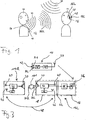
- Figs. 1 and 2 show a hearing assistance system comprising a transmission unit 10 comprising a directional microphone arrangement 12 consisting of two omnidirectional microphones M1 and M2 which are spaced apart, a right ear unit 14R and a left ear unit 14L, each comprising a receiver unit 16 and a hearing instrument 18.
- the hearing instrument 18 comprises a loudspeaker 20.
- the hearing instrument 18 and the receiver unit 16 may be connected by a mechanical/electrical interface 22 (for example, a so-called "audio shoe”), or they may be integrated into a common housing (as indicated by dashed lines in Fig. 2 ).
- the hearing aid 18 could be of any type, for example, BTE (Behind-The-Ear), ITE (In-The-Ear) or CIC (Completely-In-the-Channel).
- the transmission unit 10 may be worn by a speaker 100 around his neck by a neck loop 24 acting as an antenna, with the microphone arrangement 12 capturing the sound waves 105 carrying the speaker's voice.
- the right ear unit 14R is worn at or at least in part in the right ear 26R of the user 101
- the left ear unit 14L is worn at or at least in part in the left ear 26L of the user 101.
- background/surrounding noise 106 may be present.
- the transmission unit 10 comprises an audio signal processing unit 28 for processing the audio signals captured by the microphone arrangement 12 and a transmitter 30 for transmitting the processed audio signals via the antenna 24 via a left ear audio link 32L to the receiver unit 16 of the left ear unit 14L and via a right ear audio link 32R to the receiver unit 16 of the right ear unit 14R.
- Each receiver unit 16 comprises an antenna 34, a receiver 36 and an audio signal processing unit 38 for processing the audio signals received by the receiver 36 via the respective audio link 32R, 32L.
- Each hearing instrument 18 comprises a microphone arrangement 40 (which may comprises a single microphone or two spaced apart microphones) for capturing audio signals at the respective user's ear 26R, 26L, a central unit 42, the loudspeaker 20, a transceiver 44 and a corresponding antenna 46.
- the transceiver 44 and the antenna 46 are provided for establishing a binaural link 48 between the hearing instruments 18 of the right ear unit 14R and the left ear unit 14L, respectively, which serves to exchange audio signals and control data/commands between the right ear unit 14 R and the left ear unit 14L.
- the binaural link 48 serves to exchange audio signals received by the receiver units 16 of the right ear unit 14R and the left ear unit 14L, respectively.
- the central unit 42 serves to process the audio signals received from the built-in microphone arrangement 40, the audio signals supplied by the respective receiver unit 16 and the audio signals received by the transceiver 44 via the binaural link 48 from the hearing instrument 18 of the other one of the right ear unit 14R and the left ear unit 14L, respectively.
- the central unit 42 also serves to control the respective right ear unit 14R and left ear unit 14L.
- the processed audio signals are supplied from the central unit 42 to the speaker 20 for stimulating the respective ear 26R, 26L.
- each of the right ear unit 14R and the left ear unit 14L the quality of the respective right ear audio link 32R and the left ear audio link 32L is monitored. This can be done, for example, by a signal-to-noise- ratio (SNR) measurement of the signals received by the receiver unit 16, by an RSSI (Received Signal Strength Indication) measurement (wherein the energy integral of the signal received by the receiver unit 16 is determined) or, if the links 32R, 32L are digital, by error-rate measurements.
- SNR signal-to-noise- ratio
- RSSI Receiveived Signal Strength Indication
- Such link quality monitoring may be carried-out in the receiver unit 16 (for example, by the audio signal processing unit 38) or in the hearing instrument 18 (for example, by the central unit 42 to which the signal received by the receiver unit 16 is supplied). If the link quality is monitored in the receiver unit 16, the result of the analysis has to be supplied to the hearing instrument 18, see dashed line in Fig. 2 .
- the result of the link quality monitoring is used for improving the quality of the audio signals transmitted by the transmission unit 10 in case that one of the right ear audio link 32R and the left ear audio link 32L has a significantly lower quality than the other one.
- the audio signals received via one of the links 32R, 32L presently having the higher quality are transmitted via the binaural link 48 to the other one of the units 14R, 14L, and there they are used to replace or at least supplement the audio signals received by the receiver unit 16 of that unit 14R, 14L via that one of the links 32R, 32L presently having the lower quality, prior to being supplied as input to the respective loudspeaker 20. Consequently, both the transmission/exchange of audio signals via the binaural link 48 and the selection of the audio signals to be supplied as input to the loudspeaker 20 are controlled according to result of the monitoring of the quality of the audio links 32R, 32L.
- control can be achieved by designing the system architecture such that one of the units 14R, 14L acts as a master and the other one acts as a slave, with the necessary information regarding the quality of the respective audio link 32R, 32L being exchanged/transmitted via the binaural link 48 from the slave to the master and with corresponding control commands being transmitted via the binaural link 48 from the master to the slave.
- the selection of the audio signals which are supplied as input to the loudspeaker 20 is carried out by the central unit 42 of the hearing instrument 18 acting as the master; i.e. the decision is made by the central unit 42 of the master and corresponding control commands, if necessary, are transmitted via the binaural link 48 to the central unit 42 of the hearing instrument 18 of the other one of the units 14R, 14L.
- the binaural link 48 is established once the quality of at least one of the units 32R, 32L has been found to be below a pre-set threshold value, and the audio signals received via the better one of the links 32R, 32L is supplied via the binaural link 48 to that one of the units 14R, 14L having the worse link 32R, 32L where these audio signals are used to replace or at least supplement the audio signals received via the worse one of the links 32R, 32L.
- the audio links 32R. 32L are radio frequency links, such as an analog FM link.
- the links 32R, 32L may be digital audio links.
- the binaural link 48 preferably is a digital link, for example, a FSK (Frequency-Shift-Keying) modulated link.
- FIG. 3 An example, which does not form part of the invention, is shown in Fig. 3 , wherein only one of the ear units (for example, the left ear unit 14L) is provided with a receiver unit 16 for the audio link 32L from the transmission unit 10, whereas the other one of the ear units (in the example of Fig. 3 the right ear unit 114R) does not comprise a receiver unit for the audio signals transmitted from the transmission unit 10, so that the right ear unit 114R comprises only a hearing instrument 18.
- the audio signals received by the left ear unit 14L via the audio link 32L from the transmission unit 10 are permanently supplied via the binaural link 48 to the hearing instrument 18 of the right ear unit 114R in order to supply the audio signals transmitted by the transmission unit 10 via the link 32L and the binaural link 48 to the loudspeaker 20 of the right ear unit 114R.
- binaural hearing instruments 18 capable of establishing a binaural link 48 the need for a second receiver unit 16 for receiving audio signals directly from the transmission unit 10 is eliminated, whereby system complexity is reduced.
- the output of the receiver unit 16 may be connected to a separate high impedance audio input of the hearing instrument 18, as shown in Figs. 2 and 3 , or it may connected to a low impedance audio input of the hearing instrument 18 which is connected in parallel to the microphone 40 (see dashed lines in Figs. 2 and 3 ).
Landscapes
- Engineering & Computer Science (AREA)
- Computer Networks & Wireless Communication (AREA)
- Health & Medical Sciences (AREA)
- General Health & Medical Sciences (AREA)
- Neurosurgery (AREA)
- Otolaryngology (AREA)
- Physics & Mathematics (AREA)
- Acoustics & Sound (AREA)
- Signal Processing (AREA)
- Circuit For Audible Band Transducer (AREA)
- Headphones And Earphones (AREA)
Claims (12)
- System zum Bereitstellen von Hörunterstützung für einen Nutzer (101) mit:einer Audiosignalquelle (12) undeiner Sendeeinheit (10) zum Senden von Audiosignalen von der Audiosignalquelle über eine drahtlose Rechtsohraudioverbindung (32R) an eine Rechtsohreinheit (14R), die am oder mindestens zum Teil im rechten Ohr (26R) des Nutzers zu tragen ist und eine Empfängereinheit (16) und Mittel (20) zum Stimulieren des rechten Ohrs des Nutzers aufweist, und über eine drahtlose Linksohraudioverbindung (32L) zu einer Linksohreinheit (14L), die am oder mindestens zum Teil im linken Ohr (26L) des Nutzers zu tragen ist und eine Empfängereinheit (16) und Mittel (20) zum Stimulieren des linken Ohrs des Nutzers aufweist,gekennzeichnet durchMittel (44, 46) zum Austauschen von von der Sendeeinheit empfangenen Audiosignalen zwischen der Rechtsohreinheit und der Linksohreinheit,Mittel (38, 42) zum Detektieren der Qualität der Rechtsohraudioverbindung und der Qualität der Linksohraudioverbindung undMittel (42) zum Auswählen der mittels der entsprechenden Empfängereinheit von der Sendeeinheit empfangenen Audiosignale, der über die Audiosignalaustauschmittel empfangenen Audiosignale und/oder Mischungen daraus als eine Funktion der erfassten Qualitäten der Rechtsohraudioverbindung und der Linksohraudioverbindung als Eingangssignal für jedes der Stimulationsmittel.
- System gemäß Anspruch 1, wobei die Mittel (44, 46) zum Austauschen von Audiosignalen zwischen der Rechtsohreinheit (14R) und der Linksohreinheit (14L) ein Mittel zum Aufbauen einer drahtlosen binauralen Audioverbindung (48) sind, wobei die Auswahlmittel (42) in die Rechtsohreinheit (14R) und die Linksohreinheit (14L) integriert sind, wobei die Rechtsohreinheit (14R) oder die Linksohreinheit (14L) als Master und die andere Einheit als Slave wirkt, um die jedem der Stimulationsmittel (20) als Eingangssignale zuzuführenden Audiosignale auszuwählen, wobei die Rechtsohreinheit und die Linksohreinheit Mittel (44, 46) zum Aufbauen einer drahtlosen Datenverbindung (48) zum Senden von Information betreffend die Qualität der Audioverbindung (32R, 32L) von der Sendeeinheit (10) zu der Slaveeinheit (14R, 14L) von der Slaveeinheit zu der Mastereinheit (14L, 14R) und zum Senden von Steueranweisungen von der Mastereinheit zu der Slaveeinheit aufzubauen, und wobei die Mittel (44, 46) zum Aufbauen der drahtlosen binauralen Audioverbindung (48) die Mittel zum Aufbauen der drahtlosen Datenverbindung aufweisen.
- System gemäß einem der vorhergehenden Ansprüche, wobei die Rechtsohreinheit (14R) und die Linksohreinheit (14L) jeweils ein Hörgerät sind, in welches die Empfängereinheit (16) integriert ist.
- System gemäß einem der Ansprüche 1 und 2, wobei die Rechtsohrverbindung (14R) und die Linksohrverbindung (14L) jeweils ein Hörgerät (18) aufweisen, welches mit der Empfängereinheit (16) verbunden ist, um mit den von der Empfängereinheit empfangenen Audiosignalen versorgt zu werden.
- System gemäß einem der Ansprüche 3 und 4, wobei die Mittel (44, 46) zum Austauschen von Audiosignalen zwischen der Rechtsohreinheit (14R) und der Linksohreinheit (14L) in den Hörgeräten (18) beinhaltet sind.
- System gemäß einem der Ansprüche 3 bis 5, wobei die Mittel (38) zum Erfassen der Qualität der Rechtsohraudioverbindung (32R) und der Qualität der Linksohraudioverbindung (32L) in die entsprechende Empfängereinheit (16) integriert sind.
- System gemäß einem der Ansprüche 3 bis 5, wobei die Mittel (42) zum Erfassen der Qualität der Rechtsohraudioverbindung (32R) und der Qualität der Linksohraudioverbindung (32L) in das entsprechende Hörgerät (18) integriert sind, und wobei jedes Hörgerät (18) die Stimulationsmittel (20), eine Mikrofonanordnung (40) zum Auffangen von Audiosignalen und eine Audiosignalverarbeitungseinheit (42) zum Verarbeiten der von der Mikrofonanordnung aufgefangenen Audiosignale, der von der Empfängereinheit (16) empfangenen Audiosignale und/oder der von der anderen der Rechtsohreinheit (14R) und der Linksohreinheit (14L) empfangenen Audiosignale aufweist.
- System gemäß einem der vorhergehenden Ansprüche, wobei es sich bei der Audiosignalquelle um eine Mikrofonanordnung (12) handelt, die in die Sendeeinheit (10) integriert ist oder mit dieser verbunden ist.
- Verfahren zur Hörunterstützung eines Nutzers (101), wobei:Audiosignale mittels einer Audiosignalquelle (12) erzeugt werden und mittels einer Sendeeinheit (10) über eine drahtlose Rechtsohraudioverbindung (32R) und einer Rechtsohreinheit (14R), die am oder mindestens zum Teil im rechten Ohr (26R) des Nutzers zu tragen ist und Mittel (20) zum Stimulieren des rechten Ohrs des Nutzers aufweist, und über eine drahtlose Linksrohraudioverbindung (32L) zu einer Linksohreinheit (14L) gesendet werden, die am oder zumindest zum Teil im linken Ohr (26L) des Nutzers zu tragen ist und Mittel (20) zum Stimulieren des linken Ohrs (26L) des Nutzers aufweist,die Qualität der Rechtsohraudioverbindung und die Qualität der Linksohraudioverbindung erfasst wird,von der Sendeeinheit empfangene Audiosignale zwischen der Rechtsohreinheit und der Linksohreinheit gemäß der erfassten Qualität der Rechtsohraudioverbindung und der erfassten Qualität der Linksohraudioverbindung ausgetauscht werden,die von der entsprechenden Empfängereinheit von der Sendeeinheit empfangenen Audiosignale, die von der anderen der Rechtsohreinheit und der Linksohreinheit empfangenen Audiosignale und/oder Mischungen daraus als eine Funktion der erfassten Qualitäten der Rechtsohraudioverbindung und der Linksohraudioverbindung als Eingangssignal für jedes der Stimulationsmittel ausgewählt werden, unddas rechte Ohr des Nutzers und das linke Ohr des Nutzers gemäß den ausgewählten entsprechenden Audiosignalen stimuliert werden.
- Verfahren gemäß Anspruch 9, wobei, falls die Qualität der Rechtsohraudioverbindung (32R) und der Linksohraudioverbindung (32L) als unterhalb eines vorbestimmten Schwellwerts liegend erfasst wird, die Audiosignale, die über diejenige der Rechtsohraudioverbindung und die Linksohraudioverbindung mit der höheren Qualität empfangen wurden, beiden Stimulationsmitteln (20) als Eingangssignal zugeführt werden, wobei die über diejenige der Rechtsohraudioverbindung (32R) und der Linksohraudioverbindung (32L) mit der niedrigeren Qualität empfangenen Audiosignale daran gehindert werden, einem der Stimulationsmittel (20) als Eingangssignal zugeführt zu werden, wobei eine drahtlose binaurale Audioverbindung (48) zwischen der Rechtsohreinheit (14R) und der Linksohreinheit (14L) aufgebaut wird, um von der Sendeeinheit (10) empfangene Audiosignale zwischen der Rechtsohreinheit und der Linksohreinheit auszutauschen, wobei die drahtlose binaurale Audioverbindung (48) digital ist, und wobei die drahtlose binaurale Audioverbindung (48) aufgebaut wird, sobald die Qualität der Rechtsohraudioverbindung (32R) oder der Linksohraudioverbindung (32L) als unterhalb eines vorbestimmten Schwellwerts liegend erfasst wird.
- Verfahren gemäß einem der Ansprüche 9 und 10, wobei die Qualität der Rechtsohraudioverbindung (32R) und die Qualität der Linksohraudioverbindung (32L) bestimmt werden, indem ein Signal-Rausch-Verhältnis, ein Empfangener-Signal-Stärke-Indikations (RSSI)- Wert und/oder eine Fehlerrate gemessen werden.
- Verfahren gemäß einem der Ansprüche 9 bis 11, wobei die Rechtsohreinheit (14R) oder die Linksohreinheit (14L) als ein Master und die andere der beiden Einheiten als ein Slave wirkt, um die jedem der Stimulationsmittel (20) als Eingangssignal zuzuführenden Audiosignale auszuwählen, wobei Information betreffend die Qualität der Audioverbindung zu der Slaveeinheit (14R, 14L) von der Slaveeinheit zu der Mastereinheit (14L, 14R) gesendet wird, wobei Steueranweisungen betreffend die Eingangssignalauswahl für die Stimulationsmittel von der Mastereinheit zu der Slaveeinheit gesendet werden, und wobei die Rechtsohraudioverbindung (32R) und die Linksohraudioverbindung (32L) analoge FM-Verbindungen oder digitale Verbindungen sind.
Applications Claiming Priority (1)
| Application Number | Priority Date | Filing Date | Title |
|---|---|---|---|
| PCT/EP2007/000511 WO2008089784A1 (en) | 2007-01-22 | 2007-01-22 | System and method for providing hearing assistance to a user |
Publications (2)
| Publication Number | Publication Date |
|---|---|
| EP2119310A1 EP2119310A1 (de) | 2009-11-18 |
| EP2119310B1 true EP2119310B1 (de) | 2016-12-14 |
Family
ID=38564521
Family Applications (1)
| Application Number | Title | Priority Date | Filing Date |
|---|---|---|---|
| EP07711370.2A Active EP2119310B1 (de) | 2007-01-22 | 2007-01-22 | System und verfahren zur bereitstellung von hörhilfe für einen benutzer |
Country Status (4)
| Country | Link |
|---|---|
| US (1) | US8526648B2 (de) |
| EP (1) | EP2119310B1 (de) |
| DK (1) | DK2119310T3 (de) |
| WO (1) | WO2008089784A1 (de) |
Cited By (1)
| Publication number | Priority date | Publication date | Assignee | Title |
|---|---|---|---|---|
| US11006226B2 (en) | 2017-03-28 | 2021-05-11 | Widex A/S | Binaural hearing aid system and a method of operating a binaural hearing aid system |
Families Citing this family (36)
| Publication number | Priority date | Publication date | Assignee | Title |
|---|---|---|---|---|
| US8934984B2 (en) | 2007-05-31 | 2015-01-13 | Cochlear Limited | Behind-the-ear (BTE) prosthetic device with antenna |
| US9473859B2 (en) * | 2008-12-31 | 2016-10-18 | Starkey Laboratories, Inc. | Systems and methods of telecommunication for bilateral hearing instruments |
| EP2211579B1 (de) | 2009-01-21 | 2012-07-11 | Oticon A/S | Sendeleistungsregelung in einem stromsparenden drahtlosen Kommunikationssystem |
| KR101209126B1 (ko) * | 2011-06-27 | 2012-12-06 | 경북대학교 산학협력단 | 액티브 지연방법 및 이를 이용한 개선된 무선 양이 보청기 |
| WO2013009672A1 (en) | 2011-07-08 | 2013-01-17 | R2 Wellness, Llc | Audio input device |
| EP2590436B1 (de) * | 2011-11-01 | 2014-05-14 | Phonak AG | Binaurales Hörgerät und Verfahren zum Betreiben des Hörgeräts |
| US9319808B2 (en) * | 2012-11-19 | 2016-04-19 | Gn Resound A/S | Hearing aid having a near field resonant parasitic element |
| US9485592B2 (en) | 2012-12-04 | 2016-11-01 | Sonova Ag | Hearing instrument comprising two antennas |
| DK3031218T3 (en) | 2013-08-09 | 2017-09-11 | Sonova Ag | HEARING DEVICE AND METHOD / HEARING ASSISTANCE SYSTEM AND METHOD |
| EP3713254B1 (de) * | 2013-11-07 | 2024-10-23 | Oticon A/s | Binaurales hörgerätesystem mit zwei drahtlosen schnittstellen |
| KR102112850B1 (ko) * | 2014-01-15 | 2020-05-19 | 삼성전자주식회사 | 전자장치에서 보청기의 배터리 균형을 위한 방법 및 장치 |
| US9557960B2 (en) | 2014-04-08 | 2017-01-31 | Doppler Labs, Inc. | Active acoustic filter with automatic selection of filter parameters based on ambient sound |
| US9736264B2 (en) | 2014-04-08 | 2017-08-15 | Doppler Labs, Inc. | Personal audio system using processing parameters learned from user feedback |
| US9524731B2 (en) * | 2014-04-08 | 2016-12-20 | Doppler Labs, Inc. | Active acoustic filter with location-based filter characteristics |
| US9825598B2 (en) | 2014-04-08 | 2017-11-21 | Doppler Labs, Inc. | Real-time combination of ambient audio and a secondary audio source |
| US9560437B2 (en) | 2014-04-08 | 2017-01-31 | Doppler Labs, Inc. | Time heuristic audio control |
| US10306380B2 (en) | 2014-09-15 | 2019-05-28 | Sonova Ag | Hearing assistance system and method |
| DK3195619T3 (en) | 2014-09-15 | 2018-06-06 | Sonova Ag | HEARING SYSTEM AND ¿METHOD OF HELPING BLUETOOTH PROFILES |
| DE102015201945A1 (de) | 2015-02-04 | 2016-08-04 | Sivantos Pte. Ltd. | Höreinrichtung zur binauralen Versorgung sowie Verfahren zum Betrieb |
| US9860652B2 (en) * | 2015-03-23 | 2018-01-02 | Etymonic Design Incorporated | Test apparatus for binaurally-coupled acoustic devices |
| DK3410744T3 (da) | 2015-07-08 | 2020-11-09 | Oticon As | Fremgangsmåde til valg af transmissionsretning i et binauralt høreapparat |
| US9980189B2 (en) | 2015-10-20 | 2018-05-22 | Bragi GmbH | Diversity bluetooth system and method |
| US9678709B1 (en) | 2015-11-25 | 2017-06-13 | Doppler Labs, Inc. | Processing sound using collective feedforward |
| EP3381203A1 (de) * | 2015-11-24 | 2018-10-03 | Sonova AG | Verfahren zum betrieb eines hörgeräts und betrieb eines hörgeräts gemäss solch eines verfahrens |
| US10853025B2 (en) | 2015-11-25 | 2020-12-01 | Dolby Laboratories Licensing Corporation | Sharing of custom audio processing parameters |
| US11145320B2 (en) | 2015-11-25 | 2021-10-12 | Dolby Laboratories Licensing Corporation | Privacy protection in collective feedforward |
| US9703524B2 (en) | 2015-11-25 | 2017-07-11 | Doppler Labs, Inc. | Privacy protection in collective feedforward |
| US9584899B1 (en) | 2015-11-25 | 2017-02-28 | Doppler Labs, Inc. | Sharing of custom audio processing parameters |
| US10251002B2 (en) * | 2016-03-21 | 2019-04-02 | Starkey Laboratories, Inc. | Noise characterization and attenuation using linear predictive coding |
| EP3799446A1 (de) * | 2016-08-29 | 2021-03-31 | Oticon A/s | Hörgerät mit sprachsteuerungsfunktion |
| US10136229B2 (en) * | 2017-03-24 | 2018-11-20 | Cochlear Limited | Binaural segregation of wireless accessories |
| US10332538B1 (en) * | 2018-08-17 | 2019-06-25 | Apple Inc. | Method and system for speech enhancement using a remote microphone |
| US11134350B2 (en) | 2020-01-10 | 2021-09-28 | Sonova Ag | Dual wireless audio streams transmission allowing for spatial diversity or own voice pickup (OVPU) |
| US11083031B1 (en) | 2020-01-10 | 2021-08-03 | Sonova Ag | Bluetooth audio exchange with transmission diversity |
| WO2022203923A1 (en) * | 2021-03-25 | 2022-09-29 | The General Hospital Corporation | System and method for auditory mirror therapy for hearing disorders |
| EP4109928B1 (de) | 2021-06-21 | 2025-09-03 | Sonova AG | Verfahren und system zum streaming eines mehrkanalaudiosignals zu einem binauralen hörsystem |
Family Cites Families (16)
| Publication number | Priority date | Publication date | Assignee | Title |
|---|---|---|---|---|
| US5721783A (en) | 1995-06-07 | 1998-02-24 | Anderson; James C. | Hearing aid with wireless remote processor |
| US5991419A (en) * | 1997-04-29 | 1999-11-23 | Beltone Electronics Corporation | Bilateral signal processing prosthesis |
| AU733433B2 (en) * | 1998-02-18 | 2001-05-17 | Widex A/S | A binaural digital hearing aid system |
| AU774579B2 (en) * | 1999-10-15 | 2004-07-01 | Phonak Ag | Binaural synchronisation |
| JP4939722B2 (ja) * | 2000-07-14 | 2012-05-30 | ジーエヌ リザウンド エー/エス | 同期式ステレオ聴覚システム |
| US7206421B1 (en) * | 2000-07-14 | 2007-04-17 | Gn Resound North America Corporation | Hearing system beamformer |
| JP2004522333A (ja) | 2000-09-18 | 2004-07-22 | フォーナック アーゲー | 伝送システムの制御方法、同方法の適用、伝送システム、受信装置及び補聴器 |
| DE10048354A1 (de) * | 2000-09-29 | 2002-05-08 | Siemens Audiologische Technik | Verfahren zum Betrieb eines Hörgerätesystems sowie Hörgerätesystem |
| JP2004530310A (ja) | 2001-03-13 | 2004-09-30 | フォーナック アーゲー | 着脱可能な機械的及び/又は電気的結合の形成方法、この方法を使用する聴音装置及び聴音装置システム |
| US20040175008A1 (en) * | 2003-03-07 | 2004-09-09 | Hans-Ueli Roeck | Method for producing control signals, method of controlling signal and a hearing device |
| DE10347212B3 (de) * | 2003-10-10 | 2005-03-24 | Siemens Audiologische Technik Gmbh | Hörhilfevorrichtung zum automatischen Schalten in einen Telefonbetrieb und entsprechendes Verfahren |
| US20050100182A1 (en) * | 2003-11-12 | 2005-05-12 | Gennum Corporation | Hearing instrument having a wireless base unit |
| US8019386B2 (en) * | 2004-03-05 | 2011-09-13 | Etymotic Research, Inc. | Companion microphone system and method |
| DE102004047759B3 (de) * | 2004-09-30 | 2006-06-01 | Siemens Audiologische Technik Gmbh | Verwendung eines Hörhilfegerätesystems mit wenigstens zwei Hörhilfegeräten |
| EP1657958B1 (de) * | 2005-06-27 | 2012-06-13 | Phonak Ag | Kommunikationssystem und Hörgerät |
| EP1651005B1 (de) | 2005-12-19 | 2017-03-22 | Sonova AG | Synchronisierung von erzeugtem Ton bei binauralem Hörsystem |
-
2007
- 2007-01-22 US US12/523,970 patent/US8526648B2/en active Active
- 2007-01-22 WO PCT/EP2007/000511 patent/WO2008089784A1/en not_active Ceased
- 2007-01-22 DK DK07711370.2T patent/DK2119310T3/en active
- 2007-01-22 EP EP07711370.2A patent/EP2119310B1/de active Active
Non-Patent Citations (1)
| Title |
|---|
| None * |
Cited By (1)
| Publication number | Priority date | Publication date | Assignee | Title |
|---|---|---|---|---|
| US11006226B2 (en) | 2017-03-28 | 2021-05-11 | Widex A/S | Binaural hearing aid system and a method of operating a binaural hearing aid system |
Also Published As
| Publication number | Publication date |
|---|---|
| EP2119310A1 (de) | 2009-11-18 |
| US8526648B2 (en) | 2013-09-03 |
| DK2119310T3 (en) | 2017-02-13 |
| US20100128907A1 (en) | 2010-05-27 |
| WO2008089784A1 (en) | 2008-07-31 |
Similar Documents
| Publication | Publication Date | Title |
|---|---|---|
| EP2119310B1 (de) | System und verfahren zur bereitstellung von hörhilfe für einen benutzer | |
| CN106231520B (zh) | 对等联网听力系统 | |
| US8077892B2 (en) | Hearing assistance system including data logging capability and method of operating the same | |
| US8345900B2 (en) | Method and system for providing hearing assistance to a user | |
| US9215535B2 (en) | Hearing assistance system and method | |
| US8270643B2 (en) | System and method for determining directionality of sound detected by as hearing aid | |
| EP1627552B1 (de) | Hörgerätesystem, hörgerät und verfahren zur verarbeitung von audiosignalen | |
| US11700493B2 (en) | Hearing aid comprising a left-right location detector | |
| CN107690117B (zh) | 双耳助听器装置 | |
| US20060067550A1 (en) | Signal transmission between hearing aids | |
| US20100195836A1 (en) | Wireless communication system and method | |
| US20100150387A1 (en) | System and method for providing hearing assistance to a user | |
| CN104640043A (zh) | 包括两个无线接口的双耳助听系统 | |
| US8144903B2 (en) | Wireless communication system | |
| US20100145134A1 (en) | Device for Treatment of Stuttering and Its Use | |
| US20120114158A1 (en) | Hearing assistance system | |
| US20080240477A1 (en) | Wireless multiple input hearing assist device | |
| CN108243381A (zh) | 具有自适应双耳听觉引导的听力设备和相关方法 | |
| EP2078442B1 (de) | Hörhilfesystem mit datenprotokollierungsfähigkeit und betriebsverfahren dafür |
Legal Events
| Date | Code | Title | Description |
|---|---|---|---|
| PUAI | Public reference made under article 153(3) epc to a published international application that has entered the european phase |
Free format text: ORIGINAL CODE: 0009012 |
|
| 17P | Request for examination filed |
Effective date: 20090804 |
|
| AK | Designated contracting states |
Kind code of ref document: A1 Designated state(s): AT BE BG CH CY CZ DE DK EE ES FI FR GB GR HU IE IS IT LI LT LU LV MC NL PL PT RO SE SI SK TR |
|
| DAX | Request for extension of the european patent (deleted) | ||
| 17Q | First examination report despatched |
Effective date: 20150210 |
|
| RAP1 | Party data changed (applicant data changed or rights of an application transferred) |
Owner name: SONOVA AG |
|
| GRAP | Despatch of communication of intention to grant a patent |
Free format text: ORIGINAL CODE: EPIDOSNIGR1 |
|
| INTG | Intention to grant announced |
Effective date: 20160527 |
|
| RIN1 | Information on inventor provided before grant (corrected) |
Inventor name: HAENGGI, STEFAN Inventor name: CALLIAS, FRANCOIS Inventor name: DIJKSTRA, EVERT Inventor name: MARQUIS, FRANCOIS |
|
| GRAJ | Information related to disapproval of communication of intention to grant by the applicant or resumption of examination proceedings by the epo deleted |
Free format text: ORIGINAL CODE: EPIDOSDIGR1 |
|
| GRAR | Information related to intention to grant a patent recorded |
Free format text: ORIGINAL CODE: EPIDOSNIGR71 |
|
| GRAS | Grant fee paid |
Free format text: ORIGINAL CODE: EPIDOSNIGR3 |
|
| INTC | Intention to grant announced (deleted) | ||
| INTG | Intention to grant announced |
Effective date: 20161006 |
|
| GRAA | (expected) grant |
Free format text: ORIGINAL CODE: 0009210 |
|
| AK | Designated contracting states |
Kind code of ref document: B1 Designated state(s): AT BE BG CH CY CZ DE DK EE ES FI FR GB GR HU IE IS IT LI LT LU LV MC NL PL PT RO SE SI SK TR |
|
| REG | Reference to a national code |
Ref country code: GB Ref legal event code: FG4D |
|
| REG | Reference to a national code |
Ref country code: CH Ref legal event code: EP |
|
| REG | Reference to a national code |
Ref country code: IE Ref legal event code: FG4D |
|
| REG | Reference to a national code |
Ref country code: AT Ref legal event code: REF Ref document number: 854528 Country of ref document: AT Kind code of ref document: T Effective date: 20170115 |
|
| REG | Reference to a national code |
Ref country code: DE Ref legal event code: R096 Ref document number: 602007049128 Country of ref document: DE |
|
| REG | Reference to a national code |
Ref country code: DK Ref legal event code: T3 Effective date: 20170209 |
|
| PG25 | Lapsed in a contracting state [announced via postgrant information from national office to epo] |
Ref country code: LV Free format text: LAPSE BECAUSE OF FAILURE TO SUBMIT A TRANSLATION OF THE DESCRIPTION OR TO PAY THE FEE WITHIN THE PRESCRIBED TIME-LIMIT Effective date: 20161214 |
|
| REG | Reference to a national code |
Ref country code: LT Ref legal event code: MG4D |
|
| REG | Reference to a national code |
Ref country code: NL Ref legal event code: MP Effective date: 20161214 |
|
| PG25 | Lapsed in a contracting state [announced via postgrant information from national office to epo] |
Ref country code: GR Free format text: LAPSE BECAUSE OF FAILURE TO SUBMIT A TRANSLATION OF THE DESCRIPTION OR TO PAY THE FEE WITHIN THE PRESCRIBED TIME-LIMIT Effective date: 20170315 Ref country code: LT Free format text: LAPSE BECAUSE OF FAILURE TO SUBMIT A TRANSLATION OF THE DESCRIPTION OR TO PAY THE FEE WITHIN THE PRESCRIBED TIME-LIMIT Effective date: 20161214 Ref country code: SE Free format text: LAPSE BECAUSE OF FAILURE TO SUBMIT A TRANSLATION OF THE DESCRIPTION OR TO PAY THE FEE WITHIN THE PRESCRIBED TIME-LIMIT Effective date: 20161214 |
|
| REG | Reference to a national code |
Ref country code: AT Ref legal event code: MK05 Ref document number: 854528 Country of ref document: AT Kind code of ref document: T Effective date: 20161214 |
|
| PG25 | Lapsed in a contracting state [announced via postgrant information from national office to epo] |
Ref country code: BE Free format text: LAPSE BECAUSE OF NON-PAYMENT OF DUE FEES Effective date: 20170131 Ref country code: FI Free format text: LAPSE BECAUSE OF FAILURE TO SUBMIT A TRANSLATION OF THE DESCRIPTION OR TO PAY THE FEE WITHIN THE PRESCRIBED TIME-LIMIT Effective date: 20161214 |
|
| PG25 | Lapsed in a contracting state [announced via postgrant information from national office to epo] |
Ref country code: NL Free format text: LAPSE BECAUSE OF FAILURE TO SUBMIT A TRANSLATION OF THE DESCRIPTION OR TO PAY THE FEE WITHIN THE PRESCRIBED TIME-LIMIT Effective date: 20161214 |
|
| PG25 | Lapsed in a contracting state [announced via postgrant information from national office to epo] |
Ref country code: IS Free format text: LAPSE BECAUSE OF FAILURE TO SUBMIT A TRANSLATION OF THE DESCRIPTION OR TO PAY THE FEE WITHIN THE PRESCRIBED TIME-LIMIT Effective date: 20170414 Ref country code: CZ Free format text: LAPSE BECAUSE OF FAILURE TO SUBMIT A TRANSLATION OF THE DESCRIPTION OR TO PAY THE FEE WITHIN THE PRESCRIBED TIME-LIMIT Effective date: 20161214 Ref country code: EE Free format text: LAPSE BECAUSE OF FAILURE TO SUBMIT A TRANSLATION OF THE DESCRIPTION OR TO PAY THE FEE WITHIN THE PRESCRIBED TIME-LIMIT Effective date: 20161214 Ref country code: RO Free format text: LAPSE BECAUSE OF FAILURE TO SUBMIT A TRANSLATION OF THE DESCRIPTION OR TO PAY THE FEE WITHIN THE PRESCRIBED TIME-LIMIT Effective date: 20161214 Ref country code: SK Free format text: LAPSE BECAUSE OF FAILURE TO SUBMIT A TRANSLATION OF THE DESCRIPTION OR TO PAY THE FEE WITHIN THE PRESCRIBED TIME-LIMIT Effective date: 20161214 |
|
| PG25 | Lapsed in a contracting state [announced via postgrant information from national office to epo] |
Ref country code: ES Free format text: LAPSE BECAUSE OF FAILURE TO SUBMIT A TRANSLATION OF THE DESCRIPTION OR TO PAY THE FEE WITHIN THE PRESCRIBED TIME-LIMIT Effective date: 20161214 Ref country code: BE Free format text: LAPSE BECAUSE OF FAILURE TO SUBMIT A TRANSLATION OF THE DESCRIPTION OR TO PAY THE FEE WITHIN THE PRESCRIBED TIME-LIMIT Effective date: 20161214 Ref country code: AT Free format text: LAPSE BECAUSE OF FAILURE TO SUBMIT A TRANSLATION OF THE DESCRIPTION OR TO PAY THE FEE WITHIN THE PRESCRIBED TIME-LIMIT Effective date: 20161214 Ref country code: PT Free format text: LAPSE BECAUSE OF FAILURE TO SUBMIT A TRANSLATION OF THE DESCRIPTION OR TO PAY THE FEE WITHIN THE PRESCRIBED TIME-LIMIT Effective date: 20170414 Ref country code: PL Free format text: LAPSE BECAUSE OF FAILURE TO SUBMIT A TRANSLATION OF THE DESCRIPTION OR TO PAY THE FEE WITHIN THE PRESCRIBED TIME-LIMIT Effective date: 20161214 Ref country code: IT Free format text: LAPSE BECAUSE OF FAILURE TO SUBMIT A TRANSLATION OF THE DESCRIPTION OR TO PAY THE FEE WITHIN THE PRESCRIBED TIME-LIMIT Effective date: 20161214 Ref country code: BG Free format text: LAPSE BECAUSE OF FAILURE TO SUBMIT A TRANSLATION OF THE DESCRIPTION OR TO PAY THE FEE WITHIN THE PRESCRIBED TIME-LIMIT Effective date: 20170314 |
|
| REG | Reference to a national code |
Ref country code: CH Ref legal event code: PL |
|
| REG | Reference to a national code |
Ref country code: DE Ref legal event code: R097 Ref document number: 602007049128 Country of ref document: DE |
|
| PG25 | Lapsed in a contracting state [announced via postgrant information from national office to epo] |
Ref country code: MC Free format text: LAPSE BECAUSE OF FAILURE TO SUBMIT A TRANSLATION OF THE DESCRIPTION OR TO PAY THE FEE WITHIN THE PRESCRIBED TIME-LIMIT Effective date: 20161214 |
|
| PLBE | No opposition filed within time limit |
Free format text: ORIGINAL CODE: 0009261 |
|
| STAA | Information on the status of an ep patent application or granted ep patent |
Free format text: STATUS: NO OPPOSITION FILED WITHIN TIME LIMIT |
|
| REG | Reference to a national code |
Ref country code: FR Ref legal event code: ST Effective date: 20170929 |
|
| PG25 | Lapsed in a contracting state [announced via postgrant information from national office to epo] |
Ref country code: CH Free format text: LAPSE BECAUSE OF NON-PAYMENT OF DUE FEES Effective date: 20170131 Ref country code: LI Free format text: LAPSE BECAUSE OF NON-PAYMENT OF DUE FEES Effective date: 20170131 Ref country code: FR Free format text: LAPSE BECAUSE OF NON-PAYMENT OF DUE FEES Effective date: 20170214 |
|
| REG | Reference to a national code |
Ref country code: IE Ref legal event code: MM4A |
|
| 26N | No opposition filed |
Effective date: 20170915 |
|
| PG25 | Lapsed in a contracting state [announced via postgrant information from national office to epo] |
Ref country code: LU Free format text: LAPSE BECAUSE OF NON-PAYMENT OF DUE FEES Effective date: 20170122 |
|
| PG25 | Lapsed in a contracting state [announced via postgrant information from national office to epo] |
Ref country code: IE Free format text: LAPSE BECAUSE OF NON-PAYMENT OF DUE FEES Effective date: 20170122 Ref country code: SI Free format text: LAPSE BECAUSE OF FAILURE TO SUBMIT A TRANSLATION OF THE DESCRIPTION OR TO PAY THE FEE WITHIN THE PRESCRIBED TIME-LIMIT Effective date: 20161214 |
|
| PG25 | Lapsed in a contracting state [announced via postgrant information from national office to epo] |
Ref country code: HU Free format text: LAPSE BECAUSE OF FAILURE TO SUBMIT A TRANSLATION OF THE DESCRIPTION OR TO PAY THE FEE WITHIN THE PRESCRIBED TIME-LIMIT; INVALID AB INITIO Effective date: 20070122 |
|
| PG25 | Lapsed in a contracting state [announced via postgrant information from national office to epo] |
Ref country code: CY Free format text: LAPSE BECAUSE OF NON-PAYMENT OF DUE FEES Effective date: 20161214 |
|
| PG25 | Lapsed in a contracting state [announced via postgrant information from national office to epo] |
Ref country code: TR Free format text: LAPSE BECAUSE OF FAILURE TO SUBMIT A TRANSLATION OF THE DESCRIPTION OR TO PAY THE FEE WITHIN THE PRESCRIBED TIME-LIMIT Effective date: 20161214 |
|
| P01 | Opt-out of the competence of the unified patent court (upc) registered |
Effective date: 20230530 |
|
| PGFP | Annual fee paid to national office [announced via postgrant information from national office to epo] |
Ref country code: DK Payment date: 20250127 Year of fee payment: 19 |
|
| PGFP | Annual fee paid to national office [announced via postgrant information from national office to epo] |
Ref country code: GB Payment date: 20250127 Year of fee payment: 19 |
|
| PGFP | Annual fee paid to national office [announced via postgrant information from national office to epo] |
Ref country code: DE Payment date: 20260128 Year of fee payment: 20 |