EP2119462A1 - Kanülenanordnung - Google Patents
Kanülenanordnung Download PDFInfo
- Publication number
- EP2119462A1 EP2119462A1 EP09160356A EP09160356A EP2119462A1 EP 2119462 A1 EP2119462 A1 EP 2119462A1 EP 09160356 A EP09160356 A EP 09160356A EP 09160356 A EP09160356 A EP 09160356A EP 2119462 A1 EP2119462 A1 EP 2119462A1
- Authority
- EP
- European Patent Office
- Prior art keywords
- cannula
- channel
- arrangement according
- handle
- protective device
- Prior art date
- Legal status (The legal status is an assumption and is not a legal conclusion. Google has not performed a legal analysis and makes no representation as to the accuracy of the status listed.)
- Granted
Links
Images




Classifications
-
- A—HUMAN NECESSITIES
- A61—MEDICAL OR VETERINARY SCIENCE; HYGIENE
- A61M—DEVICES FOR INTRODUCING MEDIA INTO, OR ONTO, THE BODY; DEVICES FOR TRANSDUCING BODY MEDIA OR FOR TAKING MEDIA FROM THE BODY; DEVICES FOR PRODUCING OR ENDING SLEEP OR STUPOR
- A61M5/00—Devices for bringing media into the body in a subcutaneous, intra-vascular or intramuscular way; Accessories therefor, e.g. filling or cleaning devices, arm-rests
- A61M5/14—Infusion devices, e.g. infusing by gravity; Blood infusion; Accessories therefor
- A61M5/158—Needles for infusions; Accessories therefor, e.g. for inserting infusion needles, or for holding them on the body
-
- A—HUMAN NECESSITIES
- A61—MEDICAL OR VETERINARY SCIENCE; HYGIENE
- A61M—DEVICES FOR INTRODUCING MEDIA INTO, OR ONTO, THE BODY; DEVICES FOR TRANSDUCING BODY MEDIA OR FOR TAKING MEDIA FROM THE BODY; DEVICES FOR PRODUCING OR ENDING SLEEP OR STUPOR
- A61M25/00—Catheters; Hollow probes
- A61M25/01—Introducing, guiding, advancing, emplacing or holding catheters
- A61M25/06—Body-piercing guide needles or the like
- A61M25/0612—Devices for protecting the needle; Devices to help insertion of the needle, e.g. wings or holders
- A61M25/0631—Devices for protecting the needle; Devices to help insertion of the needle, e.g. wings or holders having means for fully covering the needle after its withdrawal, e.g. needle being withdrawn inside the handle or a cover being advanced over the needle
-
- A—HUMAN NECESSITIES
- A61—MEDICAL OR VETERINARY SCIENCE; HYGIENE
- A61M—DEVICES FOR INTRODUCING MEDIA INTO, OR ONTO, THE BODY; DEVICES FOR TRANSDUCING BODY MEDIA OR FOR TAKING MEDIA FROM THE BODY; DEVICES FOR PRODUCING OR ENDING SLEEP OR STUPOR
- A61M25/00—Catheters; Hollow probes
- A61M25/01—Introducing, guiding, advancing, emplacing or holding catheters
- A61M25/06—Body-piercing guide needles or the like
- A61M25/0612—Devices for protecting the needle; Devices to help insertion of the needle, e.g. wings or holders
- A61M25/0637—Butterfly or winged devices, e.g. for facilitating handling or for attachment to the skin
-
- A—HUMAN NECESSITIES
- A61—MEDICAL OR VETERINARY SCIENCE; HYGIENE
- A61M—DEVICES FOR INTRODUCING MEDIA INTO, OR ONTO, THE BODY; DEVICES FOR TRANSDUCING BODY MEDIA OR FOR TAKING MEDIA FROM THE BODY; DEVICES FOR PRODUCING OR ENDING SLEEP OR STUPOR
- A61M5/00—Devices for bringing media into the body in a subcutaneous, intra-vascular or intramuscular way; Accessories therefor, e.g. filling or cleaning devices, arm-rests
- A61M5/14—Infusion devices, e.g. infusing by gravity; Blood infusion; Accessories therefor
- A61M5/158—Needles for infusions; Accessories therefor, e.g. for inserting infusion needles, or for holding them on the body
- A61M2005/1581—Right-angle needle-type devices
-
- A—HUMAN NECESSITIES
- A61—MEDICAL OR VETERINARY SCIENCE; HYGIENE
- A61M—DEVICES FOR INTRODUCING MEDIA INTO, OR ONTO, THE BODY; DEVICES FOR TRANSDUCING BODY MEDIA OR FOR TAKING MEDIA FROM THE BODY; DEVICES FOR PRODUCING OR ENDING SLEEP OR STUPOR
- A61M2205/00—General characteristics of the apparatus
- A61M2205/58—Means for facilitating use, e.g. by people with impaired vision
- A61M2205/583—Means for facilitating use, e.g. by people with impaired vision by visual feedback
-
- A—HUMAN NECESSITIES
- A61—MEDICAL OR VETERINARY SCIENCE; HYGIENE
- A61M—DEVICES FOR INTRODUCING MEDIA INTO, OR ONTO, THE BODY; DEVICES FOR TRANSDUCING BODY MEDIA OR FOR TAKING MEDIA FROM THE BODY; DEVICES FOR PRODUCING OR ENDING SLEEP OR STUPOR
- A61M5/00—Devices for bringing media into the body in a subcutaneous, intra-vascular or intramuscular way; Accessories therefor, e.g. filling or cleaning devices, arm-rests
- A61M5/178—Syringes
- A61M5/31—Details
- A61M5/32—Needles; Details of needles pertaining to their connection with syringe or hub; Accessories for bringing the needle into, or holding the needle on, the body; Devices for protection of needles
- A61M5/3205—Apparatus for removing or disposing of used needles or syringes, e.g. containers; Means for protection against accidental injuries from used needles
- A61M5/321—Means for protection against accidental injuries by used needles
- A61M5/3216—Caps placed transversally onto the needle, e.g. pivotally attached to the needle base
Definitions
- the invention relates to a cannula assembly comprising a cannula having a proximal portion and a distal portion, which enclose a right or a substantially right angle to each other, a handle extending from the proximal portion comprising a central portion receiving the proximal portion and extending therefrom preferably to this pivotable wings and after use of the cannula the distal portion covering protective device which is pivotally articulated to the handle and about a perpendicular to the proximal cannula portion and parallel to a plane spanned by the wings extending in a plane plane extending axis and a channel-shaped Having portion for receiving the distal portion of the cannula and is fixed in the channel-shaped portion when it is taken from the channel-shaped portion distal cannula portion.
- Corresponding angled cannulas with a wing-like handle are known as port cannulas which are intended to supply a port implanted in a body with medicaments.
- the port has a membrane with a thickness z. B. between 3 mm and 5 mm and a diameter of example 10 mm to 20 mm, which must be punctured by the distal portion of the cannula to then deliver the drug.
- the proximal section is fixed on the skin of the patient by means of the wings.
- the proximal portion is connected to a detachable hose, the end z. B. may have a luer adapter with screw cap to allow connection to a medication container.
- the distal section is covered by a protective device, which after the cannula US-B-6,500,155 is formed by the wings of the handle itself.
- the wings in relation to the distal, ie angled portion of the cannula, a positioning and an extension that the distal portion between the wings is fixed, which in turn are interconnected by latching means such as latching projection and latching recess.
- latching means such as latching projection and latching recess.
- each blade itself In order to use dimensionally equal blades for different cannulae lengths, which may be up to 40mm long, each blade itself must have a length of about 45mm. This dimensioning leads to a relatively large bearing surface of the wings on the skin when the drug is supplied to the port. As a result, relatively large rice zones are created, which are unpleasant.
- JP-A-2007195827 is to remove a port cannula, in which a flexible tube can be pushed over the distal portion to its cover.
- the tube is positioned in a tubular portion of a handle extending along the proximal portion.
- a port cannula after the DE-T-699 35 347 also has a wing assembly as a handle, which is displaceable along the proximal portion of the cannula so as to be able to surround with an outer portion of the tip of the distal portion of the cannula.
- the US-A-2006/0030825 provides a protective device for a distal portion of a port cannula, which is formed as a separate part and after use of the cannula surrounding this detent.
- a cannula assembly of the type mentioned is the US-A-6,921,388 to refer to a port cannula with a protective cap which is pivotable to allow protection after use.
- the cap on a distal portion of the cannula receiving in the section U-shaped portion, emanating from the inner wall locking projections, which are engaged behind with covered cannula of this.
- the WO-A-2002/45574 refers to a port cannula with protective cap.
- the protective cap is slidable in the longitudinal direction of the cannula to cover the cannula tip when not in use.
- the protective cap has a plate-shaped enlargement, which facilitates an adjustment of the protective cap for covering the cannula.
- the plate-shaped extension is hinged to the protective cap.
- the present invention is based on the object, a cannula assembly of the type mentioned in such a way that with a structurally simple design and secure coverage of the distal portion of the cannula after use in the use of the cannula obstruction by the cover is omitted. Also, according to a further aspect of the invention, a simplification of the handling of the cannula even when piercing the port to be made possible, so the distal portion can be accurately aligned on the port.
- the invention essentially provides that the protective device is fixed in the use position of the cannula in a position extending along the middle section of the handle.
- the protective device can be pivoted and fixed in such a way that obstruction in the use of the port cannula is ruled out.
- the protective cap extends along the handle, so that the protective cap does not bother.
- the bottom wall of the protective device is fixed on the central portion of the handle.
- the invention proposes that the bottom wall of the channel-shaped portion of the protective device has a first latching means, which is associated with a present in the central portion of the handle second latching means for latching the channel-shaped portion.
- the bottom wall extend parallel to the axis at least in a longitudinal region and have the latching means.
- the protective device is connected to the handle via a hinge, by means of which the protective device in the use position in a dead center position and along the handle is running fixed.
- the channel-shaped portion is pivotable about a perpendicular to the proximal cannula portion and parallel to a plane spanned by the unverschwenkten wings axis and that the bottom wall of the channel-shaped portion at least in a longitudinal region parallel to the Axis extends and has a first latching means, which is associated with a present in the central portion of the handle second latching means for latching the channel-shaped portion to the central portion.
- the first locking means is a recess and the second locking means is a projection or vice versa.
- the pivot axis itself can be formed by a film hinge.
- the film hinge extends between the central portion of the handle and a proximal planar extension of the protective device, which merges into the bottom wall of the channel-shaped portion.
- the planar enlargement has a greater extent than the bottom wall transversely to the longitudinal axis of the proximal cannula section.
- the bottom wall and the flat extension run along the middle section of the handle and are fixed on the latter, wherein the longitudinal axis of the distal cannula section passes through the planar enlargement.
- the longitudinal axis passes through the planar enlargement in the middle or approximately in the center.
- the protective device is connected to the handle via a hinge, by means of which the protective device can be fixed to run in a dead center position along the handle.
- Other technical possibilities for fixing the handle in the use position are also possible.
- planar extension ensures that the angled portion of the cannula, so the distal portion can be precisely aligned on the port, and then inserted into this.
- the protective device according to the invention is hinged to the handle.
- the wings of the handle can be optimally dimensioned to avoid irritation of the skin with set cannula, since a geometric adaptation to the longitudinal extent of the distal cannula portion to be covered is not required.
- the protective device which, when the distal cannula portion is in this, can not be pivoted uncontrollably, otherwise the cannula would be exposed again.
- the channel-shaped portion viewed perpendicular to the longitudinal axis, the geometry of a U, wherein the channel-shaped portion should be closed at the end.
- the channel-shaped portion may have an open circle-like geometry, in particular such a circular section. Regardless of the geometry, it is provided that the inner projection is more movable toward the bottom surface than toward the opening side of the channel-shaped portion, thereby facilitating insertion into the space between the projection and the bottom surface and preventing pivotal movement.
- the at least one inner projection extends from a first side inner surface of the channel-shaped portion and is at least section opening side in the direction of Bottom surface of the channel-shaped portion inclined.
- a problem-free introduction of the cannula portion is possible in the protective device, since the cannula portion is guided over the projection in the region between this and the bottom wall of the channel-shaped portion.
- the inner projection along the bottom surface and transversely to the longitudinal axis of the channel-shaped portion should have a clearance, which is smaller than the diameter of the distal cannula portion, as viewed to the opposite second side surface and / or to a second inner projection extending therefrom.
- the invention provides that two pairs of inner projections are provided, wherein one of the projections of each pair emanate from the first side inner surface and the other projection from the second side inner surface.
- the projections have approximately a tooth-like structure with the outside surface inclined toward the bottom surface.
- the inner projection should be more movable in the direction of the bottom surface than in the opening side of the channel-shaped portion, so that when covering the distal cannula portion during pivoting of the cannula in the direction of the bottom surface, a small resistance by the projections, but a large then prevails on the protective device, d. H. the channel-shaped portion acts in this fixed cannula portion a force that could allow pivoting back.
- a cannula assembly 10 which includes a port cannula 12 with handle 14 and protective device 16.
- the port cannula 12 includes a proximal portion 18 and a distal portion 20 perpendicular thereto, having distally a ground point 22 pierceable into a port implanted in a body to deliver medication.
- a tube 24 can be pushed, which in turn is shut off or releasable by a hose clamp 26.
- a Luer adapter 28 with screw cap is located at the end of the tube 24 at the end of the proximal portion 18 of the cannula 12 in the usual way.
- the handle 14 has a proximal portion 18 of the cannula 12 surrounding central portion 30, which is cuboid in the embodiment. From the side surfaces 32, 34 of the central portion 30 go out wings 36, 38, which are preferably 29schenkbar to the central portion 30, without this being a mandatory feature. On the underside, the wings 36, 38 are structured so as to avoid a flat support when fixing the cannula 12 to a patient's skin.
- the protective device 16 is formed integrally with the handle 14 as sprayed, wherein between the central portion 30 and the protective device 16 for pivoting a film hinge 40 extends perpendicular to the cannula 12, so both to the proximal portion 38 and to the distal portion 20 extends. Further, the film hinge 40 is parallel to a plane which is spanned by the wings 36, 38 in the non-pivoted state, as can be seen from the figures.
- the film hinge 40 defines the pivot axis, which is therefore also designated by the reference numeral 40, about which a channel-shaped portion 42 of the protective device 16 to the handle 14 and away from this is pivotable, as will be explained below.
- the channel-shaped portion 42 is formed in the embodiment in the U-shaped section and closed at the end (end wall 44). Consequently, the channel-shaped portion 42 has side walls 46, 48 and a bottom wall 50.
- the channel-shaped portion 42, d. H. its bottom wall 50 merges into a flat extension 52, which is connected via the film hinge 40 with the central portion 30 of the handle 14.
- the planar enlargement 52 is structured on its underside 54 in order to prevent the cannula 12, ie, the cannula 12, from being set.
- H. Insertion of the distal portion 20 of the cannula serve as a positioning aid.
- the user when placed, with the wings 36, 38 on top of each other to allow handling, the user has a relatively large area available to guide the distal portion 20 to allow secure piercing of the tip 22 into the port becomes.
- the projections 56, 58, 60, 62 should extend approximately parallel to the bottom surface, so that the projections, 56, 58, 60, 62 wall side have a greater thickness than the end.
- the projections 56, 58, 60, 62 should be dimensioned and arranged so that upon application of a force in the direction of the bottom surface 64 is given a greater mobility than in the opposite direction acting force.
- a recess 74 which is assigned a projection 76 projecting perpendicularly from the middle section 30 of the handle 14.
- the protective device 16 in the manufacturing state, in which the protective device 16, together with the handle 14, the cannula 12, ie, the proximal portion 18 and partially the distal portion 20 are molded.
- the longitudinal axis of the protection device 16 extends along the plane spanned by the wings 36, 38 plane.
- the protective device 16 is pivoted about the pivot axis predetermining film hinge 40 in the direction of the handle 14, so that the projection 76, which protrudes from the outside of the central or central portion 30 of the handle 14, can engage, so that an obstruction by the protective device 16 when using the cannula assembly 10 can not be done.
- the protective device 16 can be connected to the handle 14 via a hinge with so-called dead center. This means that when the protective device 16 is pivoted to the wings 36, 38, the hinge occupies a dead center position and thus the protective device 16 can not be pivoted uncontrollably.
- the state of use of the cannula assembly 10 results from the Fig. 6 to 8 , It can be seen that the channel-shaped portion 42 of the protector 16 to be designated as a protective cap lies with the outer side 78 of the bottom wall 50 on the upper outer surface 80 of the central portion 30 of the handle 14, the projection 76 engaging in the recess 74.
- the planar extension 52 of the protective device 16 extends along the surface 80, as the Fig. 6 and 7 clarify. It is the structured surface 54 of the extension 52 outboard. Further, the film hinge 40 and the planar extension 52 are arranged or formed such that the latter is penetrated by the distal portion 20 of the cannula 12. Optionally, a central enforcement can take place.
- the wings 36, 38 are folded so as to lie in regions, in order to align the cannula assembly 10 to a region of a patient in which a piercing into a port can take place.
- the planar extension 52 serves as a maneuvering aid, so that positionally accurate alignment of the distal portion 22 on the port, d. H. can be done for piercing the membrane.
- the wings 36, 38 are unfolded backwards and fixed on the skin of the patient by means of a plaster. Since the dimensioning, d. H. planar extension of the wings 36, 38 must be adjusted only to the safe handling of the cannula assembly 10 and not to the length of the distal portion 20, a relatively small areal extent can be selected, whereby irritation of the skin is reduced.
- the cannula 12 is removed and then the guard 16 is pivoted counterclockwise around the living hinge 40 in the drawings until the distal portion 20 passes through the opening of the channel-shaped portion 42 and the protrusions 56, 58, 60, 62 overcomes to get into the space between them and the bottom surface 64 of the channel-shaped portion 42.
- the distal portion 20 is fixed, since even if on the channel-shaped portion 42, a force for pivoting about the film hinge 40, so should take place in the drawings in the clockwise direction, the projections 56, 58, 60, 62 due to Dimensioning and design can not be overcome, so that a secure cover of the used distal cannula portion 20 is ensured.
Landscapes
- Health & Medical Sciences (AREA)
- Life Sciences & Earth Sciences (AREA)
- Animal Behavior & Ethology (AREA)
- Engineering & Computer Science (AREA)
- Anesthesiology (AREA)
- Biomedical Technology (AREA)
- Heart & Thoracic Surgery (AREA)
- Hematology (AREA)
- General Health & Medical Sciences (AREA)
- Public Health (AREA)
- Veterinary Medicine (AREA)
- Pulmonology (AREA)
- Biophysics (AREA)
- Vascular Medicine (AREA)
- Infusion, Injection, And Reservoir Apparatuses (AREA)
Abstract
Description
- Die Erfindung bezieht sich auf eine Kanülenanordnung umfassend eine Kanüle mit einem proximalen Abschnitt und einem distalen Abschnitt, die zueinander einen rechten oder einen im Wesentlichen rechten Winkel einschließen, eine von dem proximalen Abschnitt ausgehende Handhabe umfassend einen den proximalen Abschnitt aufnehmenden Mittelabschnitt mit von diesem ausgehenden und vorzugsweise zu diesem verschwenkbaren Flügeln sowie eine nach Gebrauch der Kanüle den distalen Abschnitt abdeckende Schutzeinrichtung, die verschwenkbar an der Handhabe angelenkt und um eine senkrecht zum proximalen Kanülenabschnitt sowie parallel zu einer von den in einer Ebene verlaufenden Flügeln aufgespannten Ebene verlaufende Achse schwenkbar ist und einen kanalförmigen Abschnitt zur Aufnahme des distalen Abschnitts der Kanüle aufweist und bei von dem kanalförmigen Abschnitt aufgenommenen distalen Kanülenabschnitt dieser in dem kanalförmigen Abschnitt fixiert ist.
- Entsprechende abgewinkelte Kanülen mit flügelartiger Handhabe sind als Portkanülen bekannt, die dazu bestimmt sind, einen in einem Körper implantierten Port mit Medikamenten zu versorgen. Hierzu weist der Port eine Membran mit einer Dicke z. B. zwischen 3 mm und 5 mm und einem Durchmesser von beispielhaft 10 mm bis 20 mm auf, die von dem distalen Abschnitt der Kanüle durchstochen werden muss, um sodann das Medikament zuzuführen. Dabei wird der proximale Abschnitt mittels der Flügel auf der Haut des Patienten fixiert. Der proximale Abschnitt ist mit einem abklemmbaren Schlauch verbunden, der endseitig z. B. einen Luer-Adapter mit Drehverschluss aufweisen kann, um eine Verbindung zu einem Medikamentenbehältnis zu ermöglichen.
- Um nach Gebrauch der Kanüle, also nach dem Entfernen aus dem Körper die die Kanüle handhabende Person zu schützen, wird der distale Abschnitt von einer Schutzeinrichtung abgedeckt, die nach der
US-B-6,500,155 durch die Flügel der Handhabe selbst gebildet wird. So weisen die Flügel in Bezug auf den distalen, also abgewinkelten Abschnitt der Kanüle, eine Positionierung und eine Erstreckung auf, dass der distale Abschnitt zwischen den Flügeln fixiert wird, die ihrerseits untereinander durch Rastmittel wie Rastvorsprung und Rastausnehmung verbunden werden. Um dimensionsmäßig gleiche Flügel für unterschiedliche Kanülenlängen zu verwenden, die bis zu 40 mm lang sein können, muss jeder Flügel selbst eine Längenerstreckung von in etwa 45 mm aufweisen. Diese Dimensionierung führt zu einer relativ großen Auflagefläche der Flügel auf der Haut, wenn das Medikament dem Port zugeführt wird. Infolgedessen entstehen relativ große Reizzonen, die unangenehm sind. - Der
JP-A-2007195827 - Eine Portkanüle nach der
DE-T-699 35 347 weist gleichfalls eine Flügelanordnung als Handhabe auf, die entlang des proximalen Abschnitts der Kanüle verschiebbar ist, um mit einem äußeren Abschnitt die Spitze des distalen Abschnittes der Kanüle umgeben zu können. - Die
US-A-2006/0030825 sieht eine Schutzeinrichtung für einen distalen Abschnitt einer Portkanüle vor, die als gesondertes Teil ausgebildet ist und nach Gebrauch der Kanüle diese rastend umgibt. - Eine Kanülenanordnung der eingangs genannten Art ist der
US-A-6,921,388 zu entnehmen, die eine Portkanüle mit einer Schutzkappe beschreibt, die verschwenkbar ist, um einen Schutz nach deren Gebrauch zu ermöglichen. Dabei weist die Schutzkappe einen den distalen Abschnitt der Kanüle aufnehmenden im Schnitt U-förmigen Abschnitt auf, von dessen Innenwandung Rastvorsprünge ausgehen, die bei abgedeckter Kanüle von dieser hintergriffen werden. - Die
WO-A-2002/45574 - Der vorliegenden Erfindung liegt die Aufgabe zu Grunde, eine Kanülenanordnung der eingangs genannten Art so weiterzubilden, dass bei konstruktiv einfachem Aufbau und sicherer Abdeckung des distalen Abschnitts der Kanüle nach dessen Gebrauch bei der Benutzung der Kanüle eine Behinderung durch die Abdeckung unterbleibt. Auch soll nach einem weiteren Aspekt der Erfindung eine Vereinfachung der Handhabung der Kanüle selbst beim Einstechen des Ports ermöglicht werden, also der distale Abschnitt zielsicher auf den Port ausrichtbar sein.
- Zur Lösung der Aufgabe sieht die Erfindung im Wesentlichen vor, dass die Schutzeinrichtung in Nutzposition der Kanüle in einer sich entlang dem Mittelabschnitt der Handhabe erstreckenden Stellung fixiert ist.
- Erfindungsgemäß ist die Schutzeinrichtung derart verschwenkbar und fixierbar, dass eine Behinderung bei der Nutzung der Portkanüle ausgeschlossen ist. Hierzu erstreckt sich die Schutzkappe entlang der Handhabe, so dass die Schutzkappe nicht stört.
- Insbesondere ist vorgesehen, dass in der Nutzposition der Kanüle die Bodenwandung der Schutzeinrichtung auf dem Mittelabschnitt der Handhabe fixiert ist.
- Bevorzugterweise schlägt die Erfindung vor, dass Bodenwandung des kanalförmigen Abschnitts der Schutzeinrichtung ein erstes Rastmittel aufweist, dem ein in dem Mittelabschnitt der Handhabe vorhandenes zweites Rastmittel zum Verrasten des kanalförmigen Abschnitts zugeordnet ist. Dabei kann die Bodenwandung zumindest in einem Längsbereich parallel zu der Achse verlaufen und das Rastmittel aufweisen.
- Auch besteht die Möglichkeit, dass die Schutzeinrichtung mit der Handhabe über ein Scharnier verbunden ist, mittels dessen die Schutzeinrichtung in Nutzposition in einer Totpunktlage und entlang der Handhabe verlaufend fixierbar ist.
- Mit anderen Worten sieht ein weiteres hervorzuhebendes Gestaltungsmerkmal der Erfindung vor, dass der kanalförmige Abschnitt um eine senkrecht zum proximalen Kanülenabschnitt und parallel zu einer von den unverschwenkten Flügeln aufgespannten Ebene verlaufenden Achse schwenkbar ist und dass die Bodenwandung des kanalförmigen Abschnitts zumindest in einem Längsbereich parallel zu der Achse verläuft und ein erstes Rastmittel aufweist, dem ein in dem Mittelabschnitt der Handhabe vorhandenes zweites Rastmittel zum Verrasten des kanalförmigen Abschnitts an den Mittelabschnitt zugeordnet ist. Insbesondere ist das erste Rastmittel eine Aussparung und das zweite Rastmittel ein Vorsprung oder umgekehrt.
- Die Schwenkachse selbst kann durch ein Filmscharnier gebildet sein. Dabei verläuft das Filmscharnier zwischen dem Mittelabschnitt der Handhabe und einer proximalen flächigen Erweiterung der Schutzeinrichtung, die in die Bodenwandung des kanalförmigen Abschnitts übergeht. Die flächige Erweiterung weist dabei quer zur Längsachse des proximalen Kanülenabschnitts eine größere Erstreckung als die Bodenwandung auf.
- In der Nutzposition der Kanüle verlaufen die Bodenwandung und die flächige Erweiterung entlang dem Mittelabschnitt der Handhabe und sind auf diesem fixiert, wobei die Längsachse des distalen Kanülenabschnitts die flächige Erweiterung durchsetzt. Insbesondere durchsetzt bei entlang dem Mittelabschnitt ausgerichteter Schutzeinrichtung die Längsachse die flächige Erweiterung mittig oder in etwa mittig.
- Anstelle einer Rastverbindung besteht auch die Möglichkeit, dass die Schutzeinrichtung mit der Handhabe über ein Scharnier verbunden ist, mittels dessen die Schutzeinrichtung in einer Totpunktlage entlang der Handhabe verlaufend fixierbar ist. Andere technische Möglichkeiten zum Fixieren der Handhabe in der Nutzstellung sind gleichfalls möglich.
- Insbesondere stellt die flächige Erweiterung sicher, dass der abgewinkelte Abschnitt der Kanüle, also der distale Abschnitt präzise auf den Port ausgerichtet werden kann, um sodann in diesen eingestochen zu werden.
- Die erfindungsgemäße Schutzeinrichtung ist mit der Handhabe gelenkig verbunden. Somit können die Flügel der Handhabe optimal dimensioniert sein, um Reizungen an der Haut bei gesetzter Kanüle zu vermeiden, da eine geometrische Anpassung an die Längenerstreckung des abzudeckenden distalen Kanülenabschnitts nicht erforderlich ist. Gleichzeitig ist sichergestellt, dass die benutzte Kanüle sicher von der Schutzeinrichtung aufgenommen wird, die dann, wenn sich der distale Kanülenabschnitt in dieser befindet, nicht unkontrolliert verschwenkt werden kann, wodurch anderenfalls die Kanüle wieder freigelegt wäre.
- Bevorzugterweise zeigt der kanalförmige Abschnitt senkrecht zur Längsachse betrachtet die Geometrie eines U, wobei der kanalförmige Abschnitt endseitig geschlossen sein sollte. Andere Geometrien sind jedoch gleichfalls möglich. So kann der kanalförmige Abschnitt eine offene kreisähnliche Geometrie, insbesondere eine solche eines Kreisabschnittes aufweisen. Unabhängig von der Geometrie ist vorgesehen, dass der innere Vorsprung in Richtung der Bodenfläche beweglicher als in Richtung der Öffnungsseite des kanalförmigen Abschnitts ist, wodurch das Einbringen in den Raum zwischen dem Vorsprung und der Bodenfläche erleichtert und eine Schwenkbewegung verhindert wird.
- Der zumindest eine innere Vorsprung geht von einer ersten Seiteninnenfläche des kanalförmigen Abschnitts aus und ist zumindest abschnittsöffnungsseitig in Richtung der Bodenfläche des kanalförmigen Abschnitts geneigt. Hierdurch ist ein problemloses Einbringen des Kanülenabschnitts in die Schutzeinrichtung möglich, da der Kanülenabschnitt über den Vorsprung in den Bereich zwischen diesem und der Bodenwandung des kanalförmigen Abschnitts geführt wird. Des Weiteren sollte der innere Vorsprung entlang der Bodenfläche und quer zur Längsachse des kanalförmigen Abschnitts betrachtet zur gegenüberliegenden zweiten Seitenfläche und/oder zu einem von dieser ausgehenden zweiten inneren Vorsprung einen lichten Abstand aufweisen, der kleiner als Durchmesser des distalen Kanülenabschnitts ist. Durch diese Maßnahmen ist sichergestellt, dass ein ungewolltes Entfernen des distalen Kanülenabschnittes aus der Schutzeinrichtung dann nicht mehr möglich ist, wenn ersterer in dem Bereich zwischen Vorsprung und Bodenwandung verläuft.
- Insbesondere sieht die Erfindung vor, dass zwei Paare von inneren Vorsprüngen vorgesehen sind, wobei einer der Vorsprünge eines jeden Paares von der ersten Seiteninnenfläche und der andere Vorsprung von der zweiten Seiteninnenfläche ausgehen.
- Die Vorsprünge weisen in etwa eine zahnartige Struktur mit außenseitig zur Bodenfläche hin geneigter Oberfläche auf.
- Des Weiteren sollte der innere Vorsprung in Richtung der Bodenfläche beweglicher als in Richtung Öffnungsseite des kanalförmigen Abschnitts sein, so dass beim Abdecken des distalen Kanülenabschnitts beim Verschwenken der Kanüle in Richtung der Bodenfläche ein geringer Widerstand durch die Vorsprünge entsteht, jedoch ein großer dann herrscht, wenn auf die Schutzeinrichtung, d. h. den kanalförmigen Abschnitt bei in diesem fixierten Kanülenabschnitt eine Kraft einwirkt, die ein Zurückschwenken ermöglichen könnte.
- Weitere Einzelheiten, Vorteile und Merkmale der Erfindung ergeben sich nicht nur aus den Ansprüchen, den diesen zu entnehmenden Merkmalen - für sich und/oder in Kombination -, sondern auch aus der nachfolgenden Beschreibung von einem der Zeichnung zu entnehmenden bevorzugten Ausführungsbeispielen.
-
- Fig. 1
- eine erfindungsgemäße Kanülenanordnung im Herstellungszustand in Draufsicht,
- Fig. 2
- die Kanülenanordnung gemäß
Fig. 1 in Unteransicht, - Fig. 3
- die Kanülenanordnung gemäß
Fig. 1 und2 in Seitenansicht, - Fig. 4
- die Kanülenanordnung gemäß
Fig. 1 bis 3 in perspektivischer Darstellung von oben betrachtet, - Fig. 5
- die Kanülenanordnung gemäß
Fig. 1 bis 4 in perspektivischer Darstellung von unten betrachtet, - Fig. 6
- eine Seitenansicht der Kanülenanordnung der
Fig. 1 bis 5 im Nutzzustand, - Fig. 7
- eine perspektivische Darstellung der Kanülenanordnung gemäß
Fig. 6 in perspektivischer Darstellung von oben betrachtet, - Fig. 8
- die Kanülenanordnung gemäß der
Fig. 6 und7 mit Schlauch, Schlauchklemme und Luer-Adapter, - Fig. 9
- die Kanülenanordnung der
Fig. 1 bis 8 nach Gebrauch, - Fig. 10
- die Kanülenanordnung nach Gebrauch in Seitenansicht,
- Fig. 11
- die Kanülenanordnung nach Gebrauch in perspektivischer Darstellung betrachtet von unten und
- Fig. 12
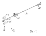
- die Kanülenanordnung nach Gebrauch mit Schlauch, Schlauchklemme und Luer-Adapter.
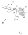
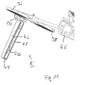
- In den Figuren, in denen gleiche Elemente mit gleichen Bezugszeichen versehen sind, ist eine Kanülenanordnung 10 dargestellt, die eine Portkanüle 12 mit Handhabe 14 sowie Schutzeinrichtung 16 umfasst. Die Portkanüle 12 umfasst einen proximalen Abschnitt 18 und einen rechtwinklig zu diesem verlaufenden distalen Abschnitt 20, der distal eine geschliffene Spitze 22 aufweist, die in einen in einem Körper implantierten Port einstechbar ist, um ein Medikament zuzuführen.
- An das Ende des proximalen Abschnitts 18 der Kanüle 12 ist in gewohnter Weise ein Schlauch 24 aufschiebbar, der seinerseits durch eine Schlauchklemme 26 absperrbar bzw. freigebbar ist. Am Ende des Schlauchs 24 befindet sich im Ausführungsbeispiel ein Luer-Adapter 28 mit Drehverschluss.
- Die Handhabe 14 weist einen den proximalen Abschnitt 18 der Kanüle 12 umgebenden mittleren Abschnitt 30 auf, der im Ausführungsbeispiel quaderförmig ausgebildet ist. Von den Seitenflächen 32, 34 des Mittelabschnitts 30 gehen Flügel 36, 38 aus, die vorzugsweise zu dem Mittelabschnitt 30 verschenkbar sind, ohne dass dies ein zwingendes Merkmal darstellt. Unterseitig sind die Flügel 36, 38 strukturiert, um beim Fixieren der Kanüle 12 auf einer Patientenhaut eine flächige Auflage zu vermeiden.
- Im Ausführungsbeispiel ist integral mit der Handhabe 14 die Schutzeinrichtung 16 ausgebildet wie gespritzt, wobei zwischen dem Mittelabschnitt 30 und der Schutzeinrichtung 16 zum Verschwenken dieser ein Filmscharnier 40 verläuft, das sich senkrecht zu der Kanüle 12, also sowohl zu dem proximalen Abschnitt 38 als auch zu dem distalen Abschnitt 20 erstreckt. Ferner verläuft das Filmscharnier 40 parallel zu einer Ebene, die durch die Flügel 36, 38 in unverschwenktem Zustand aufgespannt ist, wie dies den Figuren zu entnehmen ist. Das Filmscharnier 40 gibt die Schwenkachse vor, die daher auch mit dem Bezugszeichen 40 gekennzeichnet wird, um die ein kanalförmiger Abschnitt 42 der Schutzeinrichtung 16 zu der Handhabe 14 hin bzw. weg von dieser verschwenkbar ist, wie nachstehend erläutert wird.
- Der kanalförmige Abschnitt 42 ist im Ausführungsbeispiel im Schnitt U-förmig und endseitig geschlossen (Stirnwandung 44) ausgebildet. Folglich weist der kanalförmige Abschnitt 42 Seitenwandungen 46, 48 sowie eine Bodenwandung 50 auf. Der kanalförmige Abschnitt 42, d. h. dessen Bodenwandung 50 geht in eine flächige Erweiterung 52 über, die über das Filmscharnier 40 mit dem mittleren Abschnitt 30 der Handhabe 14 verbunden ist.
- Die flächige Erweiterung 52 ist auf ihrer Unterseite 54 strukturiert, um beim Setzen der Kanüle 12, d. h. Einstechen des distalen Abschnitts 20 der Kanüle als Positionierhilfe zu dienen. So steht dem Nutzer beim Setzen, bei dem die Flügel 36, 38 aufeinander liegen, um ein Hantieren zu ermöglichen, eine relativ große Fläche zur Verfügung, um den distalen Abschnitt 20 führen zu können, damit ein sicheres Einstechen der Spitze 22 in den Port ermöglicht wird.
- Von den Innenflächen der Seitenwandung 46, 48 und des kanalförmigen Abschnitts 42 ragen paarweise angeordnete Vorsprünge 56, 58 bzw. 60, 62 ab, die beabstandet zur Innenfläche 64 der Bodenwandung 50 verlaufen und zu diesem einen lichten Abstand aufweisen, der es ermöglicht, dass in dem so gebildeten Zwischenraum der distale Abschnitt 20 der Kanüle 12 positionierbar und über die Vorsprünge 56, 58 bzw. 60, 62 fixierbar ist.
- Wie insbesondere aus der
Fig. 7 ersichtlich ist, sind die äußeren, also öffnungsseitig verlaufenden Oberseiten 66, 68, 70, 72 der Vorsprünge 56, 58, 60, 62 in Richtung der Bodenfläche 64 geneigt, um ein Einführen des distalen Abschnitts 20 zu erleichtern. Bodenflächenseitig sollten die Vorsprünge 56, 58, 60, 62 in etwa parallel zur Bodenfläche verlaufen, so dass die Vorsprünge, 56, 58, 60, 62 wandseitig eine größere Stärke als endseitig aufweisen. Unabhängig hiervon sollten die Vorsprünge 56, 58, 60, 62 so dimensioniert und angeordnet sein, dass beim Einwirken einer Kraft in Richtung der Bodenfläche 64 eine größere Beweglichkeit gegeben ist als bei entgegengerichtet wirkender Kraft. - Des Weiteren verläuft in der Bodenwandung 50 des kanalförmigen Abschnitts 42 eine Aussparung 74, der ein von dem mittleren Abschnitt 30 der Handhabe 14 senkrecht abragender Vorsprung 76 zugeordnet ist.
- Die Funktion der Schutzeinrichtung 16 bzw. deren Positionierung bei der Herstellung, im Nutzzustand sowie nach der Benutzung der Kanüle 12 ergeben sich aus den
Fig. 1 bis 5 bzw. 6 bis 8 bzw. 9 bis 12. - So ist in den
Fig. 1 bis 5 die Schutzeinrichtung 16 im Herstellungszustand dargestellt, bei dem die Schutzeinrichtung 16 zusammen mit der Handhabe 14 die Kanüle 12, d. h. deren proximaler Abschnitt 18 und bereichsweise der distale Abschnitt 20 umspritzt werden. In diesem Zustand verläuft die Längsachse der Schutzreinrichtung 16 entlang der von den Flügeln 36, 38 gemeinsam aufgespannten Ebene. - Soll die Kanülenanordnung 10 genutzt werden, so wird die Schutzeinrichtung 16 um das die Schwenkachse vorgebende Filmscharnier 40 in Richtung der Handhabe 14 verschwenkt, damit der Vorsprung 76, der von der Außenseite des mittleren oder Mittelabschnitts 30 der Handhabe 14 abragt, einrasten kann, so dass eine Behinderung durch die Schutzeinrichtung 16 bei der Nutzung der Kanülenanordnung 10 nicht erfolgen kann.
- Anstelle einer entsprechenden Rastverbindung kann die Schutzeinrichtung 16 mit der Handhabe 14 auch über ein Scharnier mit sogenannter Totpunktlage verbunden werden. Dies bedeutet, dass dann, wenn die Schutzeinrichtung 16 zu den Flügeln 36, 38 verschwenkt ist, das Scharnier eine Totpunktlage einnimmt und somit die Schutzeinrichtung 16 nicht unkontrolliert verschwenkt werden kann.
- Der Nutzzustand der Kanülenanordnung 10 ergibt sich aus den
Fig. 6 bis 8 . Man kann erkennen, dass der als Schutzkappe zu bezeichnende kanalförmige Abschnitt 42 der Schutzeinrichtung 16 mit der Außenseite 78 der Bodenwandung 50 auf der oberen Außenfläche 80 des Mittelabschnittes 30 der Handhabe 14 liegt, wobei der Vorsprung 76 in die Aussparung 74 eingreift. Auch die flächige Erstreckung 52 der Schutzeinrichtung 16 erstreckt sich entlang der Fläche 80, wie dieFig. 6 und7 verdeutlichen. Dabei ist die strukturierte Fläche 54 der Erstreckung 52 außenliegend. Ferner sind das Filmscharnier 40 und die flächige Erstreckung 52 derart angeordnet bzw. ausgebildet, dass letztere von dem distalen Abschnitt 20 der Kanüle 12 durchsetzt wird. Gegebenenfalls kann ein mittiges Durchsetzen erfolgen. - Soll die Portkanüle nunmehr gesetzt werden, werden die Flügel 36, 38 zusammengeklappt, um also bereichsweise aufeinanderzuliegen, um die Kanülenanordnung 10 auf einen Bereich eines Patienten auszurichten, in dem ein Einstechen in einen Port erfolgen kann. Die flächige Erstreckung 52 dient dabei als Manövrierhilfe, so dass positionsgenaues Ausrichten des distalen Abschnitts 22 auf den Port, d. h. zum Durchstechen der Membran erfolgen kann. Ist die Kanüle gesetzt, so werden die Flügel 36, 38 zurückalso auseinandergeklappt und auf der Haut des Patienten mittels eines Pflasters fixiert. Da die Dimensionierung, d. h. flächige Erstreckung der Flügel 36, 38 ausschließlich auf die sichere Handhabung der Kanülenanordnung 10 und nicht auf die Länge des distalen Abschnitts 20 abgestimmt sein muss, kann eine relativ geringe Flächenerstreckung gewählt werden, wodurch eine Reizung der Haut vermindert wird.
- Nachdem das Medikament über den distalen Abschnitt 20 zugeführt worden ist, wird die Kanüle 12 entfernt und sodann die Schutzeinrichtung 16 um das Filmscharnier 40 in den zeichnerischen Darstellungen entgegen dem Uhrzeigersinn verschwenkt, bis der distale Abschnitt 20 die Öffnung des kanalförmigen Abschnitts 42 durchsetzt und die Vorsprünge 56, 58, 60, 62 überwindet, um in den Zwischenraum zwischen diesen und der Bodenfläche 64 des kanalförmigen Abschnitts 42 zu gelangen. In dieser Position ist der distale Abschnitt 20 fixiert, da auch dann, wenn auf den kanalförmigen Abschnitt 42 eine Kraft zum Verschwenken um das Filmscharnier 40, also in den zeichnerischen Darstellungen im Uhrzeigersinn erfolgen sollte, die Vorsprünge 56, 58, 60, 62 aufgrund der Dimensionierung und Gestaltung nicht überwunden werden können, so dass eine sichere Abdeckung des benutzten distalen Kanülenabschnitts 20 gewährleistet ist.
- Es erfolgt ein Verrasten zwischen der Bodenfläche 64 und den Vorsprüngen 56, 58, 60, 62, deren Erstreckung quer zur Längsachse des Abschnitts 42 derart ist, dass der vorhandene Freiraum zwischen den Vorsprüngen 56, 58, 60, 62 bzw. eines Vorsprungs und der Seitenwandung, von der der Vorsprung nicht ausgeht, so abgestimmt ist, dass ein lichter Abstand gegeben ist, der kleiner als Durchmesser des distalen Abschnitts der Kanüle 12 ist.
- Anstelle eines im Schnitt U-förmigen kanalförmigen Abschnitts 42 kann auch eine andere Geometrie gewählt werden. Gleiches gilt bezüglich der Vorsprünge und deren Gestaltung, ohne dass die Erfindung verlassen wird. Ausschlaggebend ist allein, dass nach Benutzen der Kanüle 12 deren distaler Abschnitt 20 sicher in der Schutzeinrichtung 16, d. h. dem entsprechend gestalteten kanalförmigen Abschnitt 42 fixiert ist, ohne dass ein ungewolltes Verschwenken dieses erfolgen kann, da der verrastete distale Abschnitt 20 ein solches verhindert. Anstelle eines Verrastens kann auch ein Festklemmen erfolgen.
Claims (15)
- Kanülenanordnung (10) umfassend eine Kanüle (12) mit einem proximalen Abschnitt (18) und einem distalen Abschnitt (20), die zueinander einen rechten oder einen im Wesentlichen rechten Winkel einschließen, eine von dem proximalen Abschnitt ausgehende Handhabe (14) umfassend einen den proximalen Abschnitt aufnehmenden Mittelabschnitt (30) mit von diesem ausgehenden und vorzugsweise zu diesem verschwenkbaren Flügeln (36, 38) sowie eine nach Gebrauch der Kanüle den distalen Abschnitt abdeckende Schutzeinrichtung (16), die verschwenkbar an der Handhabe (14) angelenkt und um eine senkrecht zum proximalen Kanülenabschnitt (18) sowie parallel zu einer von den in einer Ebene verlaufenden Flügeln (36, 38) aufgespannten Ebene verlaufende Achse (40) schwenkbar ist und einen kanalförmigen Abschnitt (42) zur Aufnahme des distalen Abschnitts (20) der Kanüle (12) aufweist und bei von dem kanalförmigen Abschnitt aufgenommenen distalen Kanülenabschnitt dieser in dem kanalförmigen Abschnitt fixiert ist,
dadurch gekennzeichnet,
dass die Schutzeinrichtung in Nutzposition der Kanüle (12) in einer sich entlang dem Mittelabschnitt (30) der Handhabe (14) erstreckenden Stellung fixiert ist. - Kanülenanordnung nach Anspruch 1,
dadurch gekennzeichnet,
dass in der Nutzposition der Kanüle (12) die Bodenwandung (50) der Schutzeinrichtung (16) auf dem Mittelabschnitt (30) der Handhabe (14) fixiert ist. - Kanülenanordnung nach Anspruch 1 oder 2,
dadurch gekennzeichnet,
dass Bodenwandung (50) des kanalförmigen Abschnitts (42) der Schutzeinrichtung (16) ein erstes Rastmittel (74) aufweist, dem ein in dem Mittelabschnitt (30) der Handhabe (14) vorhandenes zweites Rastmittel (76) zum Verrasten des kanalförmigen Abschnitts zugeordnet ist. - Kanülenanordnung nach Anspruch 1 oder 2,
dadurch gekennzeichnet,
dass die Schutzeinrichtung (16) mit der Handhabe (14) über ein Scharnier verbunden ist, mittels dessen die Schutzeinrichtung in Nutzposition in einer Totpunktlage und entlang der Handhabe verlaufend fixierbar ist. - Kanülenanordnung nach zumindest Anspruch 3,
dadurch gekennzeichnet,
dass die Bodenwandung (50) zumindest in einem Längsbereich parallel zu der Achse verläuft und das Rastmittel (74) aufweist. - Kanülenanordnung nach zumindest Anspruch 3,
dadurch gekennzeichnet,
dass das erste Rastmittel eine Aussparung (74) und das zweite Rastmittel ein Vorsprung (76) ist oder umgekehrt. - Kanülenanordnung nach zumindest einem der vorhergehenden Ansprüche,
dadurch gekennzeichnet,
dass die Achse (40) durch ein Filmscharnier gebildet ist, wobei vorzugsweise das Filmscharnier zwischen dem Mittelabschnitt (30) der Handhabe (14) und einer proximalen flächigen Erweiterung (52) der Schutzeinrichtung (16) verläuft, die in die Bodenwandung (50) der Schutzeinrichtung übergeht und quer zum proximalen Kanülenabschnitt (18) vorzugsweise eine größere Erstreckung als die Bodenwandung (50) aufweist. - Kanülenanordnung nach zumindest einem der vorhergehenden Ansprüche,
dadurch gekennzeichnet,
dass bei auf dem Mittelabschnitt (30) der Handhabe (14) fixiertem bzw. entlang diesem sich erstreckendem kanalförmigen Abschnitt (42) dessen Bodenwandung (50) und die flächige Erstreckung (52) entlang Oberseite des Mittelabschnitts (30) bzw. auf dieser liegend verläuft. - Kanülenanordnung nach zumindest einem der vorhergehenden Ansprüche,
dadurch gekennzeichnet,
dass bei entlang der Außenfläche des Mittelabschnitts (30) verlaufender flächiger Erweiterung (52) diese von der Längsachse des distalen Kanülenabschnitts (20) durchsetzt ist. - Kanülenanordnung nach zumindest einem der vorhergehenden Ansprüche,
dadurch gekennzeichnet,
dass die Längsachse des distalen Kanülenabschnitts (20) die flächige Erstreckung (52) vorzugsweise mittig oder in etwa mittig durchsetzt. - Kanülenanordnung nach zumindest einem der vorhergehenden Ansprüche,
dadurch gekennzeichnet,
dass der kanalförmige Abschnitt (42) zumindest einen inneren Vorsprung (56, 58, 60, 62) aufweist, der bei in dem kanalförmigen Abschnitt fixiertem distalen Kanülenabschnitt (20) von diesem hintergriffen ist, wobei insbesondere der zumindest eine innere Vorsprung (56, 58, 60, 62) von einer ersten Innenseitenfläche des kanalförmigen Abschnitts (42) ausgeht und zumindest abschnittsöffnungsseitig in Richtung Bodenfläche (64) des kanalförmigen Abschnitts (42) geneigt verläuft. - Kanülenanordnung nach zumindest einem der vorhergehenden Ansprüche,
dadurch gekennzeichnet,
dass der zumindest eine innere Vorsprung (56, 58, 60, 62) entlang der Bodenfläche und quer zur Längsachse des kanalförmigen Abschnitts (42) betrachtet zur gegenüberliegenden zweiten Innenfläche und/oder zu einem von dieser ausgehenden zweiten inneren Vorsprung einen lichten Abstand aufweist, der kleiner als Durchmesser des distalen Kanülenabschnitts (20) ist. - Kanülenanordnung nach zumindest einem der vorhergehenden Ansprüche,
dadurch gekennzeichnet,
dass zwei Paar von inneren Vorsprüngen (56, 58, 60, 62) vorgesehen sind, wobei einer der Vorsprünge eines Paares von der ersten Seiteninnenfläche und der andere Vorsprung von der zweiten Seiteninnenfläche ausgeht. - Kanülenanordnung nach zumindest einem der vorhergehenden Ansprüche,
dadurch gekennzeichnet,
dass der innere Vorsprung (56, 58) in Richtung der Bodenfläche (64) beweglicher als in Richtung der Öffnungsseite des kanalförmigen Abschnitts (42) ist. - Kanülenanordnung nach zumindest einem der vorhergehenden Ansprüche,
dadurch gekennzeichnet,
dass der kanalförmige Abschnitt (42) senkrecht zur Längsachse betrachtet im Schnitt eine U-Form aufweist oder eine offene kreisähnliche Geometrie aufweist.
Applications Claiming Priority (1)
| Application Number | Priority Date | Filing Date | Title |
|---|---|---|---|
| DE200810002854 DE102008002854A1 (de) | 2008-05-15 | 2008-05-15 | Kanülenanordnung |
Publications (2)
| Publication Number | Publication Date |
|---|---|
| EP2119462A1 true EP2119462A1 (de) | 2009-11-18 |
| EP2119462B1 EP2119462B1 (de) | 2012-07-04 |
Family
ID=40941980
Family Applications (1)
| Application Number | Title | Priority Date | Filing Date |
|---|---|---|---|
| EP20090160356 Active EP2119462B1 (de) | 2008-05-15 | 2009-05-15 | Kanülenanordnung |
Country Status (2)
| Country | Link |
|---|---|
| EP (1) | EP2119462B1 (de) |
| DE (1) | DE102008002854A1 (de) |
Cited By (3)
| Publication number | Priority date | Publication date | Assignee | Title |
|---|---|---|---|---|
| DE202010000443U1 (de) | 2010-03-23 | 2011-08-08 | Süddeutsche Feinmechanik GmbH | Kanülenanordnung |
| US20180015231A1 (en) * | 2015-03-27 | 2018-01-18 | Terumo Kabushiki Kaisha | Injection needle assembly, and drug injection device |
| CN112657014A (zh) * | 2014-03-28 | 2021-04-16 | 百深公司 | 用于注射药物的皮下输注设备 |
Citations (11)
| Publication number | Priority date | Publication date | Assignee | Title |
|---|---|---|---|---|
| US5405332A (en) * | 1994-03-28 | 1995-04-11 | Opalek; A. Allen | Shield apparatus for syringe needle |
| WO2002045574A2 (en) | 2000-12-08 | 2002-06-13 | Tyco Healthcare Group Lp | Safety shield for medical needles |
| EP1256355A1 (de) * | 2001-05-11 | 2002-11-13 | Harmac Medical Products, Inc. | Kombination aus Nadelanordnung und Nadelabschirmung |
| US6500155B2 (en) | 2001-02-13 | 2002-12-31 | Churchill Medical Systems, Inc. | Safety angled indwelling needle and a protective shield for a safety angled indwelling needle |
| FR2847478A1 (fr) * | 2002-11-21 | 2004-05-28 | Vygon | Dispositif anti-pique pour aiguille d'injection coudee |
| WO2005000377A2 (en) * | 2003-06-18 | 2005-01-06 | Command Medical Products Incorporated | Infusion device with safety guard |
| US6921388B2 (en) | 2002-11-04 | 2005-07-26 | Becton Dickinson Co | Needle assembly |
| WO2005120624A1 (fr) * | 2004-05-07 | 2005-12-22 | Laboratoires Perouse | Dispositif d'injection a mecanisme d'extraction |
| US20060030825A1 (en) | 2002-02-04 | 2006-02-09 | Benlan, Inc. | Safety needle device |
| DE69935347T2 (de) | 1998-11-05 | 2007-06-21 | C.R. Bard, Inc. | Sicherheitsgehäuse für injektionsspritze |
| JP2007195827A (ja) | 2006-01-27 | 2007-08-09 | Nipro Corp | 湾曲部を有する安全針組立体 |
-
2008
- 2008-05-15 DE DE200810002854 patent/DE102008002854A1/de not_active Withdrawn
-
2009
- 2009-05-15 EP EP20090160356 patent/EP2119462B1/de active Active
Patent Citations (11)
| Publication number | Priority date | Publication date | Assignee | Title |
|---|---|---|---|---|
| US5405332A (en) * | 1994-03-28 | 1995-04-11 | Opalek; A. Allen | Shield apparatus for syringe needle |
| DE69935347T2 (de) | 1998-11-05 | 2007-06-21 | C.R. Bard, Inc. | Sicherheitsgehäuse für injektionsspritze |
| WO2002045574A2 (en) | 2000-12-08 | 2002-06-13 | Tyco Healthcare Group Lp | Safety shield for medical needles |
| US6500155B2 (en) | 2001-02-13 | 2002-12-31 | Churchill Medical Systems, Inc. | Safety angled indwelling needle and a protective shield for a safety angled indwelling needle |
| EP1256355A1 (de) * | 2001-05-11 | 2002-11-13 | Harmac Medical Products, Inc. | Kombination aus Nadelanordnung und Nadelabschirmung |
| US20060030825A1 (en) | 2002-02-04 | 2006-02-09 | Benlan, Inc. | Safety needle device |
| US6921388B2 (en) | 2002-11-04 | 2005-07-26 | Becton Dickinson Co | Needle assembly |
| FR2847478A1 (fr) * | 2002-11-21 | 2004-05-28 | Vygon | Dispositif anti-pique pour aiguille d'injection coudee |
| WO2005000377A2 (en) * | 2003-06-18 | 2005-01-06 | Command Medical Products Incorporated | Infusion device with safety guard |
| WO2005120624A1 (fr) * | 2004-05-07 | 2005-12-22 | Laboratoires Perouse | Dispositif d'injection a mecanisme d'extraction |
| JP2007195827A (ja) | 2006-01-27 | 2007-08-09 | Nipro Corp | 湾曲部を有する安全針組立体 |
Cited By (7)
| Publication number | Priority date | Publication date | Assignee | Title |
|---|---|---|---|---|
| DE202010000443U1 (de) | 2010-03-23 | 2011-08-08 | Süddeutsche Feinmechanik GmbH | Kanülenanordnung |
| EP2368596A1 (de) | 2010-03-23 | 2011-09-28 | Süddeutsche Feinmechanik GmbH | Kanülenanordnung |
| CN112657014A (zh) * | 2014-03-28 | 2021-04-16 | 百深公司 | 用于注射药物的皮下输注设备 |
| JP2022186913A (ja) * | 2014-03-28 | 2022-12-15 | 武田薬品工業株式会社 | 医薬物を注入するための皮下注入装置 |
| JP7408360B2 (ja) | 2014-03-28 | 2024-01-05 | 武田薬品工業株式会社 | 医薬物を注入するための皮下注入装置 |
| CN112657014B (zh) * | 2014-03-28 | 2024-12-17 | 武田药品工业株式会社 | 用于注射药物的皮下输注设备 |
| US20180015231A1 (en) * | 2015-03-27 | 2018-01-18 | Terumo Kabushiki Kaisha | Injection needle assembly, and drug injection device |
Also Published As
| Publication number | Publication date |
|---|---|
| DE102008002854A1 (de) | 2009-11-19 |
| EP2119462B1 (de) | 2012-07-04 |
Similar Documents
| Publication | Publication Date | Title |
|---|---|---|
| DE60304681T2 (de) | Infusionsvorrichtung mit nadelschutzhülse | |
| EP1587419B1 (de) | Medizinische baugruppe sowie eine schutzvorrichtung, ein einstichelement und eine handhabungsvorrichtung für diese baugruppe | |
| DE10254443B4 (de) | Einsetzhilfe zum Einsetzen eines Katheterkopfes in ein organisches Gewebe | |
| DE69509781T2 (de) | Nadelschutz | |
| DE4234990C2 (de) | Trokarhülse | |
| EP1985264B1 (de) | Orthese | |
| EP2190507A1 (de) | Kanülenvorrichtung mit schwenkbarem nadelschutz | |
| EP2827924B1 (de) | Sicherheitsnadelvorrichtung, insbesondere zur punktion von in einem menschlichen oder tierischen körper subkutan implantierten port | |
| EP1646420A1 (de) | Einstechvorrichtung zum einstechen einer Injektionsnadel | |
| DE69100973T2 (de) | Wegwerf-einmalverwendbare Infusionsvorrichtung mit Kappe für die Nadel nach Verwendung. | |
| DE19518803A1 (de) | Faltbare Sicherheitsschutzvorrichtung für Nadeln medizinischer Spritzen | |
| DE112005001046B4 (de) | Injektionseinrichtung mit Ausziehmechanismus | |
| EP2119462B1 (de) | Kanülenanordnung | |
| EP0023580B1 (de) | Katheteransatz | |
| DE69102193T2 (de) | Schutzvorrichtung für eine Anschlussstelle für medizinische Zwecke. | |
| EP2995332B1 (de) | Sicherheitsvorrichtung für eine medizinische nadel | |
| EP3000501B1 (de) | Kanüle | |
| DE29908794U1 (de) | Kanüle, insbesondere zum Einführen in den Spinalkanal | |
| EP3999142B1 (de) | Schutzvorrichtung für das nadelrohr einer spritze | |
| WO2010046112A1 (de) | Kanüle mit schutzvorrichtung | |
| EP2368596B1 (de) | Kanülenanordnung | |
| EP4355390B1 (de) | Sicherheitskanülenanordnung | |
| EP2473323A1 (de) | Kürette | |
| EP4464346A1 (de) | Fixiervorrichtung zum fixieren eines katheters | |
| DE60206034T2 (de) | Spritze |
Legal Events
| Date | Code | Title | Description |
|---|---|---|---|
| PUAI | Public reference made under article 153(3) epc to a published international application that has entered the european phase |
Free format text: ORIGINAL CODE: 0009012 |
|
| AK | Designated contracting states |
Kind code of ref document: A1 Designated state(s): AT BE BG CH CY CZ DE DK EE ES FI FR GB GR HR HU IE IS IT LI LT LU LV MC MK MT NL NO PL PT RO SE SI SK TR |
|
| 17P | Request for examination filed |
Effective date: 20100511 |
|
| 17Q | First examination report despatched |
Effective date: 20100721 |
|
| GRAP | Despatch of communication of intention to grant a patent |
Free format text: ORIGINAL CODE: EPIDOSNIGR1 |
|
| GRAS | Grant fee paid |
Free format text: ORIGINAL CODE: EPIDOSNIGR3 |
|
| GRAA | (expected) grant |
Free format text: ORIGINAL CODE: 0009210 |
|
| AK | Designated contracting states |
Kind code of ref document: B1 Designated state(s): AT BE BG CH CY CZ DE DK EE ES FI FR GB GR HR HU IE IS IT LI LT LU LV MC MK MT NL NO PL PT RO SE SI SK TR |
|
| REG | Reference to a national code |
Ref country code: GB Ref legal event code: FG4D Free format text: NOT ENGLISH |
|
| REG | Reference to a national code |
Ref country code: CH Ref legal event code: EP |
|
| REG | Reference to a national code |
Ref country code: AT Ref legal event code: REF Ref document number: 564892 Country of ref document: AT Kind code of ref document: T Effective date: 20120715 |
|
| REG | Reference to a national code |
Ref country code: IE Ref legal event code: FG4D Free format text: LANGUAGE OF EP DOCUMENT: GERMAN |
|
| REG | Reference to a national code |
Ref country code: DE Ref legal event code: R096 Ref document number: 502009003985 Country of ref document: DE Effective date: 20120830 |
|
| REG | Reference to a national code |
Ref country code: NL Ref legal event code: VDEP Effective date: 20120704 |
|
| PG25 | Lapsed in a contracting state [announced via postgrant information from national office to epo] |
Ref country code: SI Free format text: LAPSE BECAUSE OF FAILURE TO SUBMIT A TRANSLATION OF THE DESCRIPTION OR TO PAY THE FEE WITHIN THE PRESCRIBED TIME-LIMIT Effective date: 20120704 |
|
| REG | Reference to a national code |
Ref country code: CH Ref legal event code: NV Representative=s name: LUCHS AND PARTNER PATENTANWAELTE, CH |
|
| REG | Reference to a national code |
Ref country code: LT Ref legal event code: MG4D Effective date: 20120704 |
|
| PG25 | Lapsed in a contracting state [announced via postgrant information from national office to epo] |
Ref country code: IS Free format text: LAPSE BECAUSE OF FAILURE TO SUBMIT A TRANSLATION OF THE DESCRIPTION OR TO PAY THE FEE WITHIN THE PRESCRIBED TIME-LIMIT Effective date: 20121104 Ref country code: LT Free format text: LAPSE BECAUSE OF FAILURE TO SUBMIT A TRANSLATION OF THE DESCRIPTION OR TO PAY THE FEE WITHIN THE PRESCRIBED TIME-LIMIT Effective date: 20120704 Ref country code: FI Free format text: LAPSE BECAUSE OF FAILURE TO SUBMIT A TRANSLATION OF THE DESCRIPTION OR TO PAY THE FEE WITHIN THE PRESCRIBED TIME-LIMIT Effective date: 20120704 Ref country code: HR Free format text: LAPSE BECAUSE OF FAILURE TO SUBMIT A TRANSLATION OF THE DESCRIPTION OR TO PAY THE FEE WITHIN THE PRESCRIBED TIME-LIMIT Effective date: 20120704 Ref country code: NO Free format text: LAPSE BECAUSE OF FAILURE TO SUBMIT A TRANSLATION OF THE DESCRIPTION OR TO PAY THE FEE WITHIN THE PRESCRIBED TIME-LIMIT Effective date: 20121004 Ref country code: CY Free format text: LAPSE BECAUSE OF FAILURE TO SUBMIT A TRANSLATION OF THE DESCRIPTION OR TO PAY THE FEE WITHIN THE PRESCRIBED TIME-LIMIT Effective date: 20120704 |
|
| PG25 | Lapsed in a contracting state [announced via postgrant information from national office to epo] |
Ref country code: PL Free format text: LAPSE BECAUSE OF FAILURE TO SUBMIT A TRANSLATION OF THE DESCRIPTION OR TO PAY THE FEE WITHIN THE PRESCRIBED TIME-LIMIT Effective date: 20120704 Ref country code: PT Free format text: LAPSE BECAUSE OF FAILURE TO SUBMIT A TRANSLATION OF THE DESCRIPTION OR TO PAY THE FEE WITHIN THE PRESCRIBED TIME-LIMIT Effective date: 20121105 Ref country code: LV Free format text: LAPSE BECAUSE OF FAILURE TO SUBMIT A TRANSLATION OF THE DESCRIPTION OR TO PAY THE FEE WITHIN THE PRESCRIBED TIME-LIMIT Effective date: 20120704 Ref country code: GR Free format text: LAPSE BECAUSE OF FAILURE TO SUBMIT A TRANSLATION OF THE DESCRIPTION OR TO PAY THE FEE WITHIN THE PRESCRIBED TIME-LIMIT Effective date: 20121005 Ref country code: SE Free format text: LAPSE BECAUSE OF FAILURE TO SUBMIT A TRANSLATION OF THE DESCRIPTION OR TO PAY THE FEE WITHIN THE PRESCRIBED TIME-LIMIT Effective date: 20120704 |
|
| PG25 | Lapsed in a contracting state [announced via postgrant information from national office to epo] |
Ref country code: NL Free format text: LAPSE BECAUSE OF FAILURE TO SUBMIT A TRANSLATION OF THE DESCRIPTION OR TO PAY THE FEE WITHIN THE PRESCRIBED TIME-LIMIT Effective date: 20120704 |
|
| RAP2 | Party data changed (patent owner data changed or rights of a patent transferred) |
Owner name: SFM MEDICAL DEVICES GMBH |
|
| PG25 | Lapsed in a contracting state [announced via postgrant information from national office to epo] |
Ref country code: DK Free format text: LAPSE BECAUSE OF FAILURE TO SUBMIT A TRANSLATION OF THE DESCRIPTION OR TO PAY THE FEE WITHIN THE PRESCRIBED TIME-LIMIT Effective date: 20120704 Ref country code: EE Free format text: LAPSE BECAUSE OF FAILURE TO SUBMIT A TRANSLATION OF THE DESCRIPTION OR TO PAY THE FEE WITHIN THE PRESCRIBED TIME-LIMIT Effective date: 20120704 Ref country code: ES Free format text: LAPSE BECAUSE OF FAILURE TO SUBMIT A TRANSLATION OF THE DESCRIPTION OR TO PAY THE FEE WITHIN THE PRESCRIBED TIME-LIMIT Effective date: 20121015 Ref country code: CZ Free format text: LAPSE BECAUSE OF FAILURE TO SUBMIT A TRANSLATION OF THE DESCRIPTION OR TO PAY THE FEE WITHIN THE PRESCRIBED TIME-LIMIT Effective date: 20120704 Ref country code: RO Free format text: LAPSE BECAUSE OF FAILURE TO SUBMIT A TRANSLATION OF THE DESCRIPTION OR TO PAY THE FEE WITHIN THE PRESCRIBED TIME-LIMIT Effective date: 20120704 |
|
| PLBE | No opposition filed within time limit |
Free format text: ORIGINAL CODE: 0009261 |
|
| STAA | Information on the status of an ep patent application or granted ep patent |
Free format text: STATUS: NO OPPOSITION FILED WITHIN TIME LIMIT |
|
| PG25 | Lapsed in a contracting state [announced via postgrant information from national office to epo] |
Ref country code: SK Free format text: LAPSE BECAUSE OF FAILURE TO SUBMIT A TRANSLATION OF THE DESCRIPTION OR TO PAY THE FEE WITHIN THE PRESCRIBED TIME-LIMIT Effective date: 20120704 Ref country code: IT Free format text: LAPSE BECAUSE OF FAILURE TO SUBMIT A TRANSLATION OF THE DESCRIPTION OR TO PAY THE FEE WITHIN THE PRESCRIBED TIME-LIMIT Effective date: 20120704 |
|
| 26N | No opposition filed |
Effective date: 20130405 |
|
| PG25 | Lapsed in a contracting state [announced via postgrant information from national office to epo] |
Ref country code: BG Free format text: LAPSE BECAUSE OF FAILURE TO SUBMIT A TRANSLATION OF THE DESCRIPTION OR TO PAY THE FEE WITHIN THE PRESCRIBED TIME-LIMIT Effective date: 20121004 |
|
| REG | Reference to a national code |
Ref country code: DE Ref legal event code: R097 Ref document number: 502009003985 Country of ref document: DE Effective date: 20130405 |
|
| BERE | Be: lapsed |
Owner name: SUDDEUTSCHE FEINMECHANIK G.M.B.H. Effective date: 20130531 |
|
| PG25 | Lapsed in a contracting state [announced via postgrant information from national office to epo] |
Ref country code: MC Free format text: LAPSE BECAUSE OF FAILURE TO SUBMIT A TRANSLATION OF THE DESCRIPTION OR TO PAY THE FEE WITHIN THE PRESCRIBED TIME-LIMIT Effective date: 20120704 |
|
| REG | Reference to a national code |
Ref country code: IE Ref legal event code: MM4A |
|
| PG25 | Lapsed in a contracting state [announced via postgrant information from national office to epo] |
Ref country code: BE Free format text: LAPSE BECAUSE OF NON-PAYMENT OF DUE FEES Effective date: 20130531 |
|
| PG25 | Lapsed in a contracting state [announced via postgrant information from national office to epo] |
Ref country code: IE Free format text: LAPSE BECAUSE OF NON-PAYMENT OF DUE FEES Effective date: 20130515 |
|
| PG25 | Lapsed in a contracting state [announced via postgrant information from national office to epo] |
Ref country code: MT Free format text: LAPSE BECAUSE OF FAILURE TO SUBMIT A TRANSLATION OF THE DESCRIPTION OR TO PAY THE FEE WITHIN THE PRESCRIBED TIME-LIMIT Effective date: 20120704 |
|
| REG | Reference to a national code |
Ref country code: CH Ref legal event code: PFA Owner name: SFM MEDICAL DEVICES GMBH, DE Free format text: FORMER OWNER: SUEDDEUTSCHE FEINMECHANIK GMBH, DE |
|
| REG | Reference to a national code |
Ref country code: DE Ref legal event code: R082 Ref document number: 502009003985 Country of ref document: DE Representative=s name: STOFFREGEN, HANS-HERBERT, DIPL.-PHYS. DR.RER.N, DE Ref country code: DE Ref legal event code: R081 Ref document number: 502009003985 Country of ref document: DE Owner name: SFM MEDICAL DEVICES GMBH, DE Free format text: FORMER OWNER: SUEDDEUTSCHE FEINMECHANIK GMBH, 63607 WAECHTERSBACH, DE |
|
| PG25 | Lapsed in a contracting state [announced via postgrant information from national office to epo] |
Ref country code: TR Free format text: LAPSE BECAUSE OF FAILURE TO SUBMIT A TRANSLATION OF THE DESCRIPTION OR TO PAY THE FEE WITHIN THE PRESCRIBED TIME-LIMIT Effective date: 20120704 |
|
| REG | Reference to a national code |
Ref country code: AT Ref legal event code: MM01 Ref document number: 564892 Country of ref document: AT Kind code of ref document: T Effective date: 20140515 |
|
| PG25 | Lapsed in a contracting state [announced via postgrant information from national office to epo] |
Ref country code: LU Free format text: LAPSE BECAUSE OF NON-PAYMENT OF DUE FEES Effective date: 20130515 Ref country code: HU Free format text: LAPSE BECAUSE OF FAILURE TO SUBMIT A TRANSLATION OF THE DESCRIPTION OR TO PAY THE FEE WITHIN THE PRESCRIBED TIME-LIMIT; INVALID AB INITIO Effective date: 20090515 Ref country code: MK Free format text: LAPSE BECAUSE OF FAILURE TO SUBMIT A TRANSLATION OF THE DESCRIPTION OR TO PAY THE FEE WITHIN THE PRESCRIBED TIME-LIMIT Effective date: 20120704 |
|
| PG25 | Lapsed in a contracting state [announced via postgrant information from national office to epo] |
Ref country code: AT Free format text: LAPSE BECAUSE OF NON-PAYMENT OF DUE FEES Effective date: 20140515 |
|
| REG | Reference to a national code |
Ref country code: FR Ref legal event code: CD Owner name: SFM MEDICAL DEVICES GMBH, DE Effective date: 20150907 |
|
| REG | Reference to a national code |
Ref country code: FR Ref legal event code: PLFP Year of fee payment: 8 |
|
| REG | Reference to a national code |
Ref country code: FR Ref legal event code: PLFP Year of fee payment: 9 |
|
| REG | Reference to a national code |
Ref country code: FR Ref legal event code: PLFP Year of fee payment: 10 |
|
| PGFP | Annual fee paid to national office [announced via postgrant information from national office to epo] |
Ref country code: GB Payment date: 20250312 Year of fee payment: 17 |
|
| PGFP | Annual fee paid to national office [announced via postgrant information from national office to epo] |
Ref country code: DE Payment date: 20250516 Year of fee payment: 17 |
|
| PGFP | Annual fee paid to national office [announced via postgrant information from national office to epo] |
Ref country code: FR Payment date: 20250528 Year of fee payment: 17 |
|
| PGFP | Annual fee paid to national office [announced via postgrant information from national office to epo] |
Ref country code: CH Payment date: 20250601 Year of fee payment: 17 |