EP2119545A2 - Procédé de recyclage de pneus - Google Patents
Procédé de recyclage de pneus Download PDFInfo
- Publication number
- EP2119545A2 EP2119545A2 EP07859001A EP07859001A EP2119545A2 EP 2119545 A2 EP2119545 A2 EP 2119545A2 EP 07859001 A EP07859001 A EP 07859001A EP 07859001 A EP07859001 A EP 07859001A EP 2119545 A2 EP2119545 A2 EP 2119545A2
- Authority
- EP
- European Patent Office
- Prior art keywords
- tires
- pyrolysis
- tire
- parts
- recovery
- Prior art date
- Legal status (The legal status is an assumption and is not a legal conclusion. Google has not performed a legal analysis and makes no representation as to the accuracy of the status listed.)
- Withdrawn
Links
- 238000000034 method Methods 0.000 title claims abstract description 68
- 238000000197 pyrolysis Methods 0.000 claims abstract description 74
- 238000011084 recovery Methods 0.000 claims abstract description 50
- 239000010920 waste tyre Substances 0.000 claims abstract description 39
- 239000002184 metal Substances 0.000 claims abstract description 26
- 229910052751 metal Inorganic materials 0.000 claims abstract description 26
- 230000005291 magnetic effect Effects 0.000 claims abstract description 25
- 238000010438 heat treatment Methods 0.000 claims abstract description 24
- 238000005979 thermal decomposition reaction Methods 0.000 claims abstract description 11
- 230000006698 induction Effects 0.000 claims abstract description 8
- 230000001939 inductive effect Effects 0.000 claims abstract description 5
- 238000007599 discharging Methods 0.000 claims description 22
- 239000000047 product Substances 0.000 claims description 16
- 239000012265 solid product Substances 0.000 claims description 6
- 229910001111 Fine metal Inorganic materials 0.000 claims description 5
- 238000001816 cooling Methods 0.000 abstract description 6
- 239000007789 gas Substances 0.000 description 19
- 230000006378 damage Effects 0.000 description 7
- 230000007613 environmental effect Effects 0.000 description 7
- IJGRMHOSHXDMSA-UHFFFAOYSA-N Atomic nitrogen Chemical compound N#N IJGRMHOSHXDMSA-UHFFFAOYSA-N 0.000 description 4
- 229910000831 Steel Inorganic materials 0.000 description 4
- 238000012545 processing Methods 0.000 description 4
- 239000010959 steel Substances 0.000 description 4
- XLYOFNOQVPJJNP-UHFFFAOYSA-N water Substances O XLYOFNOQVPJJNP-UHFFFAOYSA-N 0.000 description 4
- 238000011027 product recovery Methods 0.000 description 3
- 230000005417 remagnetization Effects 0.000 description 3
- 239000007787 solid Substances 0.000 description 3
- 239000002699 waste material Substances 0.000 description 3
- 238000010276 construction Methods 0.000 description 2
- 125000004122 cyclic group Chemical group 0.000 description 2
- 239000002360 explosive Substances 0.000 description 2
- 230000001965 increasing effect Effects 0.000 description 2
- 238000004519 manufacturing process Methods 0.000 description 2
- 229910052757 nitrogen Inorganic materials 0.000 description 2
- 230000001473 noxious effect Effects 0.000 description 2
- 230000002265 prevention Effects 0.000 description 2
- 238000007789 sealing Methods 0.000 description 2
- 238000004804 winding Methods 0.000 description 2
- OKTJSMMVPCPJKN-UHFFFAOYSA-N Carbon Chemical group [C] OKTJSMMVPCPJKN-UHFFFAOYSA-N 0.000 description 1
- XEEYBQQBJWHFJM-UHFFFAOYSA-N Iron Chemical group [Fe] XEEYBQQBJWHFJM-UHFFFAOYSA-N 0.000 description 1
- QVGXLLKOCUKJST-UHFFFAOYSA-N atomic oxygen Chemical compound [O] QVGXLLKOCUKJST-UHFFFAOYSA-N 0.000 description 1
- 239000011324 bead Substances 0.000 description 1
- 230000015572 biosynthetic process Effects 0.000 description 1
- 238000007664 blowing Methods 0.000 description 1
- 239000003575 carbonaceous material Substances 0.000 description 1
- 235000009508 confectionery Nutrition 0.000 description 1
- 238000005520 cutting process Methods 0.000 description 1
- 230000007423 decrease Effects 0.000 description 1
- 230000003247 decreasing effect Effects 0.000 description 1
- 238000013461 design Methods 0.000 description 1
- 230000006866 deterioration Effects 0.000 description 1
- 238000011161 development Methods 0.000 description 1
- KZHJGOXRZJKJNY-UHFFFAOYSA-N dioxosilane;oxo(oxoalumanyloxy)alumane Chemical compound O=[Si]=O.O=[Si]=O.O=[Al]O[Al]=O.O=[Al]O[Al]=O.O=[Al]O[Al]=O KZHJGOXRZJKJNY-UHFFFAOYSA-N 0.000 description 1
- 230000005611 electricity Effects 0.000 description 1
- 238000004880 explosion Methods 0.000 description 1
- 230000005294 ferromagnetic effect Effects 0.000 description 1
- 239000003302 ferromagnetic material Substances 0.000 description 1
- 238000010304 firing Methods 0.000 description 1
- 239000012634 fragment Substances 0.000 description 1
- 239000000446 fuel Substances 0.000 description 1
- 230000005484 gravity Effects 0.000 description 1
- 239000011810 insulating material Substances 0.000 description 1
- 239000000463 material Substances 0.000 description 1
- 238000002844 melting Methods 0.000 description 1
- 230000008018 melting Effects 0.000 description 1
- 239000000203 mixture Substances 0.000 description 1
- 238000012986 modification Methods 0.000 description 1
- 230000004048 modification Effects 0.000 description 1
- 229910052863 mullite Inorganic materials 0.000 description 1
- 239000001301 oxygen Substances 0.000 description 1
- 229910052760 oxygen Inorganic materials 0.000 description 1
- 238000003825 pressing Methods 0.000 description 1
- 238000010791 quenching Methods 0.000 description 1
- 230000000171 quenching effect Effects 0.000 description 1
- 238000004064 recycling Methods 0.000 description 1
- 238000000926 separation method Methods 0.000 description 1
- 238000003860 storage Methods 0.000 description 1
Images
Classifications
-
- B—PERFORMING OPERATIONS; TRANSPORTING
- B29—WORKING OF PLASTICS; WORKING OF SUBSTANCES IN A PLASTIC STATE IN GENERAL
- B29B—PREPARATION OR PRETREATMENT OF THE MATERIAL TO BE SHAPED; MAKING GRANULES OR PREFORMS; RECOVERY OF PLASTICS OR OTHER CONSTITUENTS OF WASTE MATERIAL CONTAINING PLASTICS
- B29B17/00—Recovery of plastics or other constituents of waste material containing plastics
- B29B17/02—Separating plastics from other materials
- B29B17/0206—Selectively separating reinforcements from matrix material by destroying the interface bound before disintegrating the matrix to particles or powder, e.g. from tires or belts
- B29B17/021—Selectively separating reinforcements from matrix material by destroying the interface bound before disintegrating the matrix to particles or powder, e.g. from tires or belts using local heating of the reinforcement
-
- C—CHEMISTRY; METALLURGY
- C10—PETROLEUM, GAS OR COKE INDUSTRIES; TECHNICAL GASES CONTAINING CARBON MONOXIDE; FUELS; LUBRICANTS; PEAT
- C10B—DESTRUCTIVE DISTILLATION OF CARBONACEOUS MATERIALS FOR PRODUCTION OF GAS, COKE, TAR, OR SIMILAR MATERIALS
- C10B19/00—Heating of coke ovens by electrical means
-
- C—CHEMISTRY; METALLURGY
- C10—PETROLEUM, GAS OR COKE INDUSTRIES; TECHNICAL GASES CONTAINING CARBON MONOXIDE; FUELS; LUBRICANTS; PEAT
- C10B—DESTRUCTIVE DISTILLATION OF CARBONACEOUS MATERIALS FOR PRODUCTION OF GAS, COKE, TAR, OR SIMILAR MATERIALS
- C10B53/00—Destructive distillation, specially adapted for particular solid raw materials or solid raw materials in special form
- C10B53/07—Destructive distillation, specially adapted for particular solid raw materials or solid raw materials in special form of solid raw materials consisting of synthetic polymeric materials, e.g. tyres
-
- B—PERFORMING OPERATIONS; TRANSPORTING
- B29—WORKING OF PLASTICS; WORKING OF SUBSTANCES IN A PLASTIC STATE IN GENERAL
- B29B—PREPARATION OR PRETREATMENT OF THE MATERIAL TO BE SHAPED; MAKING GRANULES OR PREFORMS; RECOVERY OF PLASTICS OR OTHER CONSTITUENTS OF WASTE MATERIAL CONTAINING PLASTICS
- B29B17/00—Recovery of plastics or other constituents of waste material containing plastics
- B29B17/04—Disintegrating plastics, e.g. by milling
- B29B17/0412—Disintegrating plastics, e.g. by milling to large particles, e.g. beads, granules, flakes, slices
-
- B—PERFORMING OPERATIONS; TRANSPORTING
- B29—WORKING OF PLASTICS; WORKING OF SUBSTANCES IN A PLASTIC STATE IN GENERAL
- B29B—PREPARATION OR PRETREATMENT OF THE MATERIAL TO BE SHAPED; MAKING GRANULES OR PREFORMS; RECOVERY OF PLASTICS OR OTHER CONSTITUENTS OF WASTE MATERIAL CONTAINING PLASTICS
- B29B17/00—Recovery of plastics or other constituents of waste material containing plastics
- B29B17/04—Disintegrating plastics, e.g. by milling
- B29B2017/0424—Specific disintegrating techniques; devices therefor
- B29B2017/0496—Pyrolysing the materials
-
- B—PERFORMING OPERATIONS; TRANSPORTING
- B29—WORKING OF PLASTICS; WORKING OF SUBSTANCES IN A PLASTIC STATE IN GENERAL
- B29C—SHAPING OR JOINING OF PLASTICS; SHAPING OF MATERIAL IN A PLASTIC STATE, NOT OTHERWISE PROVIDED FOR; AFTER-TREATMENT OF THE SHAPED PRODUCTS, e.g. REPAIRING
- B29C35/00—Heating, cooling or curing, e.g. crosslinking or vulcanising; Apparatus therefor
- B29C35/02—Heating or curing, e.g. crosslinking or vulcanizing during moulding, e.g. in a mould
- B29C35/08—Heating or curing, e.g. crosslinking or vulcanizing during moulding, e.g. in a mould by wave energy or particle radiation
- B29C35/0805—Heating or curing, e.g. crosslinking or vulcanizing during moulding, e.g. in a mould by wave energy or particle radiation using electromagnetic radiation
- B29C2035/0811—Heating or curing, e.g. crosslinking or vulcanizing during moulding, e.g. in a mould by wave energy or particle radiation using electromagnetic radiation using induction
-
- B—PERFORMING OPERATIONS; TRANSPORTING
- B29—WORKING OF PLASTICS; WORKING OF SUBSTANCES IN A PLASTIC STATE IN GENERAL
- B29L—INDEXING SCHEME ASSOCIATED WITH SUBCLASS B29C, RELATING TO PARTICULAR ARTICLES
- B29L2030/00—Pneumatic or solid tyres or parts thereof
-
- Y—GENERAL TAGGING OF NEW TECHNOLOGICAL DEVELOPMENTS; GENERAL TAGGING OF CROSS-SECTIONAL TECHNOLOGIES SPANNING OVER SEVERAL SECTIONS OF THE IPC; TECHNICAL SUBJECTS COVERED BY FORMER USPC CROSS-REFERENCE ART COLLECTIONS [XRACs] AND DIGESTS
- Y02—TECHNOLOGIES OR APPLICATIONS FOR MITIGATION OR ADAPTATION AGAINST CLIMATE CHANGE
- Y02P—CLIMATE CHANGE MITIGATION TECHNOLOGIES IN THE PRODUCTION OR PROCESSING OF GOODS
- Y02P20/00—Technologies relating to chemical industry
- Y02P20/141—Feedstock
- Y02P20/143—Feedstock the feedstock being recycled material, e.g. plastics
-
- Y—GENERAL TAGGING OF NEW TECHNOLOGICAL DEVELOPMENTS; GENERAL TAGGING OF CROSS-SECTIONAL TECHNOLOGIES SPANNING OVER SEVERAL SECTIONS OF THE IPC; TECHNICAL SUBJECTS COVERED BY FORMER USPC CROSS-REFERENCE ART COLLECTIONS [XRACs] AND DIGESTS
- Y02—TECHNOLOGIES OR APPLICATIONS FOR MITIGATION OR ADAPTATION AGAINST CLIMATE CHANGE
- Y02W—CLIMATE CHANGE MITIGATION TECHNOLOGIES RELATED TO WASTEWATER TREATMENT OR WASTE MANAGEMENT
- Y02W30/00—Technologies for solid waste management
- Y02W30/50—Reuse, recycling or recovery technologies
- Y02W30/52—Mechanical processing of waste for the recovery of materials, e.g. crushing, shredding, separation or disassembly
-
- Y—GENERAL TAGGING OF NEW TECHNOLOGICAL DEVELOPMENTS; GENERAL TAGGING OF CROSS-SECTIONAL TECHNOLOGIES SPANNING OVER SEVERAL SECTIONS OF THE IPC; TECHNICAL SUBJECTS COVERED BY FORMER USPC CROSS-REFERENCE ART COLLECTIONS [XRACs] AND DIGESTS
- Y02—TECHNOLOGIES OR APPLICATIONS FOR MITIGATION OR ADAPTATION AGAINST CLIMATE CHANGE
- Y02W—CLIMATE CHANGE MITIGATION TECHNOLOGIES RELATED TO WASTEWATER TREATMENT OR WASTE MANAGEMENT
- Y02W30/00—Technologies for solid waste management
- Y02W30/50—Reuse, recycling or recovery technologies
- Y02W30/62—Plastics recycling; Rubber recycling
Definitions
- the present invention relates to the field of the processing and recovery of tires, mainly waste tires, by their thermal decomposition and may be practiced for waste tire pyrolysis, in particular, for the pyrolysis of waste tires which are previously divided into parts.
- the pyrolysis gases enter the "dead space" of feeding means of the recovery device which dead space has a volume equal to that of at least one tire and, during the return motion of the feeding means, the pyrolysis gases may emit to the atmosphere. This may result in the deterioration of the ecological situation and constitutes danger to the operating personnel.
- the appropriate measures should be taken such as, for example, blowing the feeding means and sealing means with indifferent gas or sweet gas or water steam. This increases total expenditure and current expenses and results in an economic inexpedience of the implementation of such method.
- Another aspect which worsens economic results of the pyrolysis process and method implementation as a whole is a low bulk density of whole tires within recovery device of about 0.15 t/m 3 this also increasing total expenditure and current expenses for method implementation.
- the transportation of whole tires to processing facilities costs more than that of previously divided tires.
- Methods comprising a previous division of tires to be recovered into parts are also often economically inexpedient because such division requires the use of devices specially designed for this purpose or the employment of non-traditional methods for waste tire destruction such as, for example, an explosion-aided destruction.
- the design, development, introduction, and operation of special devices for dividing tires into parts require additional costs as well as result in the complication of a recovery device construction and a tire recovery process as a whole.
- the methods which comprise the employment of non-traditional methods for waste tire destruction have the same disadvantages.
- Russian Federation patent No. 2057014 discloses a method for waste tire destruction and a device for carrying out this method.
- the method comprises tire treatment with high-frequency currents as well as the induction heating of a metal cord with power currents.
- the method further comprises tire cooling.
- the waste tire destruction is performed using an explosion while an additional reduction is performed by a repeated explosive treatment of tire fragments produced by the explosive destruction of tires.
- the basic disadvantages of the above method include its process complexity as well as its insufficient effectiveness for it is only intended for tire integrity destruction while fails to provide the complete recovery of tires.
- the complexity of this method results in the complexity of a device to carry out the method this also resulting in increase in total expenditure.
- the basic disadvantage of such furnace is the impossibility to adjust heating power for the furnace height.
- a device to carry out the method in accordance with this invention has a pyrolysis column comprising a tire supply means into which waste tires previously divided into parts are charged; a sealed feeder connected to a reactor the reactor being provided with a heating means and a discharging means for discharging rubber pyrolysis gaseous products and comprising a second temperature zone.
- the reactor has also outlets to discharge fixed residues.
- the device to carry out the method in accordance with this invention comprises also a fixed residue receiver-extinguisher; a furnace to which a heated air enters after fixed residue receiver-extinguisher cooling; and a heat exchanger located within the reactor.
- the basic disadvantages of this device include its complexity and a low capacity of the waste tire recovery process. Also, the method which is carried out using said device has the disadvantage of its process complexity caused by that waste tires are processed in the atmosphere of recycled pyrolysis gases in the reactor at 200°C to 500°C and pyrolysis products are separated using a separation apparatus. The disadvantages of this method include also its rather low effectiveness as well as a high materials consumption.
- a waste tire recovery method carried out using said device comprises heating tires with electric currents induced in a metal cord when the tires are placed in a low-frequency alternating magnetic field.
- the basic disadvantage of the described device as well as of the method carried out using said device is that in order to provide induced currents of a high intensity sufficient enough to heat steel tire wires up to a temperature of between 350°C and 500°C, the magnetic field lines must go through a closed circuit formed by steel tire wires. Said method and device are only suitable, thus, for the recovery of whole tires. Attributed to the disadvantages may also be the necessity to remove closed rings of the metal cord from the magnetic core upon completion of the rubber pyrolysis by melting it through heating up to 1600°C. This results in a higher electricity consumption and requires the use of a heat-resisting and heat-insulating material for the furnace hearth, as well as a forced cooling of the magnetic core. Yet another disadvantage is that, if using low-frequency induced currents, the inductor powered by an AC mains directly or via a transformer has large power losses, the losses of so called reactive power.
- the object set is attained, in accordance with the present invention, by a method for the recovery of tires, mainly waste tires, comprising feeding waste tires into a pyrolysis column; their exposure to an alternating magnetic field for heating them up to a rubber thermal decomposition temperature; removing volatile products formed in the thermal decomposition process; cooling fixed residues of rubber thermal decomposition products and removing them out of the pyrolysis column.
- the tires are previously divided into parts, which parts are fed then into the pyrolysis column through a charging opening, the induction heating of the tire parts is performed by inducing induced currents in a metal cord of the tire parts with an alternating magnetic field of between 1 kHz and 1000 kHz in frequency.
- a previous division of tires into parts makes it possible to ensure reduction in the costs of both transportation and storage of tires to be recovered, as well as to ensure a technically simple charge of tires to be recovered into the device of the invention this improving, on the whole, the economic expediency of the method in accordance with the present invention.
- the previous division of tires into parts promotes also the prevention of pyrolysis gases from emitting to the atmosphere because, in the recovery of tires already divided into parts, a so called "dead space" is not formed within a tire feeding means and in the internal volume of the device as a whole this in turn enabling a high safety and environmental harmlessness of the method to be ensured.
- the metal cord is heated by their exposure to an alternating magnetic field of between 1 kHz and 1000 kHz in frequency.
- the exposure of the metal cord to a high-frequency magnetic field causes a high-frequency cyclic remagnetization of a ferromagnetic material of the metal cord which remagnetization is accompanied by a heat release.
- Such frequency range of the alternating magnetic field is chosen because, in the event of the exposure of the metal cord to a less than 1 kHz alternating magnetic field, a heat release will be insignificant and heating the metal cord divided into parts will be ineffective.
- the induction heating at a frequency of an alternating magnetic field of more than 1000 kHz is also inexpedient for equipment of the respective power is hard to manufacture. Furthermore, the employment of such frequency is economically inexpedient.
- the induction heating of waste tires divided into parts is performed by their exposure to an alternating magnetic field of between 2.0 kHz and 100 kHz in frequency since, for this frequency range, commercialized current generators and an element base for them are already available. Said frequency range is also the most preferred because it was found experimentally that, just at such frequencies, the heating process takes place in the most effective way and a specific power consumption is minimized.
- tires to be recovered are divided into 2 to 8 parts because such division simplifies the process of charging products into and discharging them from the device.
- tires are divided into parts the length of metal cord sections wherein is between 3 cm and 20 cm.
- the division of tires into parts the length of the metal cord wherein is less than 3 cm is economically inexpedient and results in rise in the cost of the method of the invention.
- the division of tires into parts the length of the metal cord wherein is more than 20 cm is also inexpedient for this results in reduction in the bulk density of tires within the device of the invention this in turn resulting in increase in total expenditure and current expenses in the implementation of the method in accordance with the present invention.
- the tires are pressed to the gas tightness density in the charging opening zone. This operation is performed using the tire feeding means.
- This embodiment makes it possible to prevent completely noxious pyrolysis gases from emitting to the environment this in turn enabling a high safety and environmental harmlessness of the method to be ensured.
- most of air is pressed out of their parts thereby preventing air from entering the recovery device this in turn making it possible to prevent the efficiency of the method in accordance with the present invention from being decreased and the power consumption thereof from being increased.
- the other object set is attained, in accordance with the present invention, by a device for the recovery of tires, mainly waste tires, comprising connected successively to each other a tire feeding means; and a pyrolysis column provided with a tubular inductor and means for discharging pyrolysis gaseous and solid products; the device being provided with a high-frequency electric current generator with the tubular inductor being connected thereto; the tire feeding means being configured as a charging hopper which communicates with the pyrolysis column through a charging opening and a charging screw; and the means for discharging pyrolysis solid products being configured as a discharging screw.
- the waste tire recovery device in accordance with the present invention comprises a heat-insulated pyrolysis column, possibly, of a cylindrical shape, with an internal refractory layer.
- the internal refractory layer is made using grog.
- Grog also called firesand or chamotte
- Grog is produced by firing refractory clays or heat-resisting clays at a temperature of between 1000°C and 1400°C.
- the charging hopper which communicates with the pyrolysis column through the charging opening and the charging screw is used.
- the charging hopper is configured of a conical shape.
- the charging screw is also configured of a conical shape, and, within it, tires previously divided into parts are moved along the charging screw which rotates within a body.
- the charging screw is made with its pitch and diameter which decreases in the direction from the input end of the charging screw to the charging opening.
- Such configuration of the waste tire recovery device in accordance with the present invention enables the tire parts to be pressed to the gas tightness density and the tire parts pressed to be pushed forcedly through the charging opening and through the pyrolysis column regardless of orientation with respect to the horizontal thereby a reliable sealing of the internal volume of the device in accordance with the present invention and the prevention of noxious pyrolysis gases from emitting to the environment are ensured this in turn enabling an environmental safety of the waste tire recovery method in accordance with the present invention.
- the pyrolysis column is provided with a heating means.
- the tubular inductor connected to the high-frequency electric current generator is used as the heating means.
- the tubular inductor comprises a coil made of metal tubes the cavities whereof are connected to a water source for cooling the coil.
- the coil is coiled round the cylindrical pyrolysis column and is connected to the terminals of the high-frequency electric current generator.
- Such configuration of the waste tire recovery device in accordance with the present invention makes it possible to carry out the process of the recovery of tires previously divided into parts because the employment of a high-frequency magnetic field which is induced within the device of the invention by inductor currents makes it possible to provide conditions for heat release in steel tire wire lengths of tires divided into parts.
- the pyrolysis column is provided with the means for discharging solid pyrolysis products.
- the discharging screw which communicates with the pyrolysis column and has a cylindrical shape, is used.
- the discharging screw is also configured with an opening for capturing and discharging products which are produced in the course of the recovery process such as a pyrolysis carbon residue, metal cord, and additional fine metal objects.
- the screw body is made water cooled for quenching a hot fixed residue.
- Such configuration of the waste tire recovery device in accordance with the present invention enables safety and an environmental harmlessness in the operation of the device of the invention to be ensured owing to that the discharging screw presses the pyrolysis fixed residue thereby removing the pyrolysis gases therefrom.
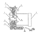
- Fig. 1 shows an example of an embodiment of a device for the recovery of tires, mainly waste tires, in a longitudinal sectional view.
- the tire recovery device comprises a pyrolysis column 1 of a cylindrical shape, preferably, but not necessarily, vertical, provided with a heating means in the form of a tubular inductor 2 which is connected to a high-frequency electric current generator 3.
- the pyrolysis column 1 is provided with a gas outlet 4, as well as with a tire feeding means and a means for discharging pyrolysis solid products.
- the pyrolysis column is also provided with a charging opening 5.
- the tire feeding means comprises a charging hopper 6 and a charging screw 7.
- the means for discharging pyrolysis solid products comprises a discharging screw 8.
- the tire recovery method in accordance with the present invention is carried out using the device for carrying out the same as follows:
- the tires previously reduced are charged into the charging hopper 6 and fed then by the charging screw 7 into the charging window 5 of the pyrolysis column 1.
- the charging screw 7 presses the tire parts to the gas tightness density and pushes them forcedly into the charging window 5 thereby preventing the pyrolysis gases from emitting to the environment, as well as presses air out of the tires being recovered thereby preventing the air from entering the recovery device.
- inductor currents induce an alternating magnetic field within the pyrolysis column 1.
- the frequency of this alternating magnetic field may vary from 1 kHz to 1000 kHz.
- an alternating magnetic field of between 2.0 kHz and 100 kHz in frequency is employed since, for this frequency range, commercialized high-frequency current generators and an element base for them are already available.
- a cyclic remagnetization occurs in the parts of the metal cord, which is a rope twisted of brass-plated steel wires and, as a result, a quick wire heating and a further tire rubber heating take place.
- fine ferromagnetic objects preferably, iron fragments of between 1 cm and 20 cm in size, are charged additionally along with the tires previously divided into parts in which objects, in this case, heat release will occur.
- the pyrolysis fixed residue is cooled with water, intermixed and reduced.
- the metal cord wires are separated finally from the carbonaceous material using, for example, a magnet. Where fine metal objects are used, these are also separated using a magnet and are fed then again to the charging hopper 6.
- a method for the recovery of tires mainly waste tires, which method, owing to both simplicity and versatility thereof, makes it possible to ensure a high capacity of the recovery process.
- the method offers the opportunity to recover tires previously divided into parts. Reduction in power consumption in the recovery process, reduction in expenditure for the implementation of the method of the invention, and a high safety and environmental harmlessness thereof are ensured.
- a device to carry out the method for the recovery of tires, mainly waste tires which device, owing to both simplicity and versatility thereof, also makes it possible to ensure a high capacity of the recovery process with a reduced power consumption and reduced other expenses for operating the device in accordance with the present invention.
Landscapes
- Chemical & Material Sciences (AREA)
- Engineering & Computer Science (AREA)
- Oil, Petroleum & Natural Gas (AREA)
- Materials Engineering (AREA)
- Organic Chemistry (AREA)
- Environmental & Geological Engineering (AREA)
- Mechanical Engineering (AREA)
- Separation, Recovery Or Treatment Of Waste Materials Containing Plastics (AREA)
- Processing Of Solid Wastes (AREA)
- Production Of Liquid Hydrocarbon Mixture For Refining Petroleum (AREA)
- Heating, Cooling, Or Curing Plastics Or The Like In General (AREA)
Applications Claiming Priority (2)
| Application Number | Priority Date | Filing Date | Title |
|---|---|---|---|
| UAA200700722A UA84945C2 (ru) | 2007-01-24 | 2007-01-24 | способ утилизации покрышек и устройство для его осуществления |
| PCT/IB2007/003863 WO2008090405A2 (fr) | 2007-01-24 | 2007-12-11 | Procédé de recyclage de pneus |
Publications (2)
| Publication Number | Publication Date |
|---|---|
| EP2119545A2 true EP2119545A2 (fr) | 2009-11-18 |
| EP2119545A4 EP2119545A4 (fr) | 2011-04-06 |
Family
ID=39644931
Family Applications (1)
| Application Number | Title | Priority Date | Filing Date |
|---|---|---|---|
| EP20070859001 Withdrawn EP2119545A4 (fr) | 2007-01-24 | 2007-12-11 | Procédé de recyclage de pneus |
Country Status (13)
| Country | Link |
|---|---|
| US (1) | US20100087554A1 (fr) |
| EP (1) | EP2119545A4 (fr) |
| JP (1) | JP2010516854A (fr) |
| CN (1) | CN101652233A (fr) |
| AU (1) | AU2007344920A1 (fr) |
| BR (1) | BRPI0720901A2 (fr) |
| CA (1) | CA2676336A1 (fr) |
| EA (1) | EA015476B1 (fr) |
| IL (1) | IL200037A0 (fr) |
| MX (1) | MX2009007906A (fr) |
| UA (1) | UA84945C2 (fr) |
| WO (1) | WO2008090405A2 (fr) |
| ZA (1) | ZA200905433B (fr) |
Cited By (4)
| Publication number | Priority date | Publication date | Assignee | Title |
|---|---|---|---|---|
| CN101813317A (zh) * | 2010-03-27 | 2010-08-25 | 黄广禧 | 低能耗垃圾裂解炉 |
| EP2878388A1 (fr) * | 2013-11-27 | 2015-06-03 | "ELKON" zaklad konstrukcji wdrozen urzadzen elektronicznych i ukladow automatyki | Procédé et dispositif de traitement thermique de fil d'acier mince contaminé, notamment de pneus usés de câble |
| ITUB20160894A1 (it) * | 2016-02-19 | 2017-08-19 | Ferram Recycling S R L | Procedimento per l’ottenimento di materia prima derivante da materiale di scarto |
| EP4013588B1 (fr) * | 2019-09-06 | 2025-01-15 | Tyrecycle A.S. | Méthode de traitement thermique en continu de pneus usés, endommagés ou autrement dégradés, et dispositif pour la mise en oeuvre de cette méthode |
Families Citing this family (8)
| Publication number | Priority date | Publication date | Assignee | Title |
|---|---|---|---|---|
| CN102407233A (zh) * | 2011-11-23 | 2012-04-11 | 珠海新市节能环保科技有限公司 | 超高频涡流加热装置 |
| SG195420A1 (en) * | 2012-06-07 | 2013-12-30 | Ael Enviro Asia Pte Ltd | High energy gas flow tyre pyrolysis using rf inductive plasma in combination with lf induction heating. |
| US8668810B1 (en) | 2013-01-17 | 2014-03-11 | Amass Energy LLC | Device and methods for processing carbon based materials |
| RU2683746C1 (ru) * | 2018-02-14 | 2019-04-01 | Илья Наумович Мирмов | Способ и установка для регенерации резиносодержащих отходов |
| GB2583097B (en) * | 2019-04-15 | 2023-08-16 | Big Atom Ltd | Pyrolysis apparatus and method |
| CN110982541A (zh) * | 2019-05-31 | 2020-04-10 | 北京联合创业环保工程股份有限公司 | 工业有机固废高温热解气化一体化设备 |
| CN112552944B (zh) * | 2020-03-23 | 2022-07-22 | 苏州双福智能科技有限公司 | 一种废旧轮胎热裂解回收用废气处理装置 |
| CN111530894B (zh) * | 2020-05-14 | 2021-01-01 | 江西省天钊色谱科技有限公司 | 一种薄片电子标签回收装置 |
Family Cites Families (13)
| Publication number | Priority date | Publication date | Assignee | Title |
|---|---|---|---|---|
| US4469573A (en) * | 1979-10-22 | 1984-09-04 | Sava Kranj Industrija Gumijevih, Usnjenih In Kemicnih Izdelkov N.L.Sol.O. | Method and arrangement for separating rubber from metal |
| JPS6122613U (ja) * | 1984-07-17 | 1986-02-10 | 昇 山脇 | 廃タイヤのスチ−ルコ−ド分離装置 |
| JPH0753374B2 (ja) * | 1988-02-19 | 1995-06-07 | 富士電機株式会社 | プラスチック廃棄物の減容固化装置 |
| EP0426926A1 (fr) * | 1989-11-07 | 1991-05-15 | Ring Oil Investment N.V. | Procédé, four et installation pour la destruction de déchets industriels |
| JP3405595B2 (ja) * | 1994-05-17 | 2003-05-12 | 住友ゴム工業株式会社 | 金属、ゴム複合体の解体方法 |
| RU2057014C1 (ru) * | 1995-08-08 | 1996-03-27 | Александр Андреевич Набок | Способ разрушения изношенных покрышек и устройство для его осуществления |
| JPH09286990A (ja) * | 1996-04-23 | 1997-11-04 | Yoichi Wada | 廃タイヤの熱分解方法及びその装置 |
| RU2176953C2 (ru) * | 1998-03-17 | 2001-12-20 | Гомельский межотраслевой научно-технический центр "НЕОТЕХ" | Устройство для переработки шин, содержащих металлокорд |
| JP2001252636A (ja) * | 2000-03-10 | 2001-09-18 | Chubu Electric Power Co Inc | 架橋高分子材料の再生方法 |
| JP2002370227A (ja) * | 2001-06-15 | 2002-12-24 | National Institute Of Advanced Industrial & Technology | 誘導加熱によるタイヤ中の金属線除去方法 |
| RU2248881C2 (ru) * | 2003-06-18 | 2005-03-27 | Антоненко Владимир Федорович | Способ термической переработки изношенных шин и резинотехнических изделий |
| RU2269415C2 (ru) * | 2004-04-26 | 2006-02-10 | Криворучко Евгений Петрович | Способ термической переработки изношенных шин и установка для его осуществления |
| UA15001U (en) * | 2005-11-16 | 2006-06-15 | Appliance for utilization of worn tires |
-
2007
- 2007-01-24 UA UAA200700722A patent/UA84945C2/ru unknown
- 2007-12-11 BR BRPI0720901A patent/BRPI0720901A2/pt not_active IP Right Cessation
- 2007-12-11 MX MX2009007906A patent/MX2009007906A/es unknown
- 2007-12-11 EP EP20070859001 patent/EP2119545A4/fr not_active Withdrawn
- 2007-12-11 US US12/524,230 patent/US20100087554A1/en not_active Abandoned
- 2007-12-11 JP JP2009546826A patent/JP2010516854A/ja active Pending
- 2007-12-11 CN CN200780050378A patent/CN101652233A/zh active Pending
- 2007-12-11 WO PCT/IB2007/003863 patent/WO2008090405A2/fr not_active Ceased
- 2007-12-11 EA EA200970699A patent/EA015476B1/ru not_active IP Right Cessation
- 2007-12-11 AU AU2007344920A patent/AU2007344920A1/en not_active Abandoned
- 2007-12-11 CA CA 2676336 patent/CA2676336A1/fr not_active Abandoned
-
2009
- 2009-07-23 IL IL200037A patent/IL200037A0/en unknown
- 2009-08-04 ZA ZA200905433A patent/ZA200905433B/xx unknown
Cited By (6)
| Publication number | Priority date | Publication date | Assignee | Title |
|---|---|---|---|---|
| CN101813317A (zh) * | 2010-03-27 | 2010-08-25 | 黄广禧 | 低能耗垃圾裂解炉 |
| EP2878388A1 (fr) * | 2013-11-27 | 2015-06-03 | "ELKON" zaklad konstrukcji wdrozen urzadzen elektronicznych i ukladow automatyki | Procédé et dispositif de traitement thermique de fil d'acier mince contaminé, notamment de pneus usés de câble |
| ITUB20160894A1 (it) * | 2016-02-19 | 2017-08-19 | Ferram Recycling S R L | Procedimento per l’ottenimento di materia prima derivante da materiale di scarto |
| WO2017141203A1 (fr) * | 2016-02-19 | 2017-08-24 | Solaria S.R.L. | Procédé permettant d'obtenir une matière première provenant de déchets |
| US11105507B2 (en) | 2016-02-19 | 2021-08-31 | Ferram Recycling S.r.l. | Procedure for obtaining raw material resulting from waste material |
| EP4013588B1 (fr) * | 2019-09-06 | 2025-01-15 | Tyrecycle A.S. | Méthode de traitement thermique en continu de pneus usés, endommagés ou autrement dégradés, et dispositif pour la mise en oeuvre de cette méthode |
Also Published As
| Publication number | Publication date |
|---|---|
| EA015476B1 (ru) | 2011-08-30 |
| US20100087554A1 (en) | 2010-04-08 |
| AU2007344920A1 (en) | 2008-07-31 |
| JP2010516854A (ja) | 2010-05-20 |
| IL200037A0 (en) | 2010-04-15 |
| WO2008090405A3 (fr) | 2008-12-04 |
| EA200970699A1 (ru) | 2009-12-30 |
| MX2009007906A (es) | 2009-11-09 |
| UA84945C2 (ru) | 2008-12-10 |
| EP2119545A4 (fr) | 2011-04-06 |
| BRPI0720901A2 (pt) | 2015-11-03 |
| CA2676336A1 (fr) | 2008-07-31 |
| WO2008090405A2 (fr) | 2008-07-31 |
| ZA200905433B (en) | 2010-05-26 |
| CN101652233A (zh) | 2010-02-17 |
Similar Documents
| Publication | Publication Date | Title |
|---|---|---|
| EP2119545A2 (fr) | Procédé de recyclage de pneus | |
| SU1825369A3 (en) | Process for manufacturing form coke and shaft furnace for effecting same | |
| US3794565A (en) | Apparatus for processing heat-decomposable non-gaseous materials | |
| US3649195A (en) | Recovery of electrical energy in carbon black production | |
| US20120043194A1 (en) | Method and apparatus for the energy densification of a material in the form of divided solids, with a view to obtaining pyrolysis oils for energy purposes | |
| EP0075978A2 (fr) | Procédé de récupération des métaux présents dans des déchets de batteries nickel-cadmium | |
| US3377266A (en) | Electrothermal pyrolysis of oil shale | |
| JP2018159477A (ja) | 廃リチウムイオン電池の処理方法 | |
| US20160075953A1 (en) | Oil shale retorting | |
| CN103666507A (zh) | 一种内热式煤干馏炉、内热式煤干馏系统及煤干馏工艺方法 | |
| US20050234274A1 (en) | Method and installation for low-temperature pyrolysis of rubber products, steel/rubber composites, and use of the pyrolysis products | |
| Jacob et al. | Novel design of a rotary calciner internally heated with electrical axial heaters: Experiments and modelling | |
| KR101352017B1 (ko) | 폐전선의 동선 회수장치 및 방법 | |
| EP0353541A2 (fr) | Procédé de recyclage de pneus à ceinture d'acier | |
| CN220116400U (zh) | 一种含油污泥处理装置 | |
| CN105084323A (zh) | 一种利用硫铁矿制造硫磺和氧化铁的系统与方法 | |
| US8945351B2 (en) | Induction heated gasifier | |
| EP2524956B1 (fr) | Procédé de traitement thermique de pneumatiques usagés | |
| JP4440696B2 (ja) | 下水汚泥の炭化方法 | |
| JP2011056504A (ja) | Pcb含有物の処理方法及びpcb含有物の処理装置 | |
| KR20170038827A (ko) | 폐타이어 또는 재생불가 타이어를 지속적으로 열처리하기 위한 장치 | |
| CN111171854A (zh) | 一种轮胎物料连续性红外裂解设备及工艺方法 | |
| JPS5823883A (ja) | 廃タイヤの乾溜方法及装置 | |
| US5414205A (en) | Method for treating soil contaminated with hydrocarbons | |
| DE102005063160B4 (de) | Verfahren und Einrichtung zur Entsorgung und sowohl energetischen als auch stofflichen Nutzung von Abfällen mit Komponenten von vulkanisiertem Kautschuk und Polymer |
Legal Events
| Date | Code | Title | Description |
|---|---|---|---|
| PUAI | Public reference made under article 153(3) epc to a published international application that has entered the european phase |
Free format text: ORIGINAL CODE: 0009012 |
|
| 17P | Request for examination filed |
Effective date: 20090812 |
|
| AK | Designated contracting states |
Kind code of ref document: A2 Designated state(s): AT BE BG CH CY CZ DE DK EE ES FI FR GB GR HU IE IS IT LI LT LU LV MC MT NL PL PT RO SE SI SK TR |
|
| DAX | Request for extension of the european patent (deleted) | ||
| A4 | Supplementary search report drawn up and despatched |
Effective date: 20110308 |
|
| RIC1 | Information provided on ipc code assigned before grant |
Ipc: B29B 17/02 20060101ALI20110302BHEP Ipc: B29B 17/00 20060101AFI20090903BHEP Ipc: F23G 5/027 20060101ALI20110302BHEP Ipc: B29C 35/08 20060101ALI20110302BHEP Ipc: F23G 5/033 20060101ALI20110302BHEP |
|
| STAA | Information on the status of an ep patent application or granted ep patent |
Free format text: STATUS: THE APPLICATION IS DEEMED TO BE WITHDRAWN |
|
| 18D | Application deemed to be withdrawn |
Effective date: 20111005 |