EP2119558A1 - Procédé de production d'un sachet à bec verseur - Google Patents
Procédé de production d'un sachet à bec verseur Download PDFInfo
- Publication number
- EP2119558A1 EP2119558A1 EP07706309A EP07706309A EP2119558A1 EP 2119558 A1 EP2119558 A1 EP 2119558A1 EP 07706309 A EP07706309 A EP 07706309A EP 07706309 A EP07706309 A EP 07706309A EP 2119558 A1 EP2119558 A1 EP 2119558A1
- Authority
- EP
- European Patent Office
- Prior art keywords
- pouch
- package
- package material
- body section
- heat
- Prior art date
- Legal status (The legal status is an assumption and is not a legal conclusion. Google has not performed a legal analysis and makes no representation as to the accuracy of the status listed.)
- Granted
Links
Images





Classifications
-
- B—PERFORMING OPERATIONS; TRANSPORTING
- B31—MAKING ARTICLES OF PAPER, CARDBOARD OR MATERIAL WORKED IN A MANNER ANALOGOUS TO PAPER; WORKING PAPER, CARDBOARD OR MATERIAL WORKED IN A MANNER ANALOGOUS TO PAPER
- B31B—MAKING CONTAINERS OF PAPER, CARDBOARD OR MATERIAL WORKED IN A MANNER ANALOGOUS TO PAPER
- B31B70/00—Making flexible containers, e.g. envelopes or bags
- B31B70/74—Auxiliary operations
- B31B70/81—Forming or attaching accessories, e.g. opening devices, closures or tear strings
- B31B70/84—Forming or attaching means for filling or dispensing contents, e.g. valves or spouts
- B31B70/844—Applying rigid valves, spouts, or filling tubes
-
- B—PERFORMING OPERATIONS; TRANSPORTING
- B31—MAKING ARTICLES OF PAPER, CARDBOARD OR MATERIAL WORKED IN A MANNER ANALOGOUS TO PAPER; WORKING PAPER, CARDBOARD OR MATERIAL WORKED IN A MANNER ANALOGOUS TO PAPER
- B31B—MAKING CONTAINERS OF PAPER, CARDBOARD OR MATERIAL WORKED IN A MANNER ANALOGOUS TO PAPER
- B31B2155/00—Flexible containers made from webs
-
- B—PERFORMING OPERATIONS; TRANSPORTING
- B31—MAKING ARTICLES OF PAPER, CARDBOARD OR MATERIAL WORKED IN A MANNER ANALOGOUS TO PAPER; WORKING PAPER, CARDBOARD OR MATERIAL WORKED IN A MANNER ANALOGOUS TO PAPER
- B31B—MAKING CONTAINERS OF PAPER, CARDBOARD OR MATERIAL WORKED IN A MANNER ANALOGOUS TO PAPER
- B31B2155/00—Flexible containers made from webs
- B31B2155/001—Flexible containers made from webs by folding webs longitudinally
- B31B2155/0014—Flexible containers made from webs by folding webs longitudinally having their openings facing transversally to the direction of movement
-
- B—PERFORMING OPERATIONS; TRANSPORTING
- B31—MAKING ARTICLES OF PAPER, CARDBOARD OR MATERIAL WORKED IN A MANNER ANALOGOUS TO PAPER; WORKING PAPER, CARDBOARD OR MATERIAL WORKED IN A MANNER ANALOGOUS TO PAPER
- B31B—MAKING CONTAINERS OF PAPER, CARDBOARD OR MATERIAL WORKED IN A MANNER ANALOGOUS TO PAPER
- B31B2155/00—Flexible containers made from webs
- B31B2155/002—Flexible containers made from webs by joining superimposed webs, e.g. with separate bottom webs
-
- B—PERFORMING OPERATIONS; TRANSPORTING
- B31—MAKING ARTICLES OF PAPER, CARDBOARD OR MATERIAL WORKED IN A MANNER ANALOGOUS TO PAPER; WORKING PAPER, CARDBOARD OR MATERIAL WORKED IN A MANNER ANALOGOUS TO PAPER
- B31B—MAKING CONTAINERS OF PAPER, CARDBOARD OR MATERIAL WORKED IN A MANNER ANALOGOUS TO PAPER
- B31B2160/00—Shape of flexible containers
- B31B2160/20—Shape of flexible containers with structural provision for thickness of contents
-
- B—PERFORMING OPERATIONS; TRANSPORTING
- B31—MAKING ARTICLES OF PAPER, CARDBOARD OR MATERIAL WORKED IN A MANNER ANALOGOUS TO PAPER; WORKING PAPER, CARDBOARD OR MATERIAL WORKED IN A MANNER ANALOGOUS TO PAPER
- B31B—MAKING CONTAINERS OF PAPER, CARDBOARD OR MATERIAL WORKED IN A MANNER ANALOGOUS TO PAPER
- B31B2170/00—Construction of flexible containers
-
- B—PERFORMING OPERATIONS; TRANSPORTING
- B31—MAKING ARTICLES OF PAPER, CARDBOARD OR MATERIAL WORKED IN A MANNER ANALOGOUS TO PAPER; WORKING PAPER, CARDBOARD OR MATERIAL WORKED IN A MANNER ANALOGOUS TO PAPER
- B31B—MAKING CONTAINERS OF PAPER, CARDBOARD OR MATERIAL WORKED IN A MANNER ANALOGOUS TO PAPER
- B31B70/00—Making flexible containers, e.g. envelopes or bags
- B31B70/14—Cutting, e.g. perforating, punching, slitting or trimming
- B31B70/16—Cutting webs
- B31B70/18—Cutting webs longitudinally
-
- B—PERFORMING OPERATIONS; TRANSPORTING
- B31—MAKING ARTICLES OF PAPER, CARDBOARD OR MATERIAL WORKED IN A MANNER ANALOGOUS TO PAPER; WORKING PAPER, CARDBOARD OR MATERIAL WORKED IN A MANNER ANALOGOUS TO PAPER
- B31B—MAKING CONTAINERS OF PAPER, CARDBOARD OR MATERIAL WORKED IN A MANNER ANALOGOUS TO PAPER
- B31B70/00—Making flexible containers, e.g. envelopes or bags
- B31B70/26—Folding sheets, blanks or webs
- B31B70/262—Folding sheets, blanks or webs involving longitudinally folding, i.e. along a line parallel to the direction of movement
- B31B70/266—Folding sheets, blanks or webs involving longitudinally folding, i.e. along a line parallel to the direction of movement involving gusset-forming
Definitions
- the present invention relates to a method for manufacturing a spouted pouch package including a bottom gusset stand-up pouch and a spout attached to the pouch.
- the spouted pouch package SP includes a pouch P and a spout S.
- the pouch P includes a body section P1 which is heat-sealed at side edges thereof by a predetermined width, a top gusset section P2 provided on a top end portion of the body section P1, and a bottom gusset section P3 provided on a bottom end portion of the body section P1.
- the spout S is attached to the top gusset section P2 of the pouch P.
- the shaded portions show the heat-sealed portions.
- the side edges of the top end portion of the body section P1 and the side edges of the bottom end portion of the body section P1 are not heat-sealed to each other. Instead, the peripheral edge of the top end portion of the body section P1 is bent so as to expand outward, and a peripheral edge portion of a top gusset sheet which forms the top gusset section P2 is heat-sealed to the top end portion of the body section P1 at the peripheral edge thereof.
- a peripheral edge portion of a bottom gusset sheet which forms the bottom gusset section P3 is heat-sealed to the bottom end portion of the body section P1 at the peripheral edge thereof such that the bottom gusset sheet is folded inward from the bottom side of the body section P1.
- the bottom gusset sheet has cut portions c at each side edge thereof, and the cut portions c at each side edge meet each other, as shown in Fig. 13(b) , when the bottom gusset sheet is folded in half.
- the side edges of the bottom end portion of the body section P1 are partially heat-sealed to each other through the cut portions c.
- the spout S includes a main body S1 and a flange portion S2 having a large diameter at the bottom end of the main body S1.
- the spout S is attached to the top gusset section P2 by inserting the main body S1 through an attachment hole formed in the top gusset section P2 from below and fixing the flange portion S2 to a portion of the top gusset section P2 around the attachment hole.
- Patent Document 1 Japanese Utility Model Registration No. 2605636
- the spouted pouch package SP includes the pouch P having the top gusset section P2, as described above, and the shape of the spouted pouch package SP is close to that of, for example, a bottle container. Therefore, compared to a common bottom gusset spouted pouch package which does not have the top gusset section, the spouted pouch package SP is advantageous in that sufficient capacity can be provided without increasing the width or height of the pouch.
- the spout S is not attached to the pouch P at a heat-sealed edge thereof, but is attached to the top gusset section P1 at a central area thereof. Therefore, unlike a common spouted pouch package in which the spout is attached to the pouch at a heat-sealed edge thereof, it is not possible to use a method of heat-sealing the pouch while the spout is sandwiched at the heat-sealing edge of the pouch. Thus, there is a problem that the spouted pouch package SP cannot be efficiently mass-produced.
- an object of the present invention is to provide a method for efficiently manufacturing a spouted pouch package including a spout attached to a top gusset section from a single sheet of package material by mass production.
- the invention of claim 1 provides a method for manufacturing a spouted pouch package including a pouch and a spout, the pouch including a body section which is heat-sealed by a predetermined width at both sides edges thereof, a top gusset section provided on a top end portion of the body section, and a bottom gusset section provided on a bottom end portion of the body section, the spout being attached to the top gusset section of the pouch.
- the method includes a step of folding long package material while conveying the package material, the package material being folded in a width direction of the package material such that a conveying direction in which the package material is conveyed is aligned with a width direction of the pouch; a step of attaching the spout to a portion of the folded package material which corresponds to the top gusset section; a step of heat-sealing a portion corresponding to a peripheral edge of the top gusset section and a portion corresponding to a top edge of the body section to each other by a predetermined width; a step of heat-sealing portions corresponding to side edges of the body section to each other by a predetermined width and heat-sealing a portion corresponding to a peripheral edge of the bottom gusset section and a portion corresponding to a peripheral edge of the bottom end portion of the body section to each other by a predetermined width; and a step of cutting the heat-sealed portions formed at the portions corresponding to the side edges
- the package material is folded such that a side portion of the package material in the width direction of the package material forms a part of the peripheral edge of the top gusset section in the pouch.
- the portion of the package material corresponding to the top gusset section and a portion of the package material corresponding to the body section are heat-sealed by being clamped together between sealing bars while a portion of the body section which corresponds to the top end portion at one side of the body section and which is heat-sealed to the peripheral edge of the top gusset section is folded downward.
- the manufacturing method according to claim 1 or 2 further includes a step of locally heat-sealing portions corresponding to boundaries between the top edge and the side edges of the body section by clamping the portion of the package material corresponding to the top gusset section and a portion of the package material corresponding to the body section together between sealing bars while a portion of the body section which corresponds to the top end portion at one side of the body section and which is heat-sealed to the peripheral edge of the top gusset section is folded downward, the step being performed after the portions corresponding to the side edges of the body section are heat-sealed to each other by the predetermined width and before the spouted pouch package is released by cutting the heat-sealed portions.
- the bottom gusset spouted pouch package having the spout attached to the top gusset section can be efficiently mass-produced from a single sheet of package material.
- the top gusset section is often formed in a hexagonal shape, and a cutting mechanism for cutting the top gusset section is generally provided. Therefore, as in the method for manufacturing the spouted pouch package according to claim 2, the package material may be folded such that one of the side portions of the package material in the width direction of the package material forms a part of the peripheral edge of the top gusset section in the pouch. In such a case, the side portions of the package material in the width direction of the package material are bonded finally at the top gusset section. Therefore, the redundant portions at the side portions of the package material in the width direction of the package material may be cut when the top gusset section is cut in a predetermined shape. Thus, it is not necessary to use a dedicated cutter.
- the portion of the package material corresponding to the top gusset section and the portion of the package material corresponding to the body section are heat-sealed by being clamped together between the sealing bars. Therefore, the boundaries between the top edge and the side edges of the body section, where sealing failure easily occurs, can be reliably heat-sealed and the sealing performance can be improved.
- the portions corresponding to the side edges of the body section are heat-sealed to each other by the predetermined width
- the portions corresponding to the boundaries between the top edge and the side edges of the body section are locally heat-sealed by clamping the portion of the package material corresponding to the top gusset section and the portion of the package material corresponding to the body section together between the sealing bars. Therefore, similar to the method for manufacturing the spouted pouch package according to claim 3, the boundaries between the top edge and the side edges of the body section, where sealing failure easily occurs, can be reliably heat-sealed and the sealing performance can be improved.
- Fig. 1 is a schematic diagram illustrating a pouch-package manufacturing apparatus for manufacturing a spouted pouch package SP shown in Figs. 12 and 13 in which a spout S is attached to a pouch P.
- the pouch-package manufacturing apparatus 1 spouted pouch packages SP are manufactured from a long band-shaped package material M, and both sides of the package material M in the width direction of the package material across a center line are used.
- the pouch-package manufacturing apparatus 1 includes a package-material conveying unit 11, a score-line forming unit 12, a hole-forming unit 13, a folding unit 14, a spout-attaching unit 15, a first sealing unit 16, a first cutting unit 17, a second sealing unit 18, and a second cutting unit 19.
- the long band-shaped package material M which is formed of a synthetic resin sheet, is pulled out from a package-material roll R obtained by winding the package material M in a roll-like shape, and is conveyed to the score-line forming unit 12.
- the score-line forming unit 12 forms score lines on the package material M.
- the hole-forming unit 13 forms spout attachment holes in areas corresponding to top gusset sections P2 of pouches P in the package material M on which the score lines are formed.
- the hole-forming unit 13 also forms cut-portion forming holes for forming cut portions c (see Fig. 13(b) ) in areas corresponding to bottom gusset sections P3 of the pouches P.
- the folding unit 14 folds the package material M in the width direction of the package material so that a conveying direction in which the package material M is conveyed is aligned with the width direction of the pouches P.
- the spout-attaching unit 15 attaches spouts S to the spout attachment holes H formed in the areas corresponding to the top gusset sections P2 in the package material M in the folded state.
- the first sealing unit 16 heat-seals a portion corresponding to the peripheral edge of the top gusset section P2 of each pouch P and a portion corresponding to the top edge of a body section P1 of each pouch P to each other by a predetermined width.
- the first cutting unit 17 cuts the package material M in the width direction of the package material.
- the second sealing unit 18 heat-seals portions corresponding to side edges of the body section P1 of each pouch P to each other by a predetermined width, and also heat-seals a portion corresponding to the peripheral edge of the bottom gusset section P3 of each pouch P and a portion corresponding to the peripheral edge of a bottom end portion of the body section P1 of each pouch P to each other by a predetermined width.
- the second cutting unit 19 cuts heat-sealed portions having a predetermined width formed at the portions corresponding to the side edges of the body section P1 of each pouch P, so that the spouted pouch packages SP are separated from each other.
- a continuous conveying unit 21 which continuously conveys the folded package material M is disposed between the folding unit 14 and the spout-attaching unit 15.
- an intermittent conveying unit 22 which intermittently conveys the package material M is disposed between the second sealing unit 18 and the second cutting unit 19.
- An accumulator section 23 is disposed between the continuous conveying unit 21 and the spout-attaching unit 15 and accumulates the folded package material conveyed by the continuous conveying unit 21 while the intermittent conveying unit 22 is in the stopped state.
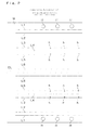
- the score-line forming unit 12 forms a plurality of score lines L1 to L6, as shown in Fig. 2 .
- the spout attachment holes H and the cut-portion forming holes h are successively formed by the hole-forming unit 13, as shown in Fig. 2 .
- the score lines L1 to L6, the spout attachment holes H, and the cut-portion forming holes h are formed symmetrically about the center line CL of the package material M.
- the package material M on which the score lines L1 to L6 are formed and in which the spout attachment holes H and the cut-portion forming holes h are formed is conveyed to the folding unit 14, which folds the package material M in the width direction. As shown in Fig. 3 , the package material M is folded along the score lines L1 to L6 such that portions corresponding to the body section P1, the top gusset section P2, and the bottom gusset section P3 are formed for each pouch P.
- a portion corresponding to the peripheral edge of the top gusset section P2 of each pouch P and a portion corresponding to the top edge of the body section P1 of each pouch P are clamped between sealing members 16a, 16a, and are thereby heat-sealed to each other by a predetermined width in a substantially octagonal shape. Then, the heat-sealed portions are cooled. Then, as shown in Fig. 8 , unnecessary portions are cut off so that the portions corresponding to the top gusset sections P2 have a substantially octagonal shape. In Figs. 7(b) and 8 , the shaded portions show the heat-sealed portions.
- the package material M is cut along the center line CL by the first cutting unit 17.
- the package material M is folded such that the portions corresponding to the top gusset sections P2 to which the spouts S are attached stand upright.
- portions including the folded portions are clamped between sealing members 18a, 18a, so that portions corresponding to side edges of the body section P1 of each pouch P are heat-sealed to each other by a predetermined width, as shown in Fig.
- the second cutting unit 19 cuts the heat-sealed portions having the predetermined width at the portions corresponding to the side edges of the body section P1 of each pouch P.
- the heat-sealed portions are cut along the dot-dash lines shown in Fig. 11 . Accordingly, as shown in Fig. 12 , each spouted pouch package SP is obtained in the state in which the pouch P is folded such that the top gusset section P2 faces the front. In Fig. 12 , the shaded portions show the heat-sealed portions.
- the bottom gusset spouted pouch package SP having the spout S attached to the top gusset section P2 can be efficiently mass-produced from a single sheet of package material M.
- the second sealing unit 18 when the portions corresponding to side edges of the body section P1 of each pouch P are heat-sealed to each other by a predetermined width, a portion corresponding to a top end portion of the body section P1 is folded such that the portion corresponding to the top gusset section P2 to which the spout S is attached stands upright. Then, the portion including the folded portion is clamped between the sealing bars. Therefore, the boundaries between the top edge and the side edges of the body section P1, where sealing failure easily occurs, can be reliably heat-sealed.
- the distance between each of the side edges of the package material M and the score line L1 adjacent thereto and the distance between the score lines L6, L6 are regularly set so that the side edges of the package material M meet each other on the center line CL when the package material M is folded.
- the folding positions will be displaced in the manufacturing process. In such a case, the displacement will accumulate and the side edges of the package material M in the width direction of the package material will eventually be largely displaced from each other instead of meeting with each other. Therefore, as shown in Figs. 15(a) and 15(b) , preferably, an allowance is provided in the distance between each of the side edges of the package material M and the score line L1 adjacent thereto and the distance between the score lines L6, L6, and redundant portions are cut off.
- the redundant portions can be cut off in the process of cutting the package material M in the width direction with the first cutting unit 17. Therefore, it is not necessary to use a dedicated cutter.
- the second cutting unit 19 separates the spouted pouch packages SP from each other immediately after the portions corresponding to the side edges of the body section P1 of each pouch P are heat-sealed to each other and the portion corresponding to the peripheral edge of the bottom gusset section P3 of each pouch P and the portion corresponding to the peripheral edge of the bottom end portion of the body section P1 of each pouch P are heat-sealed to each other by the second sealing unit 18.
- a third sealing unit in which only the portion corresponding to the top end portion of the body section P1 which is folded is clamped by sealing bars again and is locally heat-sealed may be provided between the second sealing unit 18 and the second cutting unit 19. In such a case, the boundaries between the top edge and the side edges of the body section P1, where sealing failure easily occurs, can be more reliably heat-sealed.
- the first cutting unit 17 which cuts the package material M in the width direction of the package material is disposed between the first sealing unit 16 and the second sealing unit 18.
- the present invention is not limited to this, and the first cutting unit 17 may also be disposed between the score-line forming unit 12 and the hole-forming unit 13, as in a pouch-package manufacturing apparatus 1A shown in Fig. 16 .
- pairs of folding units 14, spout-attaching units 15, first sealing units 16, second sealing units 18, second cutting units 19, continuous conveying units 21, intermittent conveying units 22, and accumulator sections 23 must be provided.
- the package material M is folded such that the side edges of the package material M meet each other on the center line CL.
- portions corresponding to the top gusset sections P2 of the pouches P are positioned at the side edges of the package material M.
- the present invention is not limited to this.
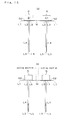
- portions corresponding to the top gusset sections P2 of the pouches P may be disposed at one side of the package material M, and the package material M may be folded by the folding unit 14 as shown in Fig. 18(a) .
- the spout-attaching unit 15 positions the side portion of the package material M as shown in Fig. 18(b) , and then attaches two spouts S to the side portion. Then, the portion corresponding to the top gusset sections P2 to which the spouts S are attached is folded as shown in Fig. 18(c) .
- the sealing performance at the boundaries between the top edge and the side edges of the body section P1 of each pouch P, where sealing failure easily occurs is increased by the following method. That is, in the second sealing unit 18, when the portions corresponding to the side edges of the body section P1 of each pouch P are heat-sealed to each other by a predetermined width, the portion corresponding to the top end portion of the body section P1 is folded such that the portion corresponding to the top gusset section P2 to which the spout S is attached stands upright. Then, the portion including the folded portion is clamped between the sealing members 18a.
- the present invention is not limited to this, and the sealing performance at the boundaries between the top edge and the side edges of the body section P1 of each pouch P, where sealing failure easily occurs, may also be increased by the following method. That is, first, only the portions corresponding to the side edges of the body section P1 of each pouch P are heat-sealed to each other by a predetermined width. Then, before the package material M is cut by the second cutting unit 19, the portion corresponding to the top end portion of the body section P1 is folded such that the portion corresponding to the top gusset section P2 to which the spout S is attached stands upright. Then, only the folded portion is clamped between sealing bars again and be locally heat-sealed.
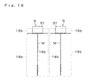
- the first sealing step and the second sealing step may be simultaneously performed. More specifically, the sealing members 16b, 18b may be used to clamp the portion corresponding to the peripheral edge of the top gusset section P2 of each pouch P and the portion corresponding to the top edge of the body section P1 of each pouch P, to clamp the portions corresponding to the side edges of the body section P1 of each pouch P, and to clamp the portion corresponding to the peripheral edge of the bottom gusset section P3 of each pouch P and the portion corresponding to the peripheral edge of the bottom end portion of the body section P1 of each pouch P.
- two spouted pouch packages SP are simultaneously manufactured from a single sheet of package material M.
- the present invention is not limited to this, and may, of course, also be applied to the case in which three or more spouted pouch packages SP are simultaneously manufactured or the case in which the single spouted pouch packages SP are manufactured one at a time from a single package material M.
- the present invention can be applied to the case where a bottom gusset spouted pouch package in which a spout is attached to a top gusset section is mass-produced.
Landscapes
- Making Paper Articles (AREA)
Priority Applications (1)
| Application Number | Priority Date | Filing Date | Title |
|---|---|---|---|
| PL07706309T PL2119558T3 (pl) | 2007-02-07 | 2007-02-07 | Sposób wytwarzania workowego pojemnika z dziobkiem |
Applications Claiming Priority (1)
| Application Number | Priority Date | Filing Date | Title |
|---|---|---|---|
| PCT/JP2007/000061 WO2008096392A1 (fr) | 2007-02-07 | 2007-02-07 | Procédé de production d'un sachet à bec verseur |
Publications (4)
| Publication Number | Publication Date |
|---|---|
| EP2119558A1 true EP2119558A1 (fr) | 2009-11-18 |
| EP2119558A4 EP2119558A4 (fr) | 2014-05-28 |
| EP2119558B1 EP2119558B1 (fr) | 2019-05-08 |
| EP2119558B8 EP2119558B8 (fr) | 2019-06-12 |
Family
ID=39681313
Family Applications (1)
| Application Number | Title | Priority Date | Filing Date |
|---|---|---|---|
| EP07706309.7A Active EP2119558B8 (fr) | 2007-02-07 | 2007-02-07 | Procédé de production d'un sachet à bec verseur |
Country Status (6)
| Country | Link |
|---|---|
| US (1) | US9636883B2 (fr) |
| EP (1) | EP2119558B8 (fr) |
| JP (1) | JP5179386B2 (fr) |
| ES (1) | ES2729842T3 (fr) |
| PL (1) | PL2119558T3 (fr) |
| WO (1) | WO2008096392A1 (fr) |
Cited By (2)
| Publication number | Priority date | Publication date | Assignee | Title |
|---|---|---|---|---|
| ES2384067A1 (es) * | 2009-08-04 | 2012-06-29 | Volpak, S.A.U. | Procedimiento y máquina para fabricar en continuo envases de material flexible. |
| EP4140720A4 (fr) * | 2020-04-23 | 2024-06-26 | Fuji Seal International, Inc. | Procédé de fabrication d'un emballage pour contenant de type sachet, et dispositif de fabrication d'un emballage pour contenant de type sachet |
Families Citing this family (16)
| Publication number | Priority date | Publication date | Assignee | Title |
|---|---|---|---|---|
| USD604637S1 (en) | 2008-10-31 | 2009-11-24 | Fuji Seal International, Inc. | Packaging bag |
| USD610918S1 (en) | 2008-10-31 | 2010-03-02 | Fuji Seal International, Inc. | Packaging bag |
| USD627237S1 (en) | 2009-02-19 | 2010-11-16 | Fuji Seal International, Inc. | Packaging bag |
| ES2368410B1 (es) * | 2010-02-04 | 2012-09-24 | Volpak, S.A.U. | Envase tipo saquito de material flexible. |
| JP5465057B2 (ja) * | 2010-03-30 | 2014-04-09 | 株式会社フジシールインターナショナル | 製袋機の角部切断装置 |
| JP6025338B2 (ja) * | 2012-02-08 | 2016-11-16 | 株式会社フジシールインターナショナル | 製袋機 |
| WO2014054760A1 (fr) | 2012-10-03 | 2014-04-10 | 日本山村硝子株式会社 | Réceptacle sous forme de poche |
| JP6161362B2 (ja) * | 2013-03-29 | 2017-07-12 | 株式会社フジシールインターナショナル | スパウト付きパウチ容器の製造方法、および、スパウト付きパウチ容器 |
| JP6121774B2 (ja) * | 2013-03-29 | 2017-04-26 | 株式会社フジシールインターナショナル | スパウト付きパウチ容器の製造方法、および、スパウト付きパウチ容器 |
| NL2013495B1 (en) * | 2014-09-18 | 2016-09-29 | Sluis Cigar Machinery Bv | Pouch maker for making block-bottom tobacco pouches. |
| JP5913695B1 (ja) * | 2015-07-06 | 2016-04-27 | トタニ技研工業株式会社 | スパウト装着装置 |
| WO2017033628A1 (fr) | 2015-08-24 | 2017-03-02 | 株式会社フジシールインターナショナル | Structure alignée de récipients sous forme de sachet, ses dispositif et procédé de fabrication |
| WO2017058138A1 (fr) * | 2015-09-28 | 2017-04-06 | Bemis Company, Inc. | Poche comprenant une soupape de distribution souple auto-scellante |
| JP6270956B1 (ja) * | 2016-10-17 | 2018-01-31 | 有限会社エル・エス・エム | プラスチック包装袋の折りたたみ癖付け方法とその装置 |
| US20200017268A1 (en) * | 2018-07-12 | 2020-01-16 | Lu-Wen Chang | Soft package with strengthened hot pressing traces and manufacturing method thereof |
| NL2022317B1 (en) * | 2018-12-27 | 2020-07-23 | Fuji Seal Int Inc | Method and appratus for manufacturing spouted pouch containers |
Family Cites Families (23)
| Publication number | Priority date | Publication date | Assignee | Title |
|---|---|---|---|---|
| US3200557A (en) * | 1961-09-25 | 1965-08-17 | Int Paper Co | Method and apparatus for sealing milk containers and the like |
| US3486423A (en) * | 1966-06-03 | 1969-12-30 | Illinois Creamery Supply Co | Machine for automatically forming,filling,closing and sealing plastic coated gable top cartons of paperboard or the like |
| JPS5843022B2 (ja) * | 1980-10-21 | 1983-09-24 | 本州製紙株式会社 | 内袋入包装箱の製造装置 |
| US4470152A (en) * | 1982-06-14 | 1984-09-04 | Basic Packaging Systems, Inc. | Valve bag with alignment means |
| WO1986006344A1 (fr) * | 1985-04-22 | 1986-11-06 | Inpaco, Inc. | Methodes de fixation d'accessoires dans des machines horizontales de formage/remplissage/fermeture |
| DE3336269A1 (de) * | 1983-10-05 | 1985-04-18 | Carl Edelmann Gmbh, 7920 Heidenheim | Innenbeutelpackung mit verschliessbarem ausgiessstutzen |
| US4816104A (en) * | 1984-05-02 | 1989-03-28 | Mobil Oil Corporation | Methods and systems for preparing flat-bottom thermoplastic sack |
| US4946431A (en) * | 1986-06-30 | 1990-08-07 | Katana Corporation | Apparatus for the manufacture of block-sealed side-gussetted bags |
| US4685148A (en) * | 1986-09-08 | 1987-08-04 | Basic Packaging Systems, Inc. | Square ended valve bag |
| DE3712717A1 (de) * | 1987-04-14 | 1988-11-03 | Schmermund Maschf Alfred | Bodenfaltungspacker |
| US4790803A (en) * | 1987-06-30 | 1988-12-13 | T. C. Manufacturing Company, Inc. | Method of making bottom gusset bag pad arrangement for liquid containers |
| DE4015119A1 (de) * | 1989-07-10 | 1991-01-31 | Pkl Verpackungssysteme Gmbh | Quaderfoermige giebelpackung mit im bereich des flachdachs angebrachtem ausgiesser |
| GB8920336D0 (en) * | 1989-09-08 | 1989-10-25 | Reed Packaging Ltd | Carton and blank for making the same |
| AR245418A1 (es) * | 1990-03-02 | 1994-01-31 | Emzo S A I C | Mejoras en bolsas laminares flexibles, con pico de descarga y una maquina para obtener dicha bolsa en forma masiva. |
| US5254073A (en) * | 1990-04-27 | 1993-10-19 | Kapak Corporation | Method of making a vented pouch |
| DE9109759U1 (de) * | 1991-08-07 | 1991-11-21 | Europa Carton Ag, 2000 Hamburg | Flüssigkeitspackung |
| ATE125224T1 (de) * | 1992-02-28 | 1995-08-15 | Louis Doyen | Biegsamer behälter, verfahren und vorrichtung zu seiner herstellung. |
| JP2605636B2 (ja) | 1994-10-17 | 1997-04-30 | 日本電気株式会社 | 光ヘッドの非点隔差補正方法および装置 |
| JPH0930506A (ja) * | 1995-07-18 | 1997-02-04 | Aipurasu Kk | 自動製袋計量充填包装方法 |
| US5810706A (en) * | 1995-08-31 | 1998-09-22 | W. R. Grace & Co.-Conn. | bag with an access hole in one panel |
| JP3944976B2 (ja) * | 1997-10-31 | 2007-07-18 | 東洋製罐株式会社 | 折込部を有する密封袋及びその製造方法 |
| JP2003534988A (ja) * | 2000-05-30 | 2003-11-25 | アムコー・パッケージング・(ニュー・ジーランド)・リミテッド | プラスチックパッケージング |
| US7204641B2 (en) * | 2002-09-19 | 2007-04-17 | Illinois Tool Works Inc. | Pouch with spout |
-
2007
- 2007-02-07 WO PCT/JP2007/000061 patent/WO2008096392A1/fr not_active Ceased
- 2007-02-07 EP EP07706309.7A patent/EP2119558B8/fr active Active
- 2007-02-07 PL PL07706309T patent/PL2119558T3/pl unknown
- 2007-02-07 JP JP2008556919A patent/JP5179386B2/ja active Active
- 2007-02-07 ES ES07706309T patent/ES2729842T3/es active Active
-
2009
- 2009-08-07 US US12/537,583 patent/US9636883B2/en active Active
Cited By (2)
| Publication number | Priority date | Publication date | Assignee | Title |
|---|---|---|---|---|
| ES2384067A1 (es) * | 2009-08-04 | 2012-06-29 | Volpak, S.A.U. | Procedimiento y máquina para fabricar en continuo envases de material flexible. |
| EP4140720A4 (fr) * | 2020-04-23 | 2024-06-26 | Fuji Seal International, Inc. | Procédé de fabrication d'un emballage pour contenant de type sachet, et dispositif de fabrication d'un emballage pour contenant de type sachet |
Also Published As
| Publication number | Publication date |
|---|---|
| EP2119558B8 (fr) | 2019-06-12 |
| EP2119558B1 (fr) | 2019-05-08 |
| US20100022374A1 (en) | 2010-01-28 |
| ES2729842T3 (es) | 2019-11-06 |
| JP5179386B2 (ja) | 2013-04-10 |
| JPWO2008096392A1 (ja) | 2010-05-20 |
| US9636883B2 (en) | 2017-05-02 |
| EP2119558A4 (fr) | 2014-05-28 |
| WO2008096392A1 (fr) | 2008-08-14 |
| PL2119558T3 (pl) | 2019-10-31 |
Similar Documents
| Publication | Publication Date | Title |
|---|---|---|
| EP2119558A1 (fr) | Procédé de production d'un sachet à bec verseur | |
| US12472718B2 (en) | Zipper tape-equipped bag body, article housing method for zipper tape-equipped bag body, manufacturing method for zipper tape-equipped bag body, and manufacturing device for zipper tape-equipped bag body | |
| US4181069A (en) | Method for producing double streams of side-welded bags in heat-welded pad form | |
| AU2002349910B2 (en) | Reclosable package and method for manufacturing the same | |
| AU2002305062B2 (en) | Gusseted packages | |
| US20050069227A1 (en) | Flexible package having integrated slit member | |
| US8122687B2 (en) | Method of making flexible packages having slide closures | |
| EP3395560B1 (fr) | Machine de fabrication de poches | |
| EP2489284A1 (fr) | Fermeture éclair, sac d'emballage avec fermeture éclair, procédé de fabrication d'un sac d'emballage avec fermeture éclair et son dispositif de fabrication | |
| AU2002349910A1 (en) | Reclosable package and method for manufacturing the same | |
| CA2425664A1 (fr) | Remplissage et utilisation de sacs refermables | |
| CN102648133A (zh) | 带有塑料可重新关闭的顶盖的纸板箱 | |
| US6527445B2 (en) | Liners or bags and method of making them | |
| JP6280612B2 (ja) | 製袋機 | |
| US11999532B2 (en) | Bag body, and manufacturing method and manufacturing device for bag body | |
| EP1136358B1 (fr) | Procédé de fabrication de récipients refermables | |
| EP4137303B1 (fr) | Machine de fabrication de sac | |
| US6286680B1 (en) | Pack of bags made of a thermoplastic foil and method for producing the pack of bags | |
| WO2019075170A1 (fr) | Procédé de formation d'un emballage à fond à soufflet doté d'éléments de bande | |
| JP2008247424A (ja) | 包装袋 | |
| JP2017043373A (ja) | パウチ容器、その製造システムおよび製造方法 | |
| MXPA00002426A (es) | Bolsa de plastico con fondo plano. | |
| JPH04114809A (ja) | 自動充填包装方法及び包装袋 | |
| JP2017043372A (ja) | パウチ容器、その製造システムおよび製造方法 | |
| JP2001506956A (ja) | 液体を包装するためのバッグ及びバッグを製造するための及びバッグで連続的に液体を包装するための方法 |
Legal Events
| Date | Code | Title | Description |
|---|---|---|---|
| PUAI | Public reference made under article 153(3) epc to a published international application that has entered the european phase |
Free format text: ORIGINAL CODE: 0009012 |
|
| 17P | Request for examination filed |
Effective date: 20090803 |
|
| AK | Designated contracting states |
Kind code of ref document: A1 Designated state(s): AT BE BG CH CY CZ DE DK EE ES FI FR GB GR HU IE IS IT LI LT LU LV MC NL PL PT RO SE SI SK TR |
|
| DAX | Request for extension of the european patent (deleted) | ||
| A4 | Supplementary search report drawn up and despatched |
Effective date: 20140429 |
|
| RIC1 | Information provided on ipc code assigned before grant |
Ipc: B31B 37/60 20060101ALI20140423BHEP Ipc: B31B 1/00 20060101ALI20140423BHEP Ipc: B31B 1/84 20060101ALI20140423BHEP Ipc: B31B 37/74 20060101AFI20140423BHEP |
|
| 17Q | First examination report despatched |
Effective date: 20160606 |
|
| STAA | Information on the status of an ep patent application or granted ep patent |
Free format text: STATUS: EXAMINATION IS IN PROGRESS |
|
| REG | Reference to a national code |
Ref country code: DE Ref legal event code: R079 Ref document number: 602007058299 Country of ref document: DE Free format text: PREVIOUS MAIN CLASS: B31B0037740000 Ipc: B31B0070840000 |
|
| RIC1 | Information provided on ipc code assigned before grant |
Ipc: B31B 70/84 20091118AFI20181031BHEP Ipc: B31B 155/00 20091118ALI20181031BHEP Ipc: B31B 160/20 20091118ALI20181031BHEP |
|
| GRAP | Despatch of communication of intention to grant a patent |
Free format text: ORIGINAL CODE: EPIDOSNIGR1 |
|
| STAA | Information on the status of an ep patent application or granted ep patent |
Free format text: STATUS: GRANT OF PATENT IS INTENDED |
|
| RIC1 | Information provided on ipc code assigned before grant |
Ipc: B31B 160/20 20170101ALI20181031BHEP Ipc: B31B 155/00 20170101ALI20181031BHEP Ipc: B31B 70/84 20170101AFI20181031BHEP |
|
| INTG | Intention to grant announced |
Effective date: 20181212 |
|
| RIC1 | Information provided on ipc code assigned before grant |
Ipc: B31B 70/84 20170101AFI20181031BHEP Ipc: B31B 155/00 20170101ALI20181031BHEP Ipc: B31B 160/20 20170101ALI20181031BHEP |
|
| GRAS | Grant fee paid |
Free format text: ORIGINAL CODE: EPIDOSNIGR3 |
|
| GRAA | (expected) grant |
Free format text: ORIGINAL CODE: 0009210 |
|
| STAA | Information on the status of an ep patent application or granted ep patent |
Free format text: STATUS: THE PATENT HAS BEEN GRANTED |
|
| AK | Designated contracting states |
Kind code of ref document: B1 Designated state(s): AT BE BG CH CY CZ DE DK EE ES FI FR GB GR HU IE IS IT LI LT LU LV MC NL PL PT RO SE SI SK TR |
|
| REG | Reference to a national code |
Ref country code: GB Ref legal event code: FG4D |
|
| RAP2 | Party data changed (patent owner data changed or rights of a patent transferred) |
Owner name: FUJI SEAL INTERNATIONAL, INC. |
|
| REG | Reference to a national code |
Ref country code: CH Ref legal event code: EP Ref country code: CH Ref legal event code: PK Free format text: BERICHTIGUNG B8 Ref country code: AT Ref legal event code: REF Ref document number: 1129516 Country of ref document: AT Kind code of ref document: T Effective date: 20190515 |
|
| REG | Reference to a national code |
Ref country code: DE Ref legal event code: R096 Ref document number: 602007058299 Country of ref document: DE Ref country code: IE Ref legal event code: FG4D |
|
| REG | Reference to a national code |
Ref country code: NL Ref legal event code: FP |
|
| REG | Reference to a national code |
Ref country code: LT Ref legal event code: MG4D |
|
| PG25 | Lapsed in a contracting state [announced via postgrant information from national office to epo] |
Ref country code: LT Free format text: LAPSE BECAUSE OF FAILURE TO SUBMIT A TRANSLATION OF THE DESCRIPTION OR TO PAY THE FEE WITHIN THE PRESCRIBED TIME-LIMIT Effective date: 20190508 Ref country code: FI Free format text: LAPSE BECAUSE OF FAILURE TO SUBMIT A TRANSLATION OF THE DESCRIPTION OR TO PAY THE FEE WITHIN THE PRESCRIBED TIME-LIMIT Effective date: 20190508 Ref country code: SE Free format text: LAPSE BECAUSE OF FAILURE TO SUBMIT A TRANSLATION OF THE DESCRIPTION OR TO PAY THE FEE WITHIN THE PRESCRIBED TIME-LIMIT Effective date: 20190508 Ref country code: PT Free format text: LAPSE BECAUSE OF FAILURE TO SUBMIT A TRANSLATION OF THE DESCRIPTION OR TO PAY THE FEE WITHIN THE PRESCRIBED TIME-LIMIT Effective date: 20190908 |
|
| REG | Reference to a national code |
Ref country code: ES Ref legal event code: FG2A Ref document number: 2729842 Country of ref document: ES Kind code of ref document: T3 Effective date: 20191106 |
|
| PG25 | Lapsed in a contracting state [announced via postgrant information from national office to epo] |
Ref country code: GR Free format text: LAPSE BECAUSE OF FAILURE TO SUBMIT A TRANSLATION OF THE DESCRIPTION OR TO PAY THE FEE WITHIN THE PRESCRIBED TIME-LIMIT Effective date: 20190809 Ref country code: BG Free format text: LAPSE BECAUSE OF FAILURE TO SUBMIT A TRANSLATION OF THE DESCRIPTION OR TO PAY THE FEE WITHIN THE PRESCRIBED TIME-LIMIT Effective date: 20190808 Ref country code: LV Free format text: LAPSE BECAUSE OF FAILURE TO SUBMIT A TRANSLATION OF THE DESCRIPTION OR TO PAY THE FEE WITHIN THE PRESCRIBED TIME-LIMIT Effective date: 20190508 |
|
| REG | Reference to a national code |
Ref country code: AT Ref legal event code: MK05 Ref document number: 1129516 Country of ref document: AT Kind code of ref document: T Effective date: 20190508 |
|
| PG25 | Lapsed in a contracting state [announced via postgrant information from national office to epo] |
Ref country code: EE Free format text: LAPSE BECAUSE OF FAILURE TO SUBMIT A TRANSLATION OF THE DESCRIPTION OR TO PAY THE FEE WITHIN THE PRESCRIBED TIME-LIMIT Effective date: 20190508 Ref country code: AT Free format text: LAPSE BECAUSE OF FAILURE TO SUBMIT A TRANSLATION OF THE DESCRIPTION OR TO PAY THE FEE WITHIN THE PRESCRIBED TIME-LIMIT Effective date: 20190508 Ref country code: DK Free format text: LAPSE BECAUSE OF FAILURE TO SUBMIT A TRANSLATION OF THE DESCRIPTION OR TO PAY THE FEE WITHIN THE PRESCRIBED TIME-LIMIT Effective date: 20190508 Ref country code: SK Free format text: LAPSE BECAUSE OF FAILURE TO SUBMIT A TRANSLATION OF THE DESCRIPTION OR TO PAY THE FEE WITHIN THE PRESCRIBED TIME-LIMIT Effective date: 20190508 Ref country code: RO Free format text: LAPSE BECAUSE OF FAILURE TO SUBMIT A TRANSLATION OF THE DESCRIPTION OR TO PAY THE FEE WITHIN THE PRESCRIBED TIME-LIMIT Effective date: 20190508 Ref country code: CZ Free format text: LAPSE BECAUSE OF FAILURE TO SUBMIT A TRANSLATION OF THE DESCRIPTION OR TO PAY THE FEE WITHIN THE PRESCRIBED TIME-LIMIT Effective date: 20190508 |
|
| REG | Reference to a national code |
Ref country code: DE Ref legal event code: R097 Ref document number: 602007058299 Country of ref document: DE |
|
| PLBE | No opposition filed within time limit |
Free format text: ORIGINAL CODE: 0009261 |
|
| STAA | Information on the status of an ep patent application or granted ep patent |
Free format text: STATUS: NO OPPOSITION FILED WITHIN TIME LIMIT |
|
| PG25 | Lapsed in a contracting state [announced via postgrant information from national office to epo] |
Ref country code: TR Free format text: LAPSE BECAUSE OF FAILURE TO SUBMIT A TRANSLATION OF THE DESCRIPTION OR TO PAY THE FEE WITHIN THE PRESCRIBED TIME-LIMIT Effective date: 20190508 |
|
| 26N | No opposition filed |
Effective date: 20200211 |
|
| PG25 | Lapsed in a contracting state [announced via postgrant information from national office to epo] |
Ref country code: SI Free format text: LAPSE BECAUSE OF FAILURE TO SUBMIT A TRANSLATION OF THE DESCRIPTION OR TO PAY THE FEE WITHIN THE PRESCRIBED TIME-LIMIT Effective date: 20190508 |
|
| REG | Reference to a national code |
Ref country code: BE Ref legal event code: MM Effective date: 20200229 |
|
| PG25 | Lapsed in a contracting state [announced via postgrant information from national office to epo] |
Ref country code: LU Free format text: LAPSE BECAUSE OF NON-PAYMENT OF DUE FEES Effective date: 20200207 Ref country code: MC Free format text: LAPSE BECAUSE OF FAILURE TO SUBMIT A TRANSLATION OF THE DESCRIPTION OR TO PAY THE FEE WITHIN THE PRESCRIBED TIME-LIMIT Effective date: 20190508 |
|
| PG25 | Lapsed in a contracting state [announced via postgrant information from national office to epo] |
Ref country code: IE Free format text: LAPSE BECAUSE OF NON-PAYMENT OF DUE FEES Effective date: 20200207 |
|
| PG25 | Lapsed in a contracting state [announced via postgrant information from national office to epo] |
Ref country code: BE Free format text: LAPSE BECAUSE OF NON-PAYMENT OF DUE FEES Effective date: 20200229 |
|
| PG25 | Lapsed in a contracting state [announced via postgrant information from national office to epo] |
Ref country code: CY Free format text: LAPSE BECAUSE OF FAILURE TO SUBMIT A TRANSLATION OF THE DESCRIPTION OR TO PAY THE FEE WITHIN THE PRESCRIBED TIME-LIMIT Effective date: 20190508 |
|
| PG25 | Lapsed in a contracting state [announced via postgrant information from national office to epo] |
Ref country code: IS Free format text: LAPSE BECAUSE OF FAILURE TO SUBMIT A TRANSLATION OF THE DESCRIPTION OR TO PAY THE FEE WITHIN THE PRESCRIBED TIME-LIMIT Effective date: 20190908 |
|
| PGFP | Annual fee paid to national office [announced via postgrant information from national office to epo] |
Ref country code: FR Payment date: 20251231 Year of fee payment: 20 |
|
| PGFP | Annual fee paid to national office [announced via postgrant information from national office to epo] |
Ref country code: PL Payment date: 20251229 Year of fee payment: 20 |
|
| PGFP | Annual fee paid to national office [announced via postgrant information from national office to epo] |
Ref country code: NL Payment date: 20260106 Year of fee payment: 20 |
|
| REG | Reference to a national code |
Ref country code: CH Ref legal event code: U11 Free format text: ST27 STATUS EVENT CODE: U-0-0-U10-U11 (AS PROVIDED BY THE NATIONAL OFFICE) Effective date: 20260301 |
|
| PGFP | Annual fee paid to national office [announced via postgrant information from national office to epo] |
Ref country code: GB Payment date: 20260106 Year of fee payment: 20 |
|
| PGFP | Annual fee paid to national office [announced via postgrant information from national office to epo] |
Ref country code: ES Payment date: 20260304 Year of fee payment: 20 |
|
| PGFP | Annual fee paid to national office [announced via postgrant information from national office to epo] |
Ref country code: DE Payment date: 20251230 Year of fee payment: 20 |
|
| PGFP | Annual fee paid to national office [announced via postgrant information from national office to epo] |
Ref country code: IT Payment date: 20260122 Year of fee payment: 20 |
|
| PGFP | Annual fee paid to national office [announced via postgrant information from national office to epo] |
Ref country code: CH Payment date: 20260301 Year of fee payment: 20 |