EP2119595A1 - Blinkermodul für eine Fahrzeugspiegelanordnung und Fahrzeugspiegelanordnung mit einem Blinkermodul - Google Patents
Blinkermodul für eine Fahrzeugspiegelanordnung und Fahrzeugspiegelanordnung mit einem Blinkermodul Download PDFInfo
- Publication number
- EP2119595A1 EP2119595A1 EP09006001A EP09006001A EP2119595A1 EP 2119595 A1 EP2119595 A1 EP 2119595A1 EP 09006001 A EP09006001 A EP 09006001A EP 09006001 A EP09006001 A EP 09006001A EP 2119595 A1 EP2119595 A1 EP 2119595A1
- Authority
- EP
- European Patent Office
- Prior art keywords
- light
- turn
- guiding elements
- indicator
- coupled
- Prior art date
- Legal status (The legal status is an assumption and is not a legal conclusion. Google has not performed a legal analysis and makes no representation as to the accuracy of the status listed.)
- Granted
Links
Images


Classifications
-
- B—PERFORMING OPERATIONS; TRANSPORTING
- B60—VEHICLES IN GENERAL
- B60Q—ARRANGEMENT OF SIGNALLING OR LIGHTING DEVICES, THE MOUNTING OR SUPPORTING THEREOF OR CIRCUITS THEREFOR, FOR VEHICLES IN GENERAL
- B60Q1/00—Arrangement of optical signalling or lighting devices, the mounting or supporting thereof or circuits therefor
- B60Q1/26—Arrangement of optical signalling or lighting devices, the mounting or supporting thereof or circuits therefor the devices being primarily intended to indicate the vehicle, or parts thereof, or to give signals, to other traffic
- B60Q1/2661—Arrangement of optical signalling or lighting devices, the mounting or supporting thereof or circuits therefor the devices being primarily intended to indicate the vehicle, or parts thereof, or to give signals, to other traffic mounted on parts having other functions
- B60Q1/2665—Arrangement of optical signalling or lighting devices, the mounting or supporting thereof or circuits therefor the devices being primarily intended to indicate the vehicle, or parts thereof, or to give signals, to other traffic mounted on parts having other functions on rear-view mirrors
-
- B—PERFORMING OPERATIONS; TRANSPORTING
- B60—VEHICLES IN GENERAL
- B60R—VEHICLES, VEHICLE FITTINGS, OR VEHICLE PARTS, NOT OTHERWISE PROVIDED FOR
- B60R1/00—Optical viewing arrangements; Real-time viewing arrangements for drivers or passengers using optical image capturing systems, e.g. cameras or video systems specially adapted for use in or on vehicles
- B60R1/12—Mirror assemblies combined with other articles, e.g. clocks
- B60R1/1207—Mirror assemblies combined with other articles, e.g. clocks with lamps; with turn indicators
-
- F—MECHANICAL ENGINEERING; LIGHTING; HEATING; WEAPONS; BLASTING
- F21—LIGHTING
- F21S—NON-PORTABLE LIGHTING DEVICES; SYSTEMS THEREOF; VEHICLE LIGHTING DEVICES SPECIALLY ADAPTED FOR VEHICLE EXTERIORS
- F21S43/00—Signalling devices specially adapted for vehicle exteriors, e.g. brake lamps, direction indicator lights or reversing lights
- F21S43/20—Signalling devices specially adapted for vehicle exteriors, e.g. brake lamps, direction indicator lights or reversing lights characterised by refractors, transparent cover plates, light guides or filters
- F21S43/235—Light guides
- F21S43/236—Light guides characterised by the shape of the light guide
- F21S43/237—Light guides characterised by the shape of the light guide rod-shaped
-
- F—MECHANICAL ENGINEERING; LIGHTING; HEATING; WEAPONS; BLASTING
- F21—LIGHTING
- F21S—NON-PORTABLE LIGHTING DEVICES; SYSTEMS THEREOF; VEHICLE LIGHTING DEVICES SPECIALLY ADAPTED FOR VEHICLE EXTERIORS
- F21S43/00—Signalling devices specially adapted for vehicle exteriors, e.g. brake lamps, direction indicator lights or reversing lights
- F21S43/20—Signalling devices specially adapted for vehicle exteriors, e.g. brake lamps, direction indicator lights or reversing lights characterised by refractors, transparent cover plates, light guides or filters
- F21S43/235—Light guides
- F21S43/242—Light guides characterised by the emission area
- F21S43/243—Light guides characterised by the emission area emitting light from one or more of its extremities
-
- F—MECHANICAL ENGINEERING; LIGHTING; HEATING; WEAPONS; BLASTING
- F21—LIGHTING
- F21S—NON-PORTABLE LIGHTING DEVICES; SYSTEMS THEREOF; VEHICLE LIGHTING DEVICES SPECIALLY ADAPTED FOR VEHICLE EXTERIORS
- F21S43/00—Signalling devices specially adapted for vehicle exteriors, e.g. brake lamps, direction indicator lights or reversing lights
- F21S43/20—Signalling devices specially adapted for vehicle exteriors, e.g. brake lamps, direction indicator lights or reversing lights characterised by refractors, transparent cover plates, light guides or filters
- F21S43/235—Light guides
- F21S43/242—Light guides characterised by the emission area
- F21S43/245—Light guides characterised by the emission area emitting light from one or more of its major surfaces
-
- F—MECHANICAL ENGINEERING; LIGHTING; HEATING; WEAPONS; BLASTING
- F21—LIGHTING
- F21S—NON-PORTABLE LIGHTING DEVICES; SYSTEMS THEREOF; VEHICLE LIGHTING DEVICES SPECIALLY ADAPTED FOR VEHICLE EXTERIORS
- F21S43/00—Signalling devices specially adapted for vehicle exteriors, e.g. brake lamps, direction indicator lights or reversing lights
- F21S43/20—Signalling devices specially adapted for vehicle exteriors, e.g. brake lamps, direction indicator lights or reversing lights characterised by refractors, transparent cover plates, light guides or filters
- F21S43/235—Light guides
- F21S43/247—Light guides with a single light source being coupled into the light guide
-
- F—MECHANICAL ENGINEERING; LIGHTING; HEATING; WEAPONS; BLASTING
- F21—LIGHTING
- F21Y—INDEXING SCHEME ASSOCIATED WITH SUBCLASSES F21K, F21L, F21S and F21V, RELATING TO THE FORM OR THE KIND OF THE LIGHT SOURCES OR OF THE COLOUR OF THE LIGHT EMITTED
- F21Y2113/00—Combination of light sources
- F21Y2113/30—Combination of light sources of visible and non-visible spectrum
Definitions
- the invention pertains to a turn-indicator light module for a vehicle mirror assembly and a vehicle mirror assembly comprising turn-indicator light module according to the preambles of the independent claims.
- Modern vehicles are equipped with multiple sensors in order to support the driver and to increase the active and passive safety of the vehicle.
- headlamps can be controlled to generate either low beams or high beams.
- Low beams provide less illumination and are used to illuminate the forward path when other vehicles are present ahead of the ego vehicle.
- High beams provide more illumination and are used to illuminate the forward path when no other vehicles are present ahead of the ego vehicle.
- the patent US 7,049,945 B2 discloses a vehicular blind spot detection system which employs infrared (IR) light emitting diodes (LED) for illuminating objects to be detected by the blind spot detection system.
- IR infrared
- LED light emitting diodes
- a turn indicator assembly wherein a light source of the turn indicator and a near-IR LED for night-time illumination are housed in a door mirror assembly. An IR portion of the light emitted by the light source is attenuated in order to avoid dazzling an infrared camera employed for surveying the vehicle's ambient in night-time.
- a turn-indicator light module has an outer contour and comprises one or more light guiding elements and one or more visible-light emitting light sources coupled to at least one of the one or more light guiding elements, wherein at least one infrared light emitting light source is coupled to at least one of the one or more light guiding elements.
- At least a major portion of a longitudinal extension between a first end and a second end opposite of the first end of the one or more light guiding elements follows the outer contour, and the one or more light guiding elements are adapted to emit light at least along the major portion of their longitudinal extension.
- the IR light can be coupled out along said major portion of the longitudinal extension of said one or more light guiding elements in a homogeneous way, so that for instance the front side of said major portion of the light guiding elements appear homogeneously illuminated, or in an inhomogeneous way, so that for instance separated spots are illuminated creating light and dark areas along said major portion of the light guiding elements.
- the shape of said light guiding elements can have the form of a rod, a fiber, a band, a disk or the like.
- the major portion can be e.g. at least 50% of the longitudinal extension of the one or more light guiding elements.
- the visible-light emitting sources can preferably emit light in the visible wavelength spectrum between blue and red.
- an infrared (IR) light source into otherwise conventional turn-indicator light modules.
- the turn-indicator light module can be integrated in a mirror assembly of a vehicle and/or coupled to other light units particularly in a vehicle.
- the turn-indicator light module can be adapted to transport IR light in an expedient way.
- one or more light guiding elements can be provided to transport IR light as well as visible light, e.g. by selecting the light guide material to be able to transport visible as well as IR light and/or an arrangement can be provided where at least one light guide for transmitting IR light and at least one light guide for transmitting visible light are provided.
- a separate light guiding element can be provided for the one or more infrared light emitting light source of the turn-indicator light module.
- the one or more light guiding elements can be arranged at appropriate locations for illumination e.g. one or more fields of view of sensors, imaging systems or the like.
- the separate light guiding element provided for propagation of infrared light can be arranged in front of a light emitting surface of the one or more light guiding elements provided for one or more visible-light emitting light sources.
- the separate light guiding element provided for propagation of infrared light can be arranged behind a surface opposite to the light emitting surface of the one or more light guiding elements provided for one or more visible-light emitting light sources.
- the separate light guiding element provided for propagation of infrared light can be arranged alternately in front of and behind the light emitting surface along the longitudinal extension of the light guiding element provided for propagation of infrared light.
- the separate light guiding element provided for propagation of infrared light can be arranged coplanar to the one or more light guiding elements provided for the propagation of visible light with respect to the light emitting surface of the one or more light guiding element provided for the propagation of visible light.
- a compact arrangement is achieved which has desired visible properties, e.g. the flashing light of the turn indicator, as well as additional functions provided by the IR illumination along the one or more light-guiding elements.
- desired visible properties e.g. the flashing light of the turn indicator
- additional functions provided by the IR illumination along the one or more light-guiding elements e.g. the flashing light of the turn indicator
- the normal function of the turn-indicator light module concerning the illumination by the one or more visible-light emitting light sources is not deteriorated.
- one or more infrared light emitting light sources and one or more visible-light emitting light sources are coupled to at least one of the same one or more light guiding elements. This arrangement is very compact and space saving. The normal function of the turn-indicator light module concerning the illumination by the one or more visible-light emitting light sources is not deteriorated.
- At least one of the one or more light guiding elements to which the one or more infrared light emitting light sources are coupled can be arranged behind a light pane or in front of a light pane, and can particularly be arranged parallel to the light pane.
- the light pane is light-transmitting and forms usually the outer surface of the turn-indicator light module which covers the turn-indicator light module.
- the orientation of the light pane can indicate into which direction the IR light is emitted from the turn-indicator light module.
- At least one of the one or more light guiding elements to which the one or more infrared light emitting light sources are coupled can pierce through the light pane.
- the location of said at least one of the one or more light guiding elements can easily be arranged according to a desired design and/or function of said at least one of the one or more light guiding elements.
- At least one of the one or more light guiding elements to which the one or more infrared light emitting light sources are coupled can be integrated in a light pane.
- the advantage is a compact arrangement as the said the one or more light guiding elements do not need extra construction space. Further, the orientation of the light pane can indicate into which direction the IR light is emitted from the turn indictor light module.
- infrared light can be coupled in at least in one of the one of more guiding elements and the light pane.
- the coupling of the IR light can be chosen according to requirements of a desired function to be fulfilled by the IR light emission and/or space requirements in the turn-indicator light module.
- infrared light can be coupled in at least at one end of the one of more light guiding elements and/or along the longitudinal extension of the one or more light guiding elements.
- Various designs of light guiding elements and turn-indicator light modules can be provided.
- infrared light can be coupled in at least at one end of the one of more light guiding elements opposite to an end where visible light is coupled in the one or more light guiding elements.
- IR light can be coupled in into the side of the light guiding element where visible light is coupled out of the light guiding element.
- IR light can be coupled in in a direction opposite to a main direction of motion of a vehicle which comprises the turn light indicator module. A rear vision function with IR light can be achieved.
- At least one of the one or more light guiding elements to which the one or more infrared light emitting light sources are coupled can be provided with spatially separated structures for coupling out infrared light at spatially distinct locations along the longitudinal extension of said one or more the light guiding elements.
- the function of spatially separated IR light sources can be simulated.
- a mirror assembly comprising a turn-indicator light module according to any feature described above, wherein the turn-indicator light module has an outer contour and comprises one or more light guiding elements and one or more visible-light emitting light sources coupled to at least one of the one or more light guiding elements, and wherein at least one infrared light emitting light source is coupled to at least one of the one or more light guiding elements.
- At least a major portion of a longitudinal extension between a first end and a second end opposite of the first end of the one or more light guiding elements follows the outer contour, and the one or more light guiding elements are adapted to emit light at least along the major portion of their longitudinal extension.
- the mirror assembly favorably provides passive IR illumination in a compact and reliable turn-indicator light module.
- IR illumination for sensors such as bird-view sensor with a field of vision oriented downwards to the surface the vehicle is located or moving, a blind-spot sensor with a field of vision oriented to the rear side of the vehicle, a pre-crash sensor oriented to a field of vision sideward and/or in front of the vehicle, and the like.
- sensors can be integrated in the mirror assembly which can make use of the IR irradiation provided by the turn-indicator light module.
- the sensor and the turn-indicator light module can also be mounted in separate locations at a vehicle, thus allowing for a variability of an adequate design of a sensor/illumination arrangement.
- At least one of the light guiding elements coupled to the one or more infrared light emitting light source can provided for illuminating a field of vision with infrared light.
- the infrared light emitting source can be coupled to an imaging system and/or a detector system.
- a night time vision can be considerably improved.
- a separate light guiding element can be provided for the one or more infrared light emitting light source.
- the separate light guide can be particularly adapted for the transmission of IR light.
- the separate light guiding element provided for propagation of infrared light can be arranged in front of a light emitting surface of the one or more light guiding element provided for one or more visible-light emitting light sources and/or behind a surface opposite to the light emitting surface of the one or more light guiding element provided for one or more visible-light emitting light sources.
- Fig. 1a and 1b depict an example embodiment of a preferred turn-indicator light module 10 of a preferred rear view mirror assembly as disclosed in EP 1 657 111 A2 , the disclosure of which is hereby included by reference in its entirety.
- the turn-indicator light module disclosed in EP 1 657 111 has two parallel light guiding elements embodied as optical fibers including a set of deflecting structures, which deflect light that falls on the structures in such a manner that the light comes out of a front side of the optical fiber along the longitudinal extension.
- a set of optically operative structures is arranged over a length of the optical fiber and a part of the resigning light is emitted in angular areas extending transverse to a driving direction (main direction of motion) of the vehicle comprising the turn-indicator light module.
- an IR light source 40 is implemented in the turn-indicator light module 10.
- Fig. 1a shows a front view of the preferred turn-indicator light module 10 comprising two coplanar light guiding elements 20a, 20b and Fig. 1b is a longitudinal cut through the upper light guide 20a. Visible and IR light can exit light emitting surfaces 38a, 38b of the light guiding elements 20a, 20b, i.e. the front side of the light guiding elements 20a, 20b.
- the light emitting surfaces 38a, 38b are comprised by a major portion of the longitudinal extensions 18a, 18b of the light guiding elements 20a, 20b.
- the light guiding elements 20a, 20b are formed in a way to follow smoothly the contour of the turn-light indicator module 10.
- Each of the light guiding elements 20a, 20b is coupled to a visible-light emitting light source 50, such as e.g. a LED.
- the visible-light emitting light source 50 can also be a bulb or the like.
- the IR light and the visible light is coupled in the light guiding elements 20a, 20b at one end of the light guiding elements 20a, 20b.
- the surfaces of the light guiding elements 20a, 20b show structures 22a, 22b (at the front side) and light deflecting structures 24a, 24c at the rear side which allows light which is emitted by the visible-light emitting light source 50 at a first front end 26a, 26b towards a second front end 28a, 28b of the light guiding elements 20a, 20b to exit the light guiding elements 20a, 20b at spatially separate locations at the front side of the light guiding elements 20a, 20b defined by the structures 22a, 22b, 24a, 24c, as generally described in EP 1 657 111 A2 .
- the light guiding elements 20a, 20b are arranged in the interior 16 of a housing 12.
- the light guiding elements 20a, 20b are arranged in front of a reflector 14 which reflects light exiting on the rear side of the light guiding elements 20a, 20b towards the front side of the turn-indicator light module 10 which is closed by a light pane 30.
- the upper light guide 20a is coupled to an IR light emitting source 40 additionally to the visible-light emitting light source 50.
- IR light can exit the light guiding element 20a at its front and rear side together with visible light without interfering with the turn-indicator light module's function in the visible range.
- the IR light emitting light source 40 can emit IR light in a field of vision corresponding to the field of vision covered by the visible light.
- the turn-indicator light module 10 can be integrated into a vehicle mirror assembly, particularly a rear view mirror assembly.
- Fig. 2a and 2b depict another example embodiment of a preferred turn-indicator light module 10 of a preferred rear view mirror assembly as disclosed in DE 10 2005 013 682 A1 , the disclosure of which is hereby included by reference in its entirety.
- DE 10 2005 013 682 A1 describes an outside rear-view mirror having a mirror head and a housing comprising a recess for a flashing turn-light indicator provided with a light pane and light-guiding elements embodied as optical cable into which light may be coupled by at least one lighting means.
- the optical cable extends on the outside of the light pane and protrudes into the housing through the light pane, so the light coupling point is located inside the housing. The corresponding lighting means may therefore not be seen from the outside.
- the outside rear-view mirror is particularly suitable for motor vehicles.
- the optical cable allows the statutory requirements with respect to light values when indicating to be met and a uniform illumination to be achieved.
- an IR light source 40 is implemented in the turn-indicator light module 10.
- Fig. 2a shows a front view of the side of an exterior rear view mirror assembly 60 opposite to a mirror 66 covering an internal space 74 of a mirror housing 64.
- the turn-indicator light module 10, which is a turn indicator, is integrated in the rear view mirror assembly 60.
- Fig. 2b exhibits a longitudinal cut through the mirror housing 64 of the mirror head 62 and the turn-indicator light module 10.
- the IR light and the visible light is coupled in the light guiding elements 20c, 20d, 20e at one end 26 of the light guiding elements 20c, 20d, 20e.
- the light sources 40, 50 are located inside the rear view mirror assemble 60 and is hidden from the view from the outside.
- the light guiding elements 20c, 20d, 20e are formed in a way to follow smoothly the contour of the turn-light indicator module 10 and the contour of the mirror housing 64.
- a light pane 30 exhibits light guiding elements 20c, 20d, 20e which are arranged on an outer surface of the light pane 30.
- the front ends 34 of the light guiding elements 20c, 20d, 20e are located inside the mirror housing 64, pierce through the light pane 30 at points 36 and end at the distal end 28 adjacent to a distal end 32 of the light pane 30.
- IR light and visible light can exit the light guiding elements 20c, 20d, 20e all along their longitudinal extensions 18c, 18e, 18d between first ends 26 and second ends 28 on the front sides of the light guiding elements 20c, 20d, 20e, the front sides forming light emitting surfaces 38c, 38d, 38e of the turn-indicator light module 10.
- visible-light emitting light sources 50 are arranged at the front ends 34 of the light guiding elements 20c, 20d, 20e.
- SMD surface mounted device
- an IR light emitting source 40 is coupled to the light guiding element 20d. It is possible to couple an IR emitting light source 40 to more than one of the light guiding elements 20c, 20d, 20e. As in the example embodiment of Figs.
- IR light can exit the light guiding element 20d at its front side together with visible light without interfering with the turn-indicator light module's function in the visible range. Additionally, if the visible-light emitting light source 50 is not active, the IR light emitting light source 40 can emit IR light.
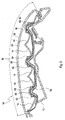
- Fig. 3 depicts a partial longitudinal cut through a detail of a preferred rear view mirror assembly as disclosed in EP 1 120 312 A2 , the disclosure of which is hereby included by reference in its entirety.
- An exterior rearview mirror for vehicles is disclosed by EP 1 120 312 A2 which has a mirror head housing having a light-transmitting light plate arranged therein. At least one lighting unit is received in the mirror head housing and has at least one light source emitting light rays so as to pass through the fight-transmitting light pane to the exterior of the mirror head housing. At least one reflector is positioned between the at least one light source and the light-transmitting light plate. The at least one reflector has at least one opening, and the at least one light source is positioned in the at least one opening.
- the at least one lighting unit has a lighting unit housing and the at least one light source is arranged in the lighting unit housing which is received in a receptacle of the mirror head housing.
- one or more IR light sources 40 are implemented in the turn-indicator light module 10 additional to a multitude of visible-light emitting light sources 50 such as LEDs which are arranged in reflectors 14. IR light and visible light can exit the light guiding element 20 all along its longitudinal extensions 18 between a first end 26 and a second end 28 on the front sides of the light guiding elements 20, the front side forming light emitting surfaces 38 of the turn-indicator light module 10.
- the light guiding element 20 forms the light pane 30 of the turn-indicator light module 10.
- the IR and the visible light is coupled in the light guiding element 20 along its longitudinal extension 18.
- the light guiding element 20 is formed in a way to follow smoothly the contour of the turn-light indicator module 10.
- Visible-light emitting light sources 50 are located in the vertex of each of several paraboloidically shaped reflectors 14.
- the reflectors 14 are covered by a light pane 30.
- Electrical connections are provided by a foil 54 which connects the LEDs of the turn-indicator light module 10 with a power supply (not shown).
- a protecting cover 56 is arranged between the foil 54 and the reflectors 14 which protects the foil 54 against moisture, dirt and the like.
- the light pane 30 is preferably embodied as a light guiding element 20.
- the IR light source 40 can be arranged at one of the locations of the visible-light emitting light sources 50 or as indicated close to one end of the light pane 30.
- Fig. 4 depicts a partial longitudinal cut through a preferred rear view mirror assembly comprising a preferred turn-indicator light module 10 as a turn indicator as disclosed in EP 0 941 892 A2 the disclosure of which is hereby included by reference in its entirety.
- one or more IR light sources 40 are implemented in the turn-indicator light module 10.
- the rear view mirror disclosed in EP 0 941 892 A2 has an LED as visible light source protruding partially from the opening of the covering section.
- LEDs are arranged on the end surface of the opening, facing away from the car, over the length and/or breadth of the light transmitting light pane.
- the LEDs are arranged behind an optical element formed by a Fresnel lens.
- the Fresnel lens is located in the area between the cover section and the light window.
- the lens is connected with the covering section.
- the LEDs are located in a housing, connected to the cover section.
- the housing is located on the side of the cover section turned away from the light window.
- a U-shaped fluorescent tube can be used as the visible light source
- a separate light guiding element 21 is provided for the one or more IR light emitting light sources 40, which overlays a light emitting surface 38 of a light pane 30 provided for a multitude of visible-light emitting light sources 50 positioned in a housing 68 beneath a Fresnel optical element 58.
- the Fresnel optical element 58 is placed in a cut-out of a mirror housing 64 and allows the emission of visible light through the light pane 30 more or less perpendicular to its longitudinal extension.
- the separate IR light guiding element 21 is extending from a first end 26 to a second end 28 with its longitudinal extension 18.
- IR light can exit the separate light guiding element 21 along its longitudinal extension 18 through its light emitting surface parallel to the light emitting surface 38 of the visible light.
- the IR light source 40 is located at the first end 26 of the light guiding element 20, coupled in the light guiding element 20 and transmitted to the separate light guiding element 21.
- the light guiding element 20 is formed in a way to follow smoothly the contour of the turn-light indicator module 10.
- the light pane 30 can be embodied as a light guiding element 20.
- An additional visible-light emitting light source 50 is placed at one end of the light pane 30 the light of which is transmitted towards the opposite end 28 of the light pane 30
- an IR emitting light source 40 can be placed, the IR light of which can be coupled preferably into the light guiding element 21.
- Fig. 5 depicts a preferred rear view mirror assembly 60 equipped with a preferred turn-indicator light module 10 as disclosed in EP 0 997 346 A1 the disclosure of which is hereby included by reference in its entirety.
- the mirror assembly 60 is attached to a vehicle body with a mirror foot 70.
- one or more IR light sources 40 are implemented in the turn-indicator light module 10 in the mirror head 62 of the mirror assembly 60.
- a light pane 30 which is embodied as light guiding element 20 forms a cover of the turn-indicator light module 10.
- the external rear view mirror according to EP 0 997 346 A1 has a mirror foot and a mirror head, which has a mirror glass carrier, and in which at least one turn-light indicator module is accommodated, which lies behind a light transmitting light pane.
- the turn-light indicator module is arranged in the mirror head in a way that it emits light in the main direction of motion of the vehicle rearwards at an angle of at least 55 degrees with reference to a straight line running outside the contour of the mirror head, lying parallel to the vehicle axis.
- the angle range may be least 60 degrees.
- the turn-light indicator module is located in the front of an ellipsoidal reflector, in a focal point of the reflector. In another focal point, the light beams reflected by the reflector intersect each other.
- a visible-light emitting light source 50 can be placed which illuminates the end 72.
- one or more visible-light emitting light sources 50 can be arranged.
- An IR emitting light source 40 can be placed at the end 72 and/or inside the housing 64. The light emitted by the IR emitting light source 40 can be coupled into the light guiding element 20 and illuminate the ambient of the vehicle.
- the light guiding element 20 has a longitudinal extension 18 which follows smoothly the contour of the turn-indicator light module 10 and the mirror housing 64.
- IR emitting light sources 40 By implementing one or more IR emitting light sources 40 in the turn-indicator light modules 10 of the various embodiments shown in the Figs. 1-5 , it is possible to illuminate fields of view 102, 104, 106 of a vehicle 100 which are illuminated by the visible-light emitting light sources 50 of the turn-indicator light module 10 and the mirror assembly 60 in which the turn-indicator light module 10 is incorporated.
- a driver 110 in a normal seating position, indicated by a pair of eyes, can use the rear vision mirror assembly 60 in its conventional way while the turn-indicator light module 10 allows for illuminating various areas with visible light and/or IR light for various sensors such as e.g. a pre-crash sensor using a field of vision 102, a bird-view sensor using the field of vision 104 and/or a blind-spot-detection sensor making use of the field of vision
Landscapes
- Engineering & Computer Science (AREA)
- General Engineering & Computer Science (AREA)
- Mechanical Engineering (AREA)
- Multimedia (AREA)
- Lighting Device Outwards From Vehicle And Optical Signal (AREA)
Priority Applications (2)
| Application Number | Priority Date | Filing Date | Title |
|---|---|---|---|
| EP09006001A EP2119595B1 (de) | 2008-05-16 | 2009-04-30 | Blinkermodul für eine Fahrzeugspiegelanordnung und Fahrzeugspiegelanordnung mit einem Blinkermodul |
| US12/466,106 US8477044B2 (en) | 2008-05-16 | 2009-05-14 | Turn-indicator light module for a vehicle mirror assembly and vehicle mirror assembly comprising a turn-indicator light module |
Applications Claiming Priority (2)
| Application Number | Priority Date | Filing Date | Title |
|---|---|---|---|
| EP08009048A EP2123514A1 (de) | 2008-05-16 | 2008-05-16 | Lichtmodul für eine Fahrzeugspiegelanordnung und Fahrzeugspiegelanordnung mit einem Lichtmodul |
| EP09006001A EP2119595B1 (de) | 2008-05-16 | 2009-04-30 | Blinkermodul für eine Fahrzeugspiegelanordnung und Fahrzeugspiegelanordnung mit einem Blinkermodul |
Publications (2)
| Publication Number | Publication Date |
|---|---|
| EP2119595A1 true EP2119595A1 (de) | 2009-11-18 |
| EP2119595B1 EP2119595B1 (de) | 2012-11-28 |
Family
ID=39811963
Family Applications (2)
| Application Number | Title | Priority Date | Filing Date |
|---|---|---|---|
| EP08009048A Withdrawn EP2123514A1 (de) | 2008-05-16 | 2008-05-16 | Lichtmodul für eine Fahrzeugspiegelanordnung und Fahrzeugspiegelanordnung mit einem Lichtmodul |
| EP09006001A Active EP2119595B1 (de) | 2008-05-16 | 2009-04-30 | Blinkermodul für eine Fahrzeugspiegelanordnung und Fahrzeugspiegelanordnung mit einem Blinkermodul |
Family Applications Before (1)
| Application Number | Title | Priority Date | Filing Date |
|---|---|---|---|
| EP08009048A Withdrawn EP2123514A1 (de) | 2008-05-16 | 2008-05-16 | Lichtmodul für eine Fahrzeugspiegelanordnung und Fahrzeugspiegelanordnung mit einem Lichtmodul |
Country Status (2)
| Country | Link |
|---|---|
| US (1) | US8477044B2 (de) |
| EP (2) | EP2123514A1 (de) |
Cited By (10)
| Publication number | Priority date | Publication date | Assignee | Title |
|---|---|---|---|---|
| DE102011016404A1 (de) * | 2011-04-08 | 2012-10-11 | GM Global Technology Operations LLC (n. d. Gesetzen des Staates Delaware) | Optikvorrichtung |
| EP2762361A1 (de) * | 2010-12-10 | 2014-08-06 | SMR Patents S.à.r.l. | Beleuchtungseinheit |
| EP2853444A1 (de) * | 2013-09-26 | 2015-04-01 | Fico Mirrors S.A. | Spiegelvorrichtung für Kraftfahrzeuge und Verfahren zum Zusammenbau derselben |
| CN108302495A (zh) * | 2016-09-23 | 2018-07-20 | 株式会社小糸制作所 | 车辆用灯具以及车体外后视装置 |
| US10539294B2 (en) | 2015-01-19 | 2020-01-21 | SMR Patents S.à.r.l. | Automobile exterior rear view mirror blind spot warning indication device |
| KR20220044950A (ko) * | 2019-07-29 | 2022-04-12 | 마더슨 이노베이션스 컴퍼니 리미티드 | 내부 리어뷰 미러 및 차량 |
| EP3981648A1 (de) * | 2017-08-25 | 2022-04-13 | SMR Patents S.à.r.l. | Rückblickvorrichtung und fahrzeug mit solch einer rückblickvorrichtung |
| US11305696B2 (en) | 2017-08-25 | 2022-04-19 | SMR Patents S.à.r.l. | Rearview device and vehicle with such rearview device |
| CN117989483A (zh) * | 2022-11-01 | 2024-05-07 | 玛泽森创新有限公司 | 用于车辆的后视装置的照明装置 |
| WO2024240761A1 (fr) * | 2023-05-25 | 2024-11-28 | Valeo Vision | Element optique pour vehicule avec relief a motif regulier a au moins deux profondeurs |
Families Citing this family (19)
| Publication number | Priority date | Publication date | Assignee | Title |
|---|---|---|---|---|
| CZ306862B6 (cs) * | 2011-06-23 | 2017-08-16 | Varroc Lighting Systems, s.r.o. | Reflektorová signální svítilna se skrytým zdrojem světla |
| US11220217B2 (en) * | 2013-01-24 | 2022-01-11 | SMR Patents S.à.r.l. | Rearview device with moveable head assembly and method of assembling same |
| JP5937836B2 (ja) * | 2012-02-07 | 2016-06-22 | 株式会社小糸製作所 | 車両用灯具 |
| JP2015173057A (ja) * | 2014-03-12 | 2015-10-01 | ヤマハ株式会社 | 音響機器及びその線状照明具用ブラケット |
| KR101592676B1 (ko) * | 2014-03-20 | 2016-02-12 | 현대자동차주식회사 | 면 발광이 가능한 거울 및 이를 이용한 자동차용 사이드미러 시스템 |
| JP2016137753A (ja) * | 2015-01-26 | 2016-08-04 | 株式会社東海理化電機製作所 | 車両用方向指示装置 |
| DE102015104163A1 (de) * | 2015-03-19 | 2016-09-22 | SMR Patents S.à.r.l. | Leuchteinrichtung und Verfahren zur Herstellung einer Leuchteinrichtung |
| US9697393B2 (en) | 2015-11-20 | 2017-07-04 | Symbol Technologies, Llc | Methods and systems for adjusting mobile-device operating parameters based on housing-support type |
| DE102016101997A1 (de) * | 2016-02-04 | 2017-08-10 | SMR Patents S.à.r.l. | Beleuchtungseinrichtung und Rückblickeinrichtung für Fahrzeuge |
| WO2017159189A1 (ja) * | 2016-03-17 | 2017-09-21 | 本田技研工業株式会社 | 車両用灯具 |
| US10184635B2 (en) | 2016-10-24 | 2019-01-22 | Varroc Lighting Systems, s.r.o. | Light device |
| CN106828324B (zh) * | 2017-01-25 | 2023-10-20 | 宁波胜维德赫华翔汽车镜有限公司 | 汽车外后视镜的盲区警告指示装置 |
| CN110500553A (zh) * | 2018-05-16 | 2019-11-26 | 深圳市绎立锐光科技开发有限公司 | 光源装置及汽车前照灯 |
| US11396986B2 (en) | 2019-05-23 | 2022-07-26 | Valeo North America, Inc. | Apparatus and method for masking residual visible light from an infrared emission source |
| DE102020108943B4 (de) * | 2020-03-31 | 2022-04-28 | HELLA GmbH & Co. KGaA | Beleuchtungsvorrichtung für Fahrzeuge |
| JP7671290B2 (ja) * | 2020-07-15 | 2025-05-01 | 株式会社小糸製作所 | 車両用灯具、アクティブセンサ用の照明装置、ゲーティングカメラ |
| DE102020128316B3 (de) | 2020-10-28 | 2022-03-24 | Zkw Group Gmbh | Kraftfahrzeugscheinwerfer zur erfassung einer kraftfahrzeugumgebung |
| JP7837896B2 (ja) * | 2023-01-17 | 2026-03-31 | トヨタ自動車東日本株式会社 | アウターミラー |
| US12135116B1 (en) * | 2024-02-22 | 2024-11-05 | Motherson Innovations Company Limited | Multi-functional light module for an exterior mirror |
Citations (12)
| Publication number | Priority date | Publication date | Assignee | Title |
|---|---|---|---|---|
| EP0941892A2 (de) | 1998-03-13 | 1999-09-15 | Reitter & Schefenacker GmbH & Co. KG | Aussenrückblickspiegel für Fahrzeuge, vorzugsweise für Kraftfahrzeuge |
| EP0997346A1 (de) | 1998-10-29 | 2000-05-03 | Reitter & Schefenacker GmbH & Co. KG | Aussenrückspiegel für Fahrzeuge, insbesondere Kraftfahrzeuge |
| US6160948A (en) * | 1997-05-21 | 2000-12-12 | Mcgaffigan; Thomas H. | Optical light pipes with laser light appearance |
| EP1120312A2 (de) | 2000-01-27 | 2001-08-01 | Reitter & Schefenacker GmbH & Co. KG | Aussenrückblickspiegel für Fahrzeuge, vorzugsweise für Kraftfahrzeuge |
| EP1391755A2 (de) * | 2002-08-21 | 2004-02-25 | Hella KG Hueck & Co. | Fahrzeugleuchte |
| EP1466785A1 (de) | 2003-04-09 | 2004-10-13 | Toyota Jidosha Kabushiki Kaisha | Fahrrichtungsanzeigeleuchte, Umfeldüberwachtungsvorrichtung, Gehäuse und Bildaufnahmevorrichtung für Kraftfahrzeug |
| WO2005075247A1 (de) * | 2004-02-06 | 2005-08-18 | Daimlerchrysler Ag | Fahrzeug mit infrarotbeleuchter |
| US20050243568A1 (en) | 2000-07-12 | 2005-11-03 | Alejandro Rodriguez Barros | Set of parts and assembling method for assembling a rear-view side mirror of a vehicle |
| EP1657111A2 (de) | 2004-11-15 | 2006-05-17 | FER Fahrzeugelektrik GmbH | Seitenblinkleuchte |
| DE102005013682A1 (de) | 2005-03-18 | 2006-09-21 | Schefenacker Vision Systems Germany Gmbh | Außenrückblickspiegel von Fahrzeugen, vorzugsweise von Kraftfahrzeugen |
| DE102005019018A1 (de) * | 2005-04-23 | 2006-10-26 | Volkswagen Ag | Leuchte mit wenigstens einem Lichtleiter und mehreren Lichtquellen |
| DE102006007884A1 (de) * | 2006-02-21 | 2007-08-30 | Daimlerchrysler Ag | Leuchtenanordnung an einem Kraftfahrzeug-Außenspiegel |
Family Cites Families (6)
| Publication number | Priority date | Publication date | Assignee | Title |
|---|---|---|---|---|
| US7049945B2 (en) | 2000-05-08 | 2006-05-23 | Automotive Technologies International, Inc. | Vehicular blind spot identification and monitoring system |
| DE10218437A1 (de) * | 2002-04-25 | 2004-01-15 | Hella Kg Hueck & Co. | Leuchteinheit für Fahrzeuge |
| US20040218041A1 (en) * | 2003-01-30 | 2004-11-04 | Ichikoh Industries, Ltd. | Outside mirror for vehicle |
| DE102004048669B4 (de) * | 2003-10-07 | 2007-06-14 | Toyoda Gosei Co., Ltd. | Fahrzeugseitenspiegelgerät |
| JP4791262B2 (ja) * | 2006-06-14 | 2011-10-12 | 本田技研工業株式会社 | 運転支援装置 |
| JP4276250B2 (ja) * | 2006-10-11 | 2009-06-10 | 株式会社ミツバ | ターンランプ付きドアミラー |
-
2008
- 2008-05-16 EP EP08009048A patent/EP2123514A1/de not_active Withdrawn
-
2009
- 2009-04-30 EP EP09006001A patent/EP2119595B1/de active Active
- 2009-05-14 US US12/466,106 patent/US8477044B2/en active Active
Patent Citations (12)
| Publication number | Priority date | Publication date | Assignee | Title |
|---|---|---|---|---|
| US6160948A (en) * | 1997-05-21 | 2000-12-12 | Mcgaffigan; Thomas H. | Optical light pipes with laser light appearance |
| EP0941892A2 (de) | 1998-03-13 | 1999-09-15 | Reitter & Schefenacker GmbH & Co. KG | Aussenrückblickspiegel für Fahrzeuge, vorzugsweise für Kraftfahrzeuge |
| EP0997346A1 (de) | 1998-10-29 | 2000-05-03 | Reitter & Schefenacker GmbH & Co. KG | Aussenrückspiegel für Fahrzeuge, insbesondere Kraftfahrzeuge |
| EP1120312A2 (de) | 2000-01-27 | 2001-08-01 | Reitter & Schefenacker GmbH & Co. KG | Aussenrückblickspiegel für Fahrzeuge, vorzugsweise für Kraftfahrzeuge |
| US20050243568A1 (en) | 2000-07-12 | 2005-11-03 | Alejandro Rodriguez Barros | Set of parts and assembling method for assembling a rear-view side mirror of a vehicle |
| EP1391755A2 (de) * | 2002-08-21 | 2004-02-25 | Hella KG Hueck & Co. | Fahrzeugleuchte |
| EP1466785A1 (de) | 2003-04-09 | 2004-10-13 | Toyota Jidosha Kabushiki Kaisha | Fahrrichtungsanzeigeleuchte, Umfeldüberwachtungsvorrichtung, Gehäuse und Bildaufnahmevorrichtung für Kraftfahrzeug |
| WO2005075247A1 (de) * | 2004-02-06 | 2005-08-18 | Daimlerchrysler Ag | Fahrzeug mit infrarotbeleuchter |
| EP1657111A2 (de) | 2004-11-15 | 2006-05-17 | FER Fahrzeugelektrik GmbH | Seitenblinkleuchte |
| DE102005013682A1 (de) | 2005-03-18 | 2006-09-21 | Schefenacker Vision Systems Germany Gmbh | Außenrückblickspiegel von Fahrzeugen, vorzugsweise von Kraftfahrzeugen |
| DE102005019018A1 (de) * | 2005-04-23 | 2006-10-26 | Volkswagen Ag | Leuchte mit wenigstens einem Lichtleiter und mehreren Lichtquellen |
| DE102006007884A1 (de) * | 2006-02-21 | 2007-08-30 | Daimlerchrysler Ag | Leuchtenanordnung an einem Kraftfahrzeug-Außenspiegel |
Cited By (16)
| Publication number | Priority date | Publication date | Assignee | Title |
|---|---|---|---|---|
| EP2762361A1 (de) * | 2010-12-10 | 2014-08-06 | SMR Patents S.à.r.l. | Beleuchtungseinheit |
| DE102011016404A1 (de) * | 2011-04-08 | 2012-10-11 | GM Global Technology Operations LLC (n. d. Gesetzen des Staates Delaware) | Optikvorrichtung |
| EP2853444A1 (de) * | 2013-09-26 | 2015-04-01 | Fico Mirrors S.A. | Spiegelvorrichtung für Kraftfahrzeuge und Verfahren zum Zusammenbau derselben |
| US10274155B2 (en) | 2013-09-26 | 2019-04-30 | Fico Mirrors, S.A. | Mirror device for motor vehicles and method for assembling thereof |
| US10539294B2 (en) | 2015-01-19 | 2020-01-21 | SMR Patents S.à.r.l. | Automobile exterior rear view mirror blind spot warning indication device |
| CN108302495A (zh) * | 2016-09-23 | 2018-07-20 | 株式会社小糸制作所 | 车辆用灯具以及车体外后视装置 |
| EP3981648A1 (de) * | 2017-08-25 | 2022-04-13 | SMR Patents S.à.r.l. | Rückblickvorrichtung und fahrzeug mit solch einer rückblickvorrichtung |
| US11305696B2 (en) | 2017-08-25 | 2022-04-19 | SMR Patents S.à.r.l. | Rearview device and vehicle with such rearview device |
| US11738689B2 (en) | 2017-08-25 | 2023-08-29 | SMR Patents S.à.r.l. | Rearview device and vehicle with such rearview device |
| US12286058B2 (en) | 2017-08-25 | 2025-04-29 | SMR Patents S.à.r.l. | Rearview device and vehicle with such rearview device |
| KR20220044951A (ko) * | 2019-07-29 | 2022-04-12 | 마더슨 이노베이션스 컴퍼니 리미티드 | 회로기판이 장착된 차량용 리어뷰 디바이스 |
| KR20220044950A (ko) * | 2019-07-29 | 2022-04-12 | 마더슨 이노베이션스 컴퍼니 리미티드 | 내부 리어뷰 미러 및 차량 |
| CN117989483A (zh) * | 2022-11-01 | 2024-05-07 | 玛泽森创新有限公司 | 用于车辆的后视装置的照明装置 |
| GB2624115A (en) * | 2022-11-01 | 2024-05-08 | Motherson Innovations Co Ltd | Lighting device for rear-view device of vehicle |
| GB2624115B (en) * | 2022-11-01 | 2024-10-23 | Motherson Innovations Co Ltd | Lighting device for rear-view device of vehicle |
| WO2024240761A1 (fr) * | 2023-05-25 | 2024-11-28 | Valeo Vision | Element optique pour vehicule avec relief a motif regulier a au moins deux profondeurs |
Also Published As
| Publication number | Publication date |
|---|---|
| US20090284365A1 (en) | 2009-11-19 |
| EP2123514A1 (de) | 2009-11-25 |
| US8477044B2 (en) | 2013-07-02 |
| EP2119595B1 (de) | 2012-11-28 |
Similar Documents
| Publication | Publication Date | Title |
|---|---|---|
| EP2119595B1 (de) | Blinkermodul für eine Fahrzeugspiegelanordnung und Fahrzeugspiegelanordnung mit einem Blinkermodul | |
| US12420712B2 (en) | Vehicular exterior mirror system with light module | |
| EP2157363B1 (de) | Optisches Element für eine Fahrzeugleuchte | |
| KR100950636B1 (ko) | 차량의 외부 후사경 | |
| US9360183B2 (en) | Mirror apparatus for a vehicle | |
| US20110157907A1 (en) | Turn-indicator light module for a vehicle mirror assembly and vehicle mirror assembly comprising a turn-indicator light module | |
| EP1442934B1 (de) | Aussenspiegel für Fahrzeuge | |
| US8177401B2 (en) | Light guide turn signal indicator rear view mirror | |
| EP1442930B1 (de) | Fahrzeugaussenspiegel mit Leuchte | |
| CN105083108A (zh) | 照明单元 | |
| KR20190068808A (ko) | 차량의 루프 간접조명 구조 | |
| CN106979493A (zh) | 跨过封闭间隙的照明源 | |
| US7204625B2 (en) | Phototherapy device | |
| CN1409673A (zh) | 具有发光装置的车辆用外后视镜 | |
| WO2024094692A1 (en) | Lighting device for rear-view device of vehicle | |
| US20240218999A1 (en) | Tail Light for a Motor Vehicle | |
| JP4214882B2 (ja) | 車両周辺暗視用灯具および車両用アウトサイドミラー装置 | |
| KR101428097B1 (ko) | 차량용 램프 | |
| EP1498311B1 (de) | Infrarotprojektor | |
| US20050036329A1 (en) | Motor-vehicle headlight | |
| JP2002236178A (ja) | 移動体における物体検知装置 | |
| CN120129622A (zh) | 用于车辆的后视装置的照明装置 | |
| US8425095B2 (en) | Mirror assembly | |
| JP7764274B2 (ja) | 車両後方照射システム | |
| KR200284078Y1 (ko) | 다기능 램프가 장착된 자동차용 리어백미러 |
Legal Events
| Date | Code | Title | Description |
|---|---|---|---|
| PUAI | Public reference made under article 153(3) epc to a published international application that has entered the european phase |
Free format text: ORIGINAL CODE: 0009012 |
|
| AK | Designated contracting states |
Kind code of ref document: A1 Designated state(s): AT BE BG CH CY CZ DE DK EE ES FI FR GB GR HR HU IE IS IT LI LT LU LV MC MK MT NL NO PL PT RO SE SI SK TR |
|
| 17P | Request for examination filed |
Effective date: 20091023 |
|
| 17Q | First examination report despatched |
Effective date: 20100204 |
|
| GRAP | Despatch of communication of intention to grant a patent |
Free format text: ORIGINAL CODE: EPIDOSNIGR1 |
|
| GRAS | Grant fee paid |
Free format text: ORIGINAL CODE: EPIDOSNIGR3 |
|
| GRAA | (expected) grant |
Free format text: ORIGINAL CODE: 0009210 |
|
| AK | Designated contracting states |
Kind code of ref document: B1 Designated state(s): AT BE BG CH CY CZ DE DK EE ES FI FR GB GR HR HU IE IS IT LI LT LU LV MC MK MT NL NO PL PT RO SE SI SK TR |
|
| REG | Reference to a national code |
Ref country code: GB Ref legal event code: FG4D |
|
| REG | Reference to a national code |
Ref country code: CH Ref legal event code: EP |
|
| REG | Reference to a national code |
Ref country code: AT Ref legal event code: REF Ref document number: 585971 Country of ref document: AT Kind code of ref document: T Effective date: 20121215 |
|
| REG | Reference to a national code |
Ref country code: IE Ref legal event code: FG4D |
|
| REG | Reference to a national code |
Ref country code: DE Ref legal event code: R096 Ref document number: 602009011471 Country of ref document: DE Effective date: 20130124 |
|
| REG | Reference to a national code |
Ref country code: AT Ref legal event code: MK05 Ref document number: 585971 Country of ref document: AT Kind code of ref document: T Effective date: 20121128 |
|
| REG | Reference to a national code |
Ref country code: NL Ref legal event code: VDEP Effective date: 20121128 |
|
| REG | Reference to a national code |
Ref country code: LT Ref legal event code: MG4D |
|
| PG25 | Lapsed in a contracting state [announced via postgrant information from national office to epo] |
Ref country code: FI Free format text: LAPSE BECAUSE OF FAILURE TO SUBMIT A TRANSLATION OF THE DESCRIPTION OR TO PAY THE FEE WITHIN THE PRESCRIBED TIME-LIMIT Effective date: 20121128 Ref country code: SE Free format text: LAPSE BECAUSE OF FAILURE TO SUBMIT A TRANSLATION OF THE DESCRIPTION OR TO PAY THE FEE WITHIN THE PRESCRIBED TIME-LIMIT Effective date: 20121128 Ref country code: ES Free format text: LAPSE BECAUSE OF FAILURE TO SUBMIT A TRANSLATION OF THE DESCRIPTION OR TO PAY THE FEE WITHIN THE PRESCRIBED TIME-LIMIT Effective date: 20130311 Ref country code: LT Free format text: LAPSE BECAUSE OF FAILURE TO SUBMIT A TRANSLATION OF THE DESCRIPTION OR TO PAY THE FEE WITHIN THE PRESCRIBED TIME-LIMIT Effective date: 20121128 Ref country code: NO Free format text: LAPSE BECAUSE OF FAILURE TO SUBMIT A TRANSLATION OF THE DESCRIPTION OR TO PAY THE FEE WITHIN THE PRESCRIBED TIME-LIMIT Effective date: 20130228 |
|
| PG25 | Lapsed in a contracting state [announced via postgrant information from national office to epo] |
Ref country code: LV Free format text: LAPSE BECAUSE OF FAILURE TO SUBMIT A TRANSLATION OF THE DESCRIPTION OR TO PAY THE FEE WITHIN THE PRESCRIBED TIME-LIMIT Effective date: 20121128 Ref country code: PT Free format text: LAPSE BECAUSE OF FAILURE TO SUBMIT A TRANSLATION OF THE DESCRIPTION OR TO PAY THE FEE WITHIN THE PRESCRIBED TIME-LIMIT Effective date: 20130328 Ref country code: BE Free format text: LAPSE BECAUSE OF FAILURE TO SUBMIT A TRANSLATION OF THE DESCRIPTION OR TO PAY THE FEE WITHIN THE PRESCRIBED TIME-LIMIT Effective date: 20121128 Ref country code: PL Free format text: LAPSE BECAUSE OF FAILURE TO SUBMIT A TRANSLATION OF THE DESCRIPTION OR TO PAY THE FEE WITHIN THE PRESCRIBED TIME-LIMIT Effective date: 20121128 Ref country code: GR Free format text: LAPSE BECAUSE OF FAILURE TO SUBMIT A TRANSLATION OF THE DESCRIPTION OR TO PAY THE FEE WITHIN THE PRESCRIBED TIME-LIMIT Effective date: 20130301 Ref country code: SI Free format text: LAPSE BECAUSE OF FAILURE TO SUBMIT A TRANSLATION OF THE DESCRIPTION OR TO PAY THE FEE WITHIN THE PRESCRIBED TIME-LIMIT Effective date: 20121128 Ref country code: CY Free format text: LAPSE BECAUSE OF FAILURE TO SUBMIT A TRANSLATION OF THE DESCRIPTION OR TO PAY THE FEE WITHIN THE PRESCRIBED TIME-LIMIT Effective date: 20121128 |
|
| PG25 | Lapsed in a contracting state [announced via postgrant information from national office to epo] |
Ref country code: AT Free format text: LAPSE BECAUSE OF FAILURE TO SUBMIT A TRANSLATION OF THE DESCRIPTION OR TO PAY THE FEE WITHIN THE PRESCRIBED TIME-LIMIT Effective date: 20121128 |
|
| PG25 | Lapsed in a contracting state [announced via postgrant information from national office to epo] |
Ref country code: EE Free format text: LAPSE BECAUSE OF FAILURE TO SUBMIT A TRANSLATION OF THE DESCRIPTION OR TO PAY THE FEE WITHIN THE PRESCRIBED TIME-LIMIT Effective date: 20121128 Ref country code: SK Free format text: LAPSE BECAUSE OF FAILURE TO SUBMIT A TRANSLATION OF THE DESCRIPTION OR TO PAY THE FEE WITHIN THE PRESCRIBED TIME-LIMIT Effective date: 20121128 Ref country code: CZ Free format text: LAPSE BECAUSE OF FAILURE TO SUBMIT A TRANSLATION OF THE DESCRIPTION OR TO PAY THE FEE WITHIN THE PRESCRIBED TIME-LIMIT Effective date: 20121128 Ref country code: BG Free format text: LAPSE BECAUSE OF FAILURE TO SUBMIT A TRANSLATION OF THE DESCRIPTION OR TO PAY THE FEE WITHIN THE PRESCRIBED TIME-LIMIT Effective date: 20130228 Ref country code: DK Free format text: LAPSE BECAUSE OF FAILURE TO SUBMIT A TRANSLATION OF THE DESCRIPTION OR TO PAY THE FEE WITHIN THE PRESCRIBED TIME-LIMIT Effective date: 20121128 |
|
| PG25 | Lapsed in a contracting state [announced via postgrant information from national office to epo] |
Ref country code: RO Free format text: LAPSE BECAUSE OF FAILURE TO SUBMIT A TRANSLATION OF THE DESCRIPTION OR TO PAY THE FEE WITHIN THE PRESCRIBED TIME-LIMIT Effective date: 20121128 Ref country code: IT Free format text: LAPSE BECAUSE OF FAILURE TO SUBMIT A TRANSLATION OF THE DESCRIPTION OR TO PAY THE FEE WITHIN THE PRESCRIBED TIME-LIMIT Effective date: 20121128 Ref country code: NL Free format text: LAPSE BECAUSE OF FAILURE TO SUBMIT A TRANSLATION OF THE DESCRIPTION OR TO PAY THE FEE WITHIN THE PRESCRIBED TIME-LIMIT Effective date: 20121128 |
|
| PLBE | No opposition filed within time limit |
Free format text: ORIGINAL CODE: 0009261 |
|
| STAA | Information on the status of an ep patent application or granted ep patent |
Free format text: STATUS: NO OPPOSITION FILED WITHIN TIME LIMIT |
|
| 26N | No opposition filed |
Effective date: 20130829 |
|
| PG25 | Lapsed in a contracting state [announced via postgrant information from national office to epo] |
Ref country code: MC Free format text: LAPSE BECAUSE OF FAILURE TO SUBMIT A TRANSLATION OF THE DESCRIPTION OR TO PAY THE FEE WITHIN THE PRESCRIBED TIME-LIMIT Effective date: 20121128 |
|
| REG | Reference to a national code |
Ref country code: CH Ref legal event code: PL |
|
| REG | Reference to a national code |
Ref country code: DE Ref legal event code: R097 Ref document number: 602009011471 Country of ref document: DE Effective date: 20130829 |
|
| REG | Reference to a national code |
Ref country code: IE Ref legal event code: MM4A |
|
| PG25 | Lapsed in a contracting state [announced via postgrant information from national office to epo] |
Ref country code: HR Free format text: LAPSE BECAUSE OF FAILURE TO SUBMIT A TRANSLATION OF THE DESCRIPTION OR TO PAY THE FEE WITHIN THE PRESCRIBED TIME-LIMIT Effective date: 20130731 Ref country code: LI Free format text: LAPSE BECAUSE OF NON-PAYMENT OF DUE FEES Effective date: 20130430 Ref country code: CH Free format text: LAPSE BECAUSE OF NON-PAYMENT OF DUE FEES Effective date: 20130430 |
|
| PG25 | Lapsed in a contracting state [announced via postgrant information from national office to epo] |
Ref country code: IE Free format text: LAPSE BECAUSE OF NON-PAYMENT OF DUE FEES Effective date: 20130430 |
|
| PG25 | Lapsed in a contracting state [announced via postgrant information from national office to epo] |
Ref country code: MT Free format text: LAPSE BECAUSE OF FAILURE TO SUBMIT A TRANSLATION OF THE DESCRIPTION OR TO PAY THE FEE WITHIN THE PRESCRIBED TIME-LIMIT Effective date: 20121128 |
|
| PG25 | Lapsed in a contracting state [announced via postgrant information from national office to epo] |
Ref country code: TR Free format text: LAPSE BECAUSE OF FAILURE TO SUBMIT A TRANSLATION OF THE DESCRIPTION OR TO PAY THE FEE WITHIN THE PRESCRIBED TIME-LIMIT Effective date: 20121128 |
|
| PG25 | Lapsed in a contracting state [announced via postgrant information from national office to epo] |
Ref country code: LU Free format text: LAPSE BECAUSE OF NON-PAYMENT OF DUE FEES Effective date: 20130430 Ref country code: HU Free format text: LAPSE BECAUSE OF FAILURE TO SUBMIT A TRANSLATION OF THE DESCRIPTION OR TO PAY THE FEE WITHIN THE PRESCRIBED TIME-LIMIT; INVALID AB INITIO Effective date: 20090430 Ref country code: MK Free format text: LAPSE BECAUSE OF FAILURE TO SUBMIT A TRANSLATION OF THE DESCRIPTION OR TO PAY THE FEE WITHIN THE PRESCRIBED TIME-LIMIT Effective date: 20121128 |
|
| REG | Reference to a national code |
Ref country code: FR Ref legal event code: PLFP Year of fee payment: 8 |
|
| PG25 | Lapsed in a contracting state [announced via postgrant information from national office to epo] |
Ref country code: IS Free format text: LAPSE BECAUSE OF FAILURE TO SUBMIT A TRANSLATION OF THE DESCRIPTION OR TO PAY THE FEE WITHIN THE PRESCRIBED TIME-LIMIT Effective date: 20121128 |
|
| REG | Reference to a national code |
Ref country code: FR Ref legal event code: PLFP Year of fee payment: 9 |
|
| REG | Reference to a national code |
Ref country code: FR Ref legal event code: PLFP Year of fee payment: 10 |
|
| REG | Reference to a national code |
Ref country code: DE Ref legal event code: R084 Ref document number: 602009011471 Country of ref document: DE |
|
| P01 | Opt-out of the competence of the unified patent court (upc) registered |
Effective date: 20230616 |
|
| PGFP | Annual fee paid to national office [announced via postgrant information from national office to epo] |
Ref country code: DE Payment date: 20250417 Year of fee payment: 17 |
|
| PGFP | Annual fee paid to national office [announced via postgrant information from national office to epo] |
Ref country code: GB Payment date: 20250423 Year of fee payment: 17 |
|
| PGFP | Annual fee paid to national office [announced via postgrant information from national office to epo] |
Ref country code: FR Payment date: 20250425 Year of fee payment: 17 |