EP2119626B1 - Ensemble de levier de contrôle pour avion à rotor basculant - Google Patents
Ensemble de levier de contrôle pour avion à rotor basculant Download PDFInfo
- Publication number
- EP2119626B1 EP2119626B1 EP08103976A EP08103976A EP2119626B1 EP 2119626 B1 EP2119626 B1 EP 2119626B1 EP 08103976 A EP08103976 A EP 08103976A EP 08103976 A EP08103976 A EP 08103976A EP 2119626 B1 EP2119626 B1 EP 2119626B1
- Authority
- EP
- European Patent Office
- Prior art keywords
- control lever
- aircraft
- control
- lever assembly
- assembly
- Prior art date
- Legal status (The legal status is an assumption and is not a legal conclusion. Google has not performed a legal analysis and makes no representation as to the accuracy of the status listed.)
- Ceased
Links
Images
Classifications
-
- B—PERFORMING OPERATIONS; TRANSPORTING
- B64—AIRCRAFT; AVIATION; COSMONAUTICS
- B64C—AEROPLANES; HELICOPTERS
- B64C13/00—Control systems or transmitting systems for actuating flying-control surfaces, lift-increasing flaps, air brakes, or spoilers
- B64C13/02—Initiating means
- B64C13/04—Initiating means actuated personally
- B64C13/042—Initiating means actuated personally operated by hand
-
- B—PERFORMING OPERATIONS; TRANSPORTING
- B64—AIRCRAFT; AVIATION; COSMONAUTICS
- B64C—AEROPLANES; HELICOPTERS
- B64C29/00—Aircraft capable of landing or taking-off vertically, e.g. vertical take-off and landing [VTOL] aircraft
- B64C29/0008—Aircraft capable of landing or taking-off vertically, e.g. vertical take-off and landing [VTOL] aircraft having its flight directional axis horizontal when grounded
- B64C29/0016—Aircraft capable of landing or taking-off vertically, e.g. vertical take-off and landing [VTOL] aircraft having its flight directional axis horizontal when grounded the lift during taking-off being created by free or ducted propellers or by blowers
- B64C29/0033—Aircraft capable of landing or taking-off vertically, e.g. vertical take-off and landing [VTOL] aircraft having its flight directional axis horizontal when grounded the lift during taking-off being created by free or ducted propellers or by blowers the propellers being tiltable relative to the fuselage
-
- B—PERFORMING OPERATIONS; TRANSPORTING
- B64—AIRCRAFT; AVIATION; COSMONAUTICS
- B64D—EQUIPMENT FOR FITTING IN OR TO AIRCRAFT; FLIGHT SUITS; PARACHUTES; ARRANGEMENT OR MOUNTING OF POWER PLANTS OR PROPULSION TRANSMISSIONS IN AIRCRAFT
- B64D31/00—Power plant control systems; Arrangement of power plant control systems in aircraft
- B64D31/02—Initiating means
- B64D31/04—Initiating means actuated personally
-
- G—PHYSICS
- G05—CONTROLLING; REGULATING
- G05G—CONTROL DEVICES OR SYSTEMS INSOFAR AS CHARACTERISED BY MECHANICAL FEATURES ONLY
- G05G1/00—Controlling members, e.g. knobs or handles; Assemblies or arrangements thereof; Indicating position of controlling members
- G05G1/04—Controlling members for hand actuation by pivoting movement, e.g. levers
-
- Y—GENERAL TAGGING OF NEW TECHNOLOGICAL DEVELOPMENTS; GENERAL TAGGING OF CROSS-SECTIONAL TECHNOLOGIES SPANNING OVER SEVERAL SECTIONS OF THE IPC; TECHNICAL SUBJECTS COVERED BY FORMER USPC CROSS-REFERENCE ART COLLECTIONS [XRACs] AND DIGESTS
- Y10—TECHNICAL SUBJECTS COVERED BY FORMER USPC
- Y10T—TECHNICAL SUBJECTS COVERED BY FORMER US CLASSIFICATION
- Y10T74/00—Machine element or mechanism
- Y10T74/20—Control lever and linkage systems
- Y10T74/20576—Elements
- Y10T74/20582—Levers
Definitions
- the invention relates to a control lever assembly according to the preambule of claim 1.
- a control lever assembly is known from US-A-3360219 , which constitutes the closes prior art.
- the engine nacelles can be rotated from a position in which the engine thrust is directed substantially horizontally and backwards and the aircraft is in an airplane mode, towards a position in which the engine thrust is directed substantially vertically and downwards and the aircraft is in a helicopter mode.
- the control lever assembly is used to control the engines, aided by a special power and thrust management system.
- the power and thrust management system will in a predefined manner control the engines (especially the rotor rpm and engine power output) based upon the position of the control lever(s) relative to the control lever support.
- control lever support has a fixed position (generally in accordance with a conventional rotorcraft, such that the control lever may be moved up or down for the control of the rotor blade collective pitch angle)
- the position of the control lever support will be varied in accordance with the tilt of the rotor (or, in other words, according to the mode of the aircraft).
- the control lever position and the control lever movement will correspond better with such positions and movements in accordance with both a conventional airplane and a conventional helicopter. This will increase the 'natural' feel to the pilot, when in the airplane mode and helicopter mode, but also in a conversion mode.
- the rotational position of the control lever support (and control lever) will provide the pilot with a visible and tactile indication of the tilt position of the rotors/nacelles.
- control lever support is movable by an actuator between a first position, in the airplane mode of the aircraft, in which the control lever moves substantially horizontally, and a second position, in the helicopter mode of the aircraft, in which the control lever moves substantially vertically.
- control lever assembly in both modes closely mimics the respective position of such control lever assemblies in conventional airplanes and conventional helicopters.
- the actuator automatically provides the position of the control lever support in correspondence with the present flight mode.
- control lever support comprises a box pivotally connected to the remainder of the aircraft through a horizontally and transversally extending pivot axis.
- the box will rotate around the pivot axis between its first and second positions corresponding to the airplane mode and helicopter mode, respectively.
- the rotation of the box may be realised in different ways.
- the rotation of the box may be affected by a linear actuator, such as for example a cylinder piston assembly, connected to the remainder of the aircraft and to a part of the box distanced from the pivot axis.
- a linear actuator such as for example a cylinder piston assembly
- the rotation of the box is caused by a rotary actuator positioned at the pivot axis.
- means are provided for temporarily increasing the friction force experienced by the control lever during rotation of the control lever support.
- the control lever support (together with the control lever) rotates to a new position the increased friction enables the control lever to exert a force on the hand of the pilot without said control lever moving relative to the control lever support (and thus without changing the setting of the engine(s)).
- the pilot receives tactile feedback of the rotation of the engine nacelles.
- a friction provides the pilot with a feel as if the control lever is fixed to the control lever support. But the pilot will be able to overcome such friction, however, using a larger force than needed to move the control lever when the control lever support is not rotating.
- the friction force is programmable, such that the force to overcome the friction ('breakout force') can be set.
- control lever can rotate around a rotation axis defined by the control lever support.
- control lever follows an arc shaped path.
- rotation axis does not coincide with the pivot axis of the control lever support. It is noted, however, that it is also possible that the control lever translates, following a straight path.
- control lever is provided with at least one manually operable control switch.
- the pilot then can operate aircraft systems without removing his hand from the control lever.
- at least one control switch may be used for selecting the tilt of the rotor/nacelles of the aircraft.
- control lever assembly comprises a control unit for determining the tilt of the rotor and, based thereon, providing a control signal for the actuator for rotating the control lever support.
- a tilt sensor may be provided feeding a tilt signal to the control unit.
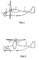
- a tilt-rotor aircraft 1 is illustrated schematically in outlines.
- the aircraft is in an airplane mode in which each rotor 2 faces substantially forward for creating a forward thrust for propelling the aircraft 1 in normal flight.
- the engine nacelles 3 substantially extend horizontally.
- the aircraft is in a helicopter mode in which each rotor 2 faces substantially upward for creating a upward thrust for hovering the aircraft 1, mainly during take-off and landing.
- the engine nacelles 3 substantially extend vertically.
- the aircraft will be in a conversion mode in which the rotor 2 (or nacelle 3) is inclined.
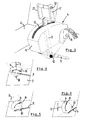
- a control lever assembly 4 with control lever 5 have been indicated schematically (it is noted that multiple control levers may be provided).
- the orientation of the control lever assembly 4 is such that for controlling the operation of the engines of the aircraft the control lever substantially is moved horizontally forward or rearward (as indicated by the short arrows).
- the orientation of the control lever assembly 4 is such that for controlling the operation of the engines of the aircraft the control lever 5 substantially is moved vertically upward or downward (as indicated by the short arrows). Also in this case, when the control lever rotates around a rotation axis, such a movement actually occurs along an arc of a circle.
- control lever assembly 4 in different flight modes offers a pilot a control lever assembly with a control lever movement similar to what is known from conventional airplanes and helicopters, respectively, and this offers a 'natural' control in both modes.
- control lever assembly will be used to control the engines in combination with a special power and thrust management system.
- the power and thrust management system will in a predefined manner control the engines (especially the rotor rpm and engine power output) based upon the position of the control levers relative to the control lever support.
- control lever 5 of the control lever assembly 4 for the tilt-rotor aircraft 1 is movably mounted in a control lever support that has a rotational position that varies in correspondence with the tilt of the rotor 2 of the aircraft 1.
- the control lever support comprises a box 6 pivotally connected to the remainder of the aircraft (for example a central console 7 in the cockpit) through a horizontally and transversally (with respect to the aircraft) extending pivot axis 8.
- the control lever support or box 6 is movable by an actuator 9 between a first position ( figure 4 ), in the airplane mode of the aircraft, in which the control lever 5 moves substantially horizontally and a second position ( figure 6 ), in the helicopter mode of the aircraft, in which the control lever 5 moves substantially vertically.
- the rotation of the box 6 is caused by a linear actuator 9, such as for example a cylinder piston assembly, connected with its one end to the remainder of the aircraft and with its other opposite end to a part of the box 6 distanced from the pivot axis 8.
- a linear actuator 9 such as for example a cylinder piston assembly
- the rotation of the box 6 may be caused for example by a rotary actuator positioned at the pivot axis 8.
- the control lever 5 can rotate around a rotation axis 10 defined by (or in) the control lever support or box 6. As a result the control lever 5 will follow an arc shaped path with its free end. It is noted, however, that it also is possible that the control lever 5 is movable in a translating fashion, following a straight path.
- the rotation axis 10 of the control lever 5 does not coincide with the pivot axis 8 of the box 6.
- means are provided for temporarily increasing the friction force experienced by the control lever 5 during rotation of the control lever support or box 6.
- Such means for example could comprise movable friction plates (not shown in detail) incorporated in the sides of a slot 11 in the box 6 through which the control lever 5 extends. Such friction plates then could be moved closer to each other for increasing the friction, and be moved apart for decreasing or even eliminating such friction.
- Another way of providing the required friction force characteristics is by using a programmable angular position/speed-torque rotary actuator at the control lever rotation axis 10.
- control lever 5 is provided with at least one manually operable control switch 12 for selecting the tilt of the rotor 2 of the aircraft 1. Operating said switch will lead to a movement (rotation around a transverse axis of the aircraft 1) of the rotor 2 (and nacelle 3) and, through an automatic activation of the actuator 9, to a corresponding rotation of the box 6 around pivot axis 8.
- switches or control means may be provided on the control lever 5 (e.g. a force trim release switch or a flap angle switch).
- control unit for determining the tilt of the rotor 2 and, based thereon, providing a control signal for the actuator 9 for rotating the control lever support or box 6.
- a control unit may be part of a computer system already present in the aircraft.
- control lever assembly may be provided with two control levers as indicated in figure 3 by the reference numbers 5' and 5".
Landscapes
- Engineering & Computer Science (AREA)
- Aviation & Aerospace Engineering (AREA)
- Automation & Control Theory (AREA)
- Physics & Mathematics (AREA)
- General Physics & Mathematics (AREA)
- Mechanical Control Devices (AREA)
Claims (11)
- Dispositif (4) à levier de commande pour un aéronef (1) à rotor basculant, comprenant au moins un levier de commande (5) et un support (6) dudit levier de commande, ledit levier de commande étant mobile vis-à-vis dudit support dudit levier de commande, de telle sorte que ledit support (6) du levier de commande prenne, par rotation, une position qui varie en concordance avec le basculement du rotor (2) de l'aéronef, caractérisé par le fait que le support (6) du levier de commande peut être déplacé, par un élément d'actionnement (9), entre une première position dans laquelle le levier de commande (5) se meut pour l'essentiel horizontalement, en mode avion de l'aéronef (1), et une seconde position dans laquelle ledit levier de commande se meut pour l'essentiel verticalement, en mode hélicoptère dudit aéronef.
- Dispositif (4) à levier de commande, selon la revendication 1, dans lequel le support du levier de commande comprend un caisson (6) relié à la partie restante de l'aéronef, avec faculté de pivotement, par l'intermédiaire d'un axe de pivotement (8) s'étendant horizontalement et transversalement.
- Dispositif (4) à levier de commande, selon la revendication 2, dans lequel la rotation du caisson (6) est provoquée par un élément d'actionnement (9) linéaire, tel qu'un vérin par exemple, relié à la partie restante de l'aéronef et à une partie dudit caisson qui est située à distance de l'axe de pivotement (8).
- Dispositif (4) à levier de commande, selon la revendication 2, dans lequel la rotation du caisson (6) est provoquée par un élément d'actionnement rotatif, placé sur l'axe de pivotement (8).
- Dispositif (4) à levier de commande, selon l'une quelconque des revendications précédentes, dans lequel des moyens sont prévus pour accroître, provisoirement, la force de frottement à laquelle le levier de commande (5) est soumis lors d'une rotation du support (6) dudit levier de commande.
- Dispositif (4) à levier de commande, selon la revendication 5, dans lequel la force de frottement peut être programmée.
- Dispositif (4) à levier de commande, selon l'une quelconque des revendications précédentes, dans lequel le levier de commande (5) peut tourner autour d'un axe de rotation (10) défini par le support (6) dudit levier de commande.
- Dispositif (4) à levier de commande, selon la revendication 7 rattachée à la revendication 2, dans lequel l'axe de rotation (10) ne coïncide pas avec l'axe de pivotement (8).
- Dispositif (4) à levier de commande, selon l'une quelconque des revendications précédentes, dans lequel le levier de commande (5) est équipé d'au moins un interrupteur de commande (12) actionnable à la main.
- Dispositif (4) à levier de commande, selon la revendication 9, dans lequel au moins l'un (12) des interrupteurs de commande comprend un commutateur, en vue de sélectionner le basculement du rotor (2) de l'aéronef (1).
- Dispositif (4) à levier de commande, selon l'une quelconque des revendications précédentes, comprenant en outre une unité de commande pour déterminer le basculement du rotor (2) et pour générer, sur cette base, un signal de commande dédié à l'élément d'actionnement (9) en vue de faire tourner le support (6) du levier de commande.
Priority Applications (2)
| Application Number | Priority Date | Filing Date | Title |
|---|---|---|---|
| EP08103976A EP2119626B1 (fr) | 2008-05-15 | 2008-05-15 | Ensemble de levier de contrôle pour avion à rotor basculant |
| US12/466,517 US8272599B2 (en) | 2008-05-15 | 2009-05-15 | Control lever assembly for a tilt-rotor aircraft |
Applications Claiming Priority (1)
| Application Number | Priority Date | Filing Date | Title |
|---|---|---|---|
| EP08103976A EP2119626B1 (fr) | 2008-05-15 | 2008-05-15 | Ensemble de levier de contrôle pour avion à rotor basculant |
Publications (2)
| Publication Number | Publication Date |
|---|---|
| EP2119626A1 EP2119626A1 (fr) | 2009-11-18 |
| EP2119626B1 true EP2119626B1 (fr) | 2011-08-03 |
Family
ID=39855065
Family Applications (1)
| Application Number | Title | Priority Date | Filing Date |
|---|---|---|---|
| EP08103976A Ceased EP2119626B1 (fr) | 2008-05-15 | 2008-05-15 | Ensemble de levier de contrôle pour avion à rotor basculant |
Country Status (2)
| Country | Link |
|---|---|
| US (1) | US8272599B2 (fr) |
| EP (1) | EP2119626B1 (fr) |
Cited By (3)
| Publication number | Priority date | Publication date | Assignee | Title |
|---|---|---|---|---|
| CN103241375A (zh) * | 2012-02-10 | 2013-08-14 | 贝尔直升机德事隆公司 | 带有可调节踏板的飞行员控制系统 |
| EP4464596A1 (fr) * | 2023-05-17 | 2024-11-20 | Lilium GmbH | Ensemble de commandes |
| US12312078B2 (en) | 2016-05-13 | 2025-05-27 | Textron Innovations Inc. | Distributed propulsion system for vertical take off and landing closed wing aircraft |
Families Citing this family (23)
| Publication number | Priority date | Publication date | Assignee | Title |
|---|---|---|---|---|
| US9051836B2 (en) | 2012-02-10 | 2015-06-09 | Bell Helicopter Textron Inc. | Pilot control system with compact gimbal mechanism |
| US8812177B2 (en) | 2012-02-10 | 2014-08-19 | Bell Helicopter Textron Inc. | Integrated aircraft flight control units |
| US9067672B2 (en) * | 2012-02-10 | 2015-06-30 | Bell Helicopter Textron Inc. | Pilot control system with pendent grip |
| US9056675B2 (en) | 2012-02-10 | 2015-06-16 | Bell Helicopter Textron Inc. | Pilot control system with hand rest |
| CN102983031B (zh) * | 2012-12-11 | 2015-06-03 | 西安庆安电气控制有限责任公司 | 一种可单手操作的四位控制开关 |
| US9234535B2 (en) | 2013-02-27 | 2016-01-12 | Woodward, Inc. | Rotary piston type actuator |
| US9476434B2 (en) | 2013-02-27 | 2016-10-25 | Woodward, Inc. | Rotary piston type actuator with modular housing |
| US9631645B2 (en) | 2013-02-27 | 2017-04-25 | Woodward, Inc. | Rotary piston actuator anti-rotation configurations |
| US9163648B2 (en) | 2013-02-27 | 2015-10-20 | Woodward, Inc. | Rotary piston type actuator with a central actuation assembly |
| US9816537B2 (en) | 2013-02-27 | 2017-11-14 | Woodward, Inc. | Rotary piston type actuator with a central actuation assembly |
| US8955425B2 (en) | 2013-02-27 | 2015-02-17 | Woodward, Inc. | Rotary piston type actuator with pin retention features |
| US9593696B2 (en) | 2013-02-27 | 2017-03-14 | Woodward, Inc. | Rotary piston type actuator with hydraulic supply |
| FR3005934B1 (fr) * | 2013-05-23 | 2015-05-01 | Airbus Operations Sas | Systeme et procede de commande d’un aeronef |
| US9126677B1 (en) | 2014-10-16 | 2015-09-08 | Sydney Robert Curtis | Universal multi-role aircraft protocol |
| US11383851B2 (en) | 2016-10-06 | 2022-07-12 | Textron Innovations Inc. | Tiltrotor control |
| US10011348B1 (en) * | 2017-05-02 | 2018-07-03 | Kitty Hawk Corporation | Vertical thrust lever |
| US10870482B2 (en) | 2018-04-13 | 2020-12-22 | Hamilton Sunstrand Corporation | Aircraft control selector levers |
| US11199248B2 (en) | 2019-04-30 | 2021-12-14 | Woodward, Inc. | Compact linear to rotary actuator |
| WO2021207482A1 (fr) | 2020-04-08 | 2021-10-14 | Woodward, Inc. | Actionneur du type à piston rotatif, doté d'ensemble d'actionnement central |
| CN112173135B (zh) * | 2020-09-25 | 2023-04-11 | 中国直升机设计研究所 | 一种直线式加浓钢索操纵结构及操纵方法 |
| US12612172B2 (en) | 2022-10-14 | 2026-04-28 | Beta Air Llc | Lift lever assembly for a vertical takeoff and landing (VTOL) aircraft and a method for its use |
| DE102023122146B4 (de) | 2023-08-18 | 2025-06-05 | Dr. Ing. H.C. F. Porsche Aktiengesellschaft | Steuereinheit für ein Luftfahrzeug |
| DE102023122145A1 (de) | 2023-08-18 | 2025-02-20 | Dr. Ing. H.C. F. Porsche Aktiengesellschaft | Steuereinheit für ein Luftfahrzeug |
Family Cites Families (17)
| Publication number | Priority date | Publication date | Assignee | Title |
|---|---|---|---|---|
| US2321572A (en) * | 1940-03-16 | 1943-06-15 | Autogiro Co Of America | Rotative winged aircraft |
| US2702168A (en) * | 1950-07-07 | 1955-02-15 | Haviland H Platt | Convertible aircraft |
| US3179352A (en) * | 1959-09-21 | 1965-04-20 | Hiller Aircraft Company Inc | Tilt wing aircraft |
| US3106369A (en) * | 1960-02-23 | 1963-10-08 | Curtiss Wright Corp | Aircraft and method of operating same |
| US3197157A (en) * | 1961-03-06 | 1965-07-27 | Boeing Co | Control system for use on v/stol aircraft |
| US3360219A (en) * | 1966-07-11 | 1967-12-26 | Voorhis F Wigal | Aircraft having air blast powered lifting rotor |
| CA869883A (en) * | 1967-08-02 | 1971-05-04 | Canadair Limited | Programming and mixing unit for vtol aircraft |
| US3514052A (en) * | 1968-01-25 | 1970-05-26 | United Aircraft Corp | Control system for aircraft having laterally offset rotors |
| US3572614A (en) * | 1969-10-20 | 1971-03-30 | William R Bertelsen | Aircraft |
| US4059247A (en) * | 1976-09-15 | 1977-11-22 | Prewitt Richard H | Convertiblade |
| US5839691A (en) * | 1996-05-22 | 1998-11-24 | Lariviere; Jean Soulez | Vertical takeoff and landing aircraft |
| US6254037B1 (en) * | 1999-08-06 | 2001-07-03 | Bell Helicopter Textron Inc. | Variable gradient control stick force feel adjustment system |
| GB2355439B (en) * | 1999-10-18 | 2001-12-12 | Andrew Thomas Pike | Helicopter escape compartment and all-in-one control column |
| JP2003533404A (ja) * | 2000-05-16 | 2003-11-11 | ベル ヘリコプター テクストロン インコーポレイテッド | エンベローププロテクションを統合したマルチモードのティルトローターナセル制御システム |
| US6695264B2 (en) * | 2000-05-16 | 2004-02-24 | Bell Helicopter Textron, Inc. | Power lever tactile cueing system |
| US6655631B2 (en) * | 2000-07-28 | 2003-12-02 | John Frederick Austen-Brown | Personal hoverplane with four tiltmotors |
| US7168656B2 (en) * | 2001-02-07 | 2007-01-30 | Council Of Scientific And Industrial Research | Lightweight helicopter |
-
2008
- 2008-05-15 EP EP08103976A patent/EP2119626B1/fr not_active Ceased
-
2009
- 2009-05-15 US US12/466,517 patent/US8272599B2/en not_active Expired - Fee Related
Cited By (4)
| Publication number | Priority date | Publication date | Assignee | Title |
|---|---|---|---|---|
| CN103241375A (zh) * | 2012-02-10 | 2013-08-14 | 贝尔直升机德事隆公司 | 带有可调节踏板的飞行员控制系统 |
| CN103241375B (zh) * | 2012-02-10 | 2015-10-28 | 贝尔直升机德事隆公司 | 旋翼飞行器、踏板组件及调节飞行器踏板组件的方法 |
| US12312078B2 (en) | 2016-05-13 | 2025-05-27 | Textron Innovations Inc. | Distributed propulsion system for vertical take off and landing closed wing aircraft |
| EP4464596A1 (fr) * | 2023-05-17 | 2024-11-20 | Lilium GmbH | Ensemble de commandes |
Also Published As
| Publication number | Publication date |
|---|---|
| US8272599B2 (en) | 2012-09-25 |
| US20090283644A1 (en) | 2009-11-19 |
| EP2119626A1 (fr) | 2009-11-18 |
Similar Documents
| Publication | Publication Date | Title |
|---|---|---|
| EP2119626B1 (fr) | Ensemble de levier de contrôle pour avion à rotor basculant | |
| EP2778061B1 (fr) | Système de commande de rotor basculant avec deux actionneurs de montée/descente | |
| JP4927878B2 (ja) | 高信頼性フライ・バイ・ワイヤペダルシステム | |
| EP3186146B1 (fr) | Système de commande de pas | |
| US3332643A (en) | Control system for aircraft | |
| EP2084055B1 (fr) | Système de rotor à couplage pas-battement | |
| EP4091940B1 (fr) | Aéronef électrique à rotors basculants | |
| EP2387532B1 (fr) | Système et procédé améliorés de commande des pales de rotor | |
| EP2678221B1 (fr) | Système de commande de pas de pale à plateau oscillant de réaction | |
| EP3036158B1 (fr) | Commande de rotor arrière à rotation automatique | |
| US20150037149A1 (en) | Rotorcraft control system for rotorcraft with two or more rotor systems | |
| EP2733072B1 (fr) | Système de contrôle de pas de pale avec plateau cyclique de rétroaction | |
| EP2722277B1 (fr) | Commande à entraînement direct d'augmentation de la stabilité de l'avion | |
| US10676184B2 (en) | Pitch control system for an aircraft | |
| EP4201810A1 (fr) | Commande électromécanique de pas de pale | |
| EP3505443B1 (fr) | Avion convertible et son procédé de commande | |
| WO2021140804A1 (fr) | Dispositif actionneur à pas variable électrique et procédé de commande de dispositif actionneur à pas variable électrique | |
| US7207778B2 (en) | Rotor as well as rotary-wing aircraft with a rotor | |
| US11554860B1 (en) | Apparatus, system and method for a convertible thruster for a compound aircraft | |
| JP2828621B2 (ja) | ロータ制御システム | |
| US12234746B2 (en) | Hub-mounted electric blade pitch control | |
| US11117654B2 (en) | Tail rotor cyclic control for pitch attitude adjustment | |
| EP3193230B1 (fr) | Compensateur activé par le pilote sur aéronef à commande électrique |
Legal Events
| Date | Code | Title | Description |
|---|---|---|---|
| PUAI | Public reference made under article 153(3) epc to a published international application that has entered the european phase |
Free format text: ORIGINAL CODE: 0009012 |
|
| AK | Designated contracting states |
Kind code of ref document: A1 Designated state(s): AT BE BG CH CY CZ DE DK EE ES FI FR GB GR HR HU IE IS IT LI LT LU LV MC MT NL NO PL PT RO SE SI SK TR |
|
| AX | Request for extension of the european patent |
Extension state: AL BA MK RS |
|
| 17P | Request for examination filed |
Effective date: 20100518 |
|
| 17Q | First examination report despatched |
Effective date: 20100623 |
|
| AKX | Designation fees paid |
Designated state(s): DE FR GB IT |
|
| GRAP | Despatch of communication of intention to grant a patent |
Free format text: ORIGINAL CODE: EPIDOSNIGR1 |
|
| GRAS | Grant fee paid |
Free format text: ORIGINAL CODE: EPIDOSNIGR3 |
|
| GRAA | (expected) grant |
Free format text: ORIGINAL CODE: 0009210 |
|
| AK | Designated contracting states |
Kind code of ref document: B1 Designated state(s): DE FR GB IT |
|
| REG | Reference to a national code |
Ref country code: GB Ref legal event code: FG4D |
|
| REG | Reference to a national code |
Ref country code: DE Ref legal event code: R096 Ref document number: 602008008556 Country of ref document: DE Effective date: 20111013 |
|
| PLBE | No opposition filed within time limit |
Free format text: ORIGINAL CODE: 0009261 |
|
| STAA | Information on the status of an ep patent application or granted ep patent |
Free format text: STATUS: NO OPPOSITION FILED WITHIN TIME LIMIT |
|
| 26N | No opposition filed |
Effective date: 20120504 |
|
| REG | Reference to a national code |
Ref country code: DE Ref legal event code: R097 Ref document number: 602008008556 Country of ref document: DE Effective date: 20120504 |
|
| REG | Reference to a national code |
Ref country code: FR Ref legal event code: PLFP Year of fee payment: 9 |
|
| REG | Reference to a national code |
Ref country code: FR Ref legal event code: PLFP Year of fee payment: 10 |
|
| REG | Reference to a national code |
Ref country code: FR Ref legal event code: PLFP Year of fee payment: 11 |
|
| PGFP | Annual fee paid to national office [announced via postgrant information from national office to epo] |
Ref country code: IT Payment date: 20180423 Year of fee payment: 11 |
|
| PGFP | Annual fee paid to national office [announced via postgrant information from national office to epo] |
Ref country code: DE Payment date: 20190530 Year of fee payment: 12 |
|
| PGFP | Annual fee paid to national office [announced via postgrant information from national office to epo] |
Ref country code: FR Payment date: 20190527 Year of fee payment: 12 |
|
| PGFP | Annual fee paid to national office [announced via postgrant information from national office to epo] |
Ref country code: GB Payment date: 20190528 Year of fee payment: 12 |
|
| PG25 | Lapsed in a contracting state [announced via postgrant information from national office to epo] |
Ref country code: IT Free format text: LAPSE BECAUSE OF NON-PAYMENT OF DUE FEES Effective date: 20190515 |
|
| REG | Reference to a national code |
Ref country code: DE Ref legal event code: R119 Ref document number: 602008008556 Country of ref document: DE |
|
| GBPC | Gb: european patent ceased through non-payment of renewal fee |
Effective date: 20200515 |
|
| PG25 | Lapsed in a contracting state [announced via postgrant information from national office to epo] |
Ref country code: GB Free format text: LAPSE BECAUSE OF NON-PAYMENT OF DUE FEES Effective date: 20200515 Ref country code: FR Free format text: LAPSE BECAUSE OF NON-PAYMENT OF DUE FEES Effective date: 20200531 |
|
| PG25 | Lapsed in a contracting state [announced via postgrant information from national office to epo] |
Ref country code: DE Free format text: LAPSE BECAUSE OF NON-PAYMENT OF DUE FEES Effective date: 20201201 |