EP2119930B1 - Festgleichlauf-kreuzgelenk - Google Patents
Festgleichlauf-kreuzgelenk Download PDFInfo
- Publication number
- EP2119930B1 EP2119930B1 EP08702928.6A EP08702928A EP2119930B1 EP 2119930 B1 EP2119930 B1 EP 2119930B1 EP 08702928 A EP08702928 A EP 08702928A EP 2119930 B1 EP2119930 B1 EP 2119930B1
- Authority
- EP
- European Patent Office
- Prior art keywords
- ball
- joint member
- constant velocity
- maximum
- guide groove
- Prior art date
- Legal status (The legal status is an assumption and is not a legal conclusion. Google has not performed a legal analysis and makes no representation as to the accuracy of the status listed.)
- Not-in-force
Links
- 239000000314 lubricant Substances 0.000 claims description 43
- 230000003746 surface roughness Effects 0.000 claims description 26
- 239000004519 grease Substances 0.000 claims description 8
- 239000004202 carbamide Substances 0.000 claims description 7
- XSQUKJJJFZCRTK-UHFFFAOYSA-N urea group Chemical group NC(=O)N XSQUKJJJFZCRTK-UHFFFAOYSA-N 0.000 claims description 7
- 238000005259 measurement Methods 0.000 description 9
- 238000010586 diagram Methods 0.000 description 7
- 230000005540 biological transmission Effects 0.000 description 6
- 238000000034 method Methods 0.000 description 5
- 229910003460 diamond Inorganic materials 0.000 description 4
- 239000010432 diamond Substances 0.000 description 4
- 238000012360 testing method Methods 0.000 description 4
- 239000000470 constituent Substances 0.000 description 3
- 229910000831 Steel Inorganic materials 0.000 description 2
- 230000007423 decrease Effects 0.000 description 2
- 238000006073 displacement reaction Methods 0.000 description 2
- 230000000694 effects Effects 0.000 description 2
- 238000012545 processing Methods 0.000 description 2
- 238000005096 rolling process Methods 0.000 description 2
- 239000010959 steel Substances 0.000 description 2
- XMKLTEGSALONPH-UHFFFAOYSA-N 1,2,4,5-tetrazinane-3,6-dione Chemical compound O=C1NNC(=O)NN1 XMKLTEGSALONPH-UHFFFAOYSA-N 0.000 description 1
- 238000004458 analytical method Methods 0.000 description 1
- 239000002199 base oil Substances 0.000 description 1
- 230000015572 biosynthetic process Effects 0.000 description 1
- 238000011156 evaluation Methods 0.000 description 1
- 239000000203 mixture Substances 0.000 description 1
- 238000012986 modification Methods 0.000 description 1
- 230000004048 modification Effects 0.000 description 1
- 230000002093 peripheral effect Effects 0.000 description 1
- 239000012466 permeate Substances 0.000 description 1
- 238000005211 surface analysis Methods 0.000 description 1
- 239000002562 thickening agent Substances 0.000 description 1
Images


Classifications
-
- F—MECHANICAL ENGINEERING; LIGHTING; HEATING; WEAPONS; BLASTING
- F16—ENGINEERING ELEMENTS AND UNITS; GENERAL MEASURES FOR PRODUCING AND MAINTAINING EFFECTIVE FUNCTIONING OF MACHINES OR INSTALLATIONS; THERMAL INSULATION IN GENERAL
- F16D—COUPLINGS FOR TRANSMITTING ROTATION; CLUTCHES; BRAKES
- F16D3/00—Yielding couplings, i.e. with means permitting movement between the connected parts during the drive
- F16D3/16—Universal joints in which flexibility is produced by means of pivots or sliding or rolling connecting parts
- F16D3/20—Universal joints in which flexibility is produced by means of pivots or sliding or rolling connecting parts one coupling part entering a sleeve of the other coupling part and connected thereto by sliding or rolling members
- F16D3/22—Universal joints in which flexibility is produced by means of pivots or sliding or rolling connecting parts one coupling part entering a sleeve of the other coupling part and connected thereto by sliding or rolling members the rolling members being balls, rollers, or the like, guided in grooves or sockets in both coupling parts
- F16D3/223—Universal joints in which flexibility is produced by means of pivots or sliding or rolling connecting parts one coupling part entering a sleeve of the other coupling part and connected thereto by sliding or rolling members the rolling members being balls, rollers, or the like, guided in grooves or sockets in both coupling parts the rolling members being guided in grooves in both coupling parts
- F16D3/2237—Universal joints in which flexibility is produced by means of pivots or sliding or rolling connecting parts one coupling part entering a sleeve of the other coupling part and connected thereto by sliding or rolling members the rolling members being balls, rollers, or the like, guided in grooves or sockets in both coupling parts the rolling members being guided in grooves in both coupling parts where the grooves are composed of radii and adjoining straight lines, i.e. undercut free [UF] type joints
-
- F—MECHANICAL ENGINEERING; LIGHTING; HEATING; WEAPONS; BLASTING
- F16—ENGINEERING ELEMENTS AND UNITS; GENERAL MEASURES FOR PRODUCING AND MAINTAINING EFFECTIVE FUNCTIONING OF MACHINES OR INSTALLATIONS; THERMAL INSULATION IN GENERAL
- F16D—COUPLINGS FOR TRANSMITTING ROTATION; CLUTCHES; BRAKES
- F16D3/00—Yielding couplings, i.e. with means permitting movement between the connected parts during the drive
- F16D3/16—Universal joints in which flexibility is produced by means of pivots or sliding or rolling connecting parts
- F16D3/20—Universal joints in which flexibility is produced by means of pivots or sliding or rolling connecting parts one coupling part entering a sleeve of the other coupling part and connected thereto by sliding or rolling members
- F16D3/22—Universal joints in which flexibility is produced by means of pivots or sliding or rolling connecting parts one coupling part entering a sleeve of the other coupling part and connected thereto by sliding or rolling members the rolling members being balls, rollers, or the like, guided in grooves or sockets in both coupling parts
- F16D3/223—Universal joints in which flexibility is produced by means of pivots or sliding or rolling connecting parts one coupling part entering a sleeve of the other coupling part and connected thereto by sliding or rolling members the rolling members being balls, rollers, or the like, guided in grooves or sockets in both coupling parts the rolling members being guided in grooves in both coupling parts
- F16D3/224—Universal joints in which flexibility is produced by means of pivots or sliding or rolling connecting parts one coupling part entering a sleeve of the other coupling part and connected thereto by sliding or rolling members the rolling members being balls, rollers, or the like, guided in grooves or sockets in both coupling parts the rolling members being guided in grooves in both coupling parts the groove centre-lines in each coupling part lying on a sphere
- F16D3/2245—Universal joints in which flexibility is produced by means of pivots or sliding or rolling connecting parts one coupling part entering a sleeve of the other coupling part and connected thereto by sliding or rolling members the rolling members being balls, rollers, or the like, guided in grooves or sockets in both coupling parts the rolling members being guided in grooves in both coupling parts the groove centre-lines in each coupling part lying on a sphere where the groove centres are offset from the joint centre
-
- F—MECHANICAL ENGINEERING; LIGHTING; HEATING; WEAPONS; BLASTING
- F16—ENGINEERING ELEMENTS AND UNITS; GENERAL MEASURES FOR PRODUCING AND MAINTAINING EFFECTIVE FUNCTIONING OF MACHINES OR INSTALLATIONS; THERMAL INSULATION IN GENERAL
- F16D—COUPLINGS FOR TRANSMITTING ROTATION; CLUTCHES; BRAKES
- F16D2300/00—Special features for couplings or clutches
- F16D2300/06—Lubrication details not provided for in group F16D13/74
-
- F—MECHANICAL ENGINEERING; LIGHTING; HEATING; WEAPONS; BLASTING
- F16—ENGINEERING ELEMENTS AND UNITS; GENERAL MEASURES FOR PRODUCING AND MAINTAINING EFFECTIVE FUNCTIONING OF MACHINES OR INSTALLATIONS; THERMAL INSULATION IN GENERAL
- F16D—COUPLINGS FOR TRANSMITTING ROTATION; CLUTCHES; BRAKES
- F16D2300/00—Special features for couplings or clutches
- F16D2300/10—Surface characteristics; Details related to material surfaces
-
- Y—GENERAL TAGGING OF NEW TECHNOLOGICAL DEVELOPMENTS; GENERAL TAGGING OF CROSS-SECTIONAL TECHNOLOGIES SPANNING OVER SEVERAL SECTIONS OF THE IPC; TECHNICAL SUBJECTS COVERED BY FORMER USPC CROSS-REFERENCE ART COLLECTIONS [XRACs] AND DIGESTS
- Y10—TECHNICAL SUBJECTS COVERED BY FORMER USPC
- Y10S—TECHNICAL SUBJECTS COVERED BY FORMER USPC CROSS-REFERENCE ART COLLECTIONS [XRACs] AND DIGESTS
- Y10S464/00—Rotary shafts, gudgeons, housings, and flexible couplings for rotary shafts
- Y10S464/904—Homokinetic coupling
- Y10S464/906—Torque transmitted via radially spaced balls
Definitions
- the present invention relates to a fixed-type constant velocity universal joint used in automobiles and various industrial machineries.
- the present invention relates to a fixed-type constant velocity universal joint that uses a ball as a torque transmitting element.
- a constant velocity universal joint is provided on a power transmission path used to transmit driving force from the engine to the wheels.
- the constant velocity universal joint is capable of transmitting rotational force at a constant speed even when angular displacement and axial displacement occur between two axes.
- basic constituent elements of the constant velocity universal joint include an outer joint member 101, an inner joint member 102, a plurality of torque transmitting balls 103, and a cage 104.
- a plurality of guide grooves 101b are formed on a spherical inner circumferential surface 101a of the outer joint member 101.
- a plurality of guide grooves 102b are formed on a spherical outer circumferential surface 102a of the inner joint member 102.
- the torque transmitting balls 103 are disposed on ball tracks formed by opposing guide grooves 101b of the outer joint member 101 and guide grooves 102b of the inner joint member 102.
- the cage 104 is interposed between the outer joint member 101 and the inner joint member 102, and holds the torque transmitting balls 103.
- the joint is a fixed-type constant velocity universal joint that does not make plunging movements.
- a joint center O is fixed regardless of an operation angle.
- six torque transmitting balls 103 are disposed evenly spaced in a circumferential direction.
- a center of curvature of the inner circumferential surface 101a of the outer joint member 101 and a center of curvature of the outer circumferential surface 102a of the inner joint member 102 are both aligned with the joint center O.
- a center of curvature O 101 of the guide groove 101b of the outer joint member 101 and a center of curvature O 102 of the guide groove 102b of the inner joint member 102 are offset by equal distances F 1 and F 2 in opposite directions in an axial direction with the joint center O therebetween (in the example shown in Fig. 8A , the center O 101 is closer to a joint opening-end side, and the center O 102 is closer to a joint closed-end side). Therefore, a ball track formed by a guide groove 101b and a guide groove 102b that oppose each other is formed into a wedge shape that becomes wider in either axial direction.
- a thrust force M is generated that attempts to push the ball 103 from the narrow portion of the wedge-shaped ball track to the wide portion, as shown in Fig. 8B .
- inner and outer circumferential surfaces of the cage 104 press against the inner circumferential surface 101a of the outer joint member 101 and the outer circumferential surface 102a of the inner joint member 102. Friction generated at this time causes rotational torque loss.
- Magnitude of the thrust force M corresponds to a size of an angle of nip ⁇ that is formed by two tangential lines in the axial direction of the ball 103 in relation to the guide groove 101b and the guide groove 102b. In other words, the thrust force M increases as the angle of nip ⁇ increases.
- a joint including eight torque transmitting balls (refer to, for example, Patent Document 1 and Patent Document 2) is known as a joint that is more compact and has higher torque transmitting efficiency than the joint including six torque transmitting balls 103 shown in Fig. 8A .
- Constituent elements of a constant velocity universal joint including eight balls shown in Fig. 9A are basically similar to those of the constant velocity universal joint shown in Fig. 8A . Sections that are the same are given the same reference numbers. Redundant explanations are omitted.
- the joint in Fig. 9A has a smaller ball size, and the center of curvature of the guide grooves is offset by a smaller amount, compared to the joint in Fig. 8A .
- an angle of nip ⁇ ' is smaller than the angle of nip ⁇ in Fig. 8A as a result of an offset F 1 ' of the center of curvature O 101 and an offset F 2 ' of the center of curvature O 102 being smaller than the offset F 1 and the offset F 2 in Fig. 8A .
- thrust force M' shown in Fig. 9B is also reduced. Therefore, friction between the contact surfaces of the cage, the inner joint member, and the outer joint member during torque transmission can be reduced.
- Fig. 10 shows a six-ball joint.
- Fig. 11 shows an eight-ball joint.
- A is a contact point path of the ball 103 in relation to the guide groove 102b on the inner joint member 102.
- B is a contact point path of the ball 103 in relation to the guide groove 101b of the outer joint member 101.
- A' and B' are contact point paths similar to those in Fig. 10 .
- An example of length ratios of the contact point path A, the contact point path A', the contact point path B, and the contact point B' are shown in Table 1, below, the contact point path A being 1.
- Respective ball diameter ratios (R:R') and offset ratios (F1:F1' or F2:F2') of the six-ball joint and the eight-ball joint at this time are also shown in Table 1.
- Table 1 Six-ball joint Eight-ball joint Contact path length ratio in relation to inner joint member 1.53 (A) 1 (A') Contact path length ratio in relation to outer joint member 1.61 (B) 1.06 (B') Ball diameter ratio 1.25 (R) 1 (R') Offset ratio 1.68 (F 1 ) 1 (F 1 ')
- Patent Document 1 Japanese Patent Publication No. 3460107
- Patent Document 2 Japanese Patent Laid-open Publication No. Heisei 9-317784
- the document JP 2006-283820 A discloses according to the preamble of claim 1 a constant velocity universal joint including an outer joint member, an inner joint member and balls disposed in guide grooves of the inner and outer joint members.
- a grease composition comprising a base oil and a diurea thickener is filled in the constant velocity universal joint.
- a tripod type constant velocity universal joint including an outer joint member with track grooves, a tripod member with rollers supported by a plurality of needle rollers supports on shafts of the tripod member. Uncounted micro recessed voids are formed on surfaces of the needle rollers at random.
- the interior of the outer joint member is commonly filled with a lubricant to reduce friction between the torque transmitting balls and the guide grooves, and improve torque transmitting efficiency.
- a lubricant film layer is not easily formed in the contact areas. As a result, sufficient frictional force reduction effect becomes difficult to achieve.
- An invention according to a first aspect is a fixed-type constant velocity universal joint including an outer joint member that is filled with a lubricant and on which a guide groove that extends in an axial direction is formed on a spherical inner circumferential surface, an inner joint member provided on an inner diameter side of the outer joint member and on which a guide groove that extends in the axial direction is formed on a spherical outer circumferential surface, a torque transmitting ball interposed between opposing guide grooves of the outer joint member and the inner joint member such as to roll freely, and a cage that holds each ball. Numerous miniscule recesses are randomly formed on a surface of the ball.
- the lubricant permeating into the numerous miniscule recesses on the ball surface can be interposed between contact interfaces of the ball and the guide grooves and can form a suitable lubricant film layer, even when pressure is applied between the ball and the guide grooves during joint rotation. As a result, friction generated between the ball and the guide grooves can be reduced.
- An invention according to a second aspect is the fixed-type constant velocity universal joint according to the first aspect in which a maximum coefficient of friction of the lubricant is 0.07,
- An invention according to a third aspect is the fixed-type constant velocity universal joint according to the second aspect in which the lubricant is urea grease, a minimum consistency of the urea grease being No. 0 and a maximum consistency being No. 2.
- An invention according to a fourth aspect is the fixed-type constant velocity universal joint according to any one of the first to third aspects in which a minimum surface roughness of the ball on which the numerous miniscule recesses are formed is set to Ra 0.03 ⁇ m, a maximum surface roughness is set to Ra 0.6 ⁇ m, a maximum parameter SK value of the surface roughness of the ball is set to -1.0, a minimum percentage of a total area of the numerous miniscule recesses to a surface area of the ball is set to 10%, and a maximum percentage is set to 40%.
- the lubricant can suitably permeate the miniscule recesses on the ball surface and be held therein.
- the lubricant film layer can be formed by the lubricant between the ball and the guide grooves. As a result, friction generated between the ball and the guide grooves can be effectively reduced.
- An invention according to a fifth aspect is the fixed-type constant velocity universal joint according to the fourth aspect in which a minimum surface roughness of the ball on which the numerous miniscule recesses are formed is set to Ra 0.05 ⁇ m, a maximum surface roughness is set to Ra 0.15 ⁇ m, a minimum parameter SK value is set to -4.9, and a maximum parameter SK value of the surface roughness of the ball is set to -1.0.
- An invention according to a sixth aspect is the fixed-type constant velocity universal joint according to any one of the first to fifth aspects in which eight guide grooves are respectively formed on the outer joint member and the inner joint member, eight torque transmitting balls are each interposed between opposing guide grooves of the outer joint member and the inner joint member such as to roll freely, and the ball is in angular contact at two points, respectively, with the guide groove of the outer joint member and the guide groove of the inner joint member.
- a length of a contact path of the ball in relation to the inner joint member and a length of a contact path of the ball in relation to the outer joint member are shortened, thereby reducing friction generated between the ball and the guide grooves.
- An invention according to a seventh aspect is the fixed-type constant velocity universal joint according to the sixth aspect in which a minimum contact angle is set to 30 degrees and a maximum contact angle is set to 38 degrees, the contact angle being formed by a straight line passing through a contact point between the ball and the guide groove of the outer joint member and the guide groove of the inner joint member, and a ball center, and a straight line passing through the ball center and a joint center, and a minimum angle of nip is set to 8.5 degrees and a maximum angle of nip is set to 12.5 degrees, the angle of nip being formed by two tangential lines in the axial direction at each contact point between the opposing guide grooves of the outer joint member and the inner joint member and the ball.
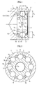
- Fig. 1 is a vertical cross-sectional view of a fixed-type constant velocity universal joint of the present invention taken along a plane that is parallel with an axial line.
- Fig. 2 is a horizontal cross-sectional view taken along a plane that is perpendicular to the axial line.
- Fig. 3 is a diagram of main sections in Fig. 2 .
- Main constituent elements of the fixed-type constant velocity universal joint of the present invention include an outer joint member 1, an inner joint member 2 provided within the outer joint member 1, eight torque transmitting balls 3 interposed between the outer joint member 1 and the inner joint member 2, and a cage 4 that holds the eight torque transmitting balls 3.
- the outer joint member 1 is connected to one of two shafts, a driving shaft and a driven shaft, that intersect with each other (not shown).
- An inner circumferential surface 1a of the outer joint member 1 is formed into a spherical shape.
- Eight guide grooves 1b that extend in an axial direction are formed on the spherical inner circumferential surface 1a, evenly spaced in the circumferential direction.
- the interior of the outer joint member I is filled with a lubricant. The lubricant is sealed from outside exposure by a bellows-shaped boot or the like attached to an opening end of the outer joint member 1 (not shown).
- An outer circumferential surface 2a of the inner joint member 2 is formed into a spherical shape.
- Eight guide grooves 2b that extend in the axial direction are formed on the spherical outer circumferential surface 2a, evenly spaced in the circumferential direction.
- a spline or a serration is formed on an inner circumferential surface 2c of the inner joint member 2 to allow the other of the two shafts (not shown) to be inserted and engaged.
- An outer circumferential surface 4a and an inner circumferential surface 4c of the cage 4 are both formed into a spherical shape.
- the cage 4 has eight pockets 4b formed such as to penetrate the cage 8, evenly spaced in the circumferential direction.
- the spherical inner circumferential surface 1a of the outer joint member 1, the spherical outer circumferential surface 2a of the inner joint member 2, and the outer circumferential surface 4a and the inner circumferential surface 4b of the cage 4 are all concentric spherical surfaces, the center of which is a joint center O. Spherical inner and outer circumferential surfaces that oppose each other are in spherical contact with each other.
- a torque transmitting ball 3 is housed in each pocket 4b of the cage 4.
- the torque transmitting balls 3 are disposed on ball tracks formed by each guide groove 1b of the outer joint member 1 and guide groove 2b of the inner joint member 2 opposing each other.
- a minimum surface roughness (arithmetic mean roughness) of the surface of the ball 3 is preferably set to Ra 0.03 ⁇ m.
- a maximum surface roughness is preferably set to Ra 0.6 ⁇ m.
- the minimum surface roughness of the ball 3 is more preferably Ra 0.05 ⁇ m.
- the maximum surface roughness is more preferably Ra 0.15 ⁇ m.
- a minimum percentage of a total area of the numerous miniscule recesses to a surface area of the ball 3 is preferably 10%.
- a maximum percentage is preferably 40%.
- a maximum parameter SK value of the surface roughness of the ball 3 is preferably set to -1.0.
- a minimum parameter SK value is preferably set to -4.9.
- the SK value refers to skewness of a distribution curve of the surface roughness.
- the SK value indicates relativity of an amplitude distribution curve of recesses and projections to an average line of surface roughness.
- the parameter SK value is positive when, in relation to the average line of the surface roughness, there are more peaks in the amplitude distribution curve.
- the parameter SK value is zero when, in relation to the average line of the surface roughness, the valleys and peaks in the amplitude distribution curve are equal.
- the parameter SK value is negative when, in relation to the average line of the surface roughness, there are more valleys in the amplitude distribution curve. Therefore, the parameter SK value of the surface roughness of the ball 3 on which the numerous miniscule recesses are formed is a negative value.
- the above-described numerical limits of the SK value and the surface roughness Ra of the surface of the ball 3, and the above-described numerical limits of the percentage of the total area of the numerous miniscule recesses serve as an effective range for forming a lubricant film layer on the surface of the ball 3.
- the roughness Ra, the SK value, and the percentage of the total area of the miniscule recesses are measured in six areas of the ball surface that are separated by about 90 degrees. Evaluation and judgment are performed using the mean values of the measurements. The above-mentioned effective range is also judged based on this method.
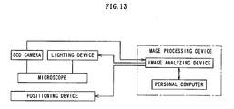
- Quantitative measurement of the miniscule recesses is performed by a device configuration shown in Fig. 13 . A method of reading the measurement is as follows.
- the ball is placed on a positioning device.
- the ball surface is magnified under a microscope.
- a charge-coupled device (CCD) camera loads an image into an image processing device that includes an image analyzing device and a personal computer. Analysis is performed with white portions of the image as flat surface areas, and black portions of the image as the recesses. With the black portions of the image as the recesses, size and distribution are calculated. A surface area percentage of the black portions is determined and evaluated. Details of a surface analysis method can be found in a method described in Japanese Patent Laid-open Publication No. 2001-183124 .
- the surface roughness and the SK value are measured by a measuring instrument Form Talysurf (manufactured by Taylor Hobson).
- a measuring instrument Form Talysurf manufactured by Taylor Hobson.
- cut-off type is Gaussian
- measurement length is 5 ⁇
- cut-off number is 6
- cut-off wavelength is 0.25mm
- measurement magnification is 10,000 times
- measurement speed is 0.30mm/s.
- a special barrel finishing treatment is known.
- surface processing can also be performed by shot-blast treatment and the like.
- Fig. 3 is a diagram of main sections in Fig. 2 . More specifically, Fig. 3 is a horizontal cross-sectional view of the opposing guide groove 1b of the outer joint member 1 and guide groove 2b of the inner joint member 2. As shown in Fig. 3 , the guide groove 1b of the outer joint member 1 and the guide groove 2b of the inner joint member 2 are both formed into Gothic arches. Therefore, the ball 3 comes into contact (angular contact) with the guide groove 1b of the outer joint member 1 at two points, C11 and C 12. The ball 3 also comes into contact (angular contact) with the guide groove 2b of the inner joint member 2 at two points, C21 and C22.
- Angles ⁇ formed by straight lines passing through the ball center O 3 , and each contact point C 11, C12, C21, and C22 and a straight line passing through the ball center O 3 and the joint center O are contact angles.
- the contact angle ⁇ of each contact point C11, C12, C21, and C22 is the same.
- a minimum contact angle ⁇ is preferably set to 30 degrees.
- a maximum contact angle ⁇ is preferably set to 38 degrees.
- the eight-ball joint according to the embodiment is formed having a smaller ball diameter than that of the conventional six-ball joint.
- the opposing guide grooves b and 2b are each formed into an arc shape.
- the respective center of curvatures O 1 and O 2 of the guide grooves 1b and 2b are at positions offset from the joint center O by an equal distance (F 10 and F 20 ) in opposite directions in the axial direction.
- the ball track formed by opposing guide grooves 1b and 2b is formed into a wedge shape that gradually widens towards one axial direction. In this instance, the ball track widens towards the opening end of the outer joint member 1.
- An angle formed by two tangential lines in the axial direction at the contact points (C11 and C22 or C 12 and C21) of the ball 3 in relation to the opposing guide grooves 1b and 2b is referred to as an angle of nip ⁇ 0 .
- the minimum angle of nip ⁇ 0 is preferably set to 8.5 degrees.
- the maximum angle of nip ⁇ 0 is preferably set to 12.5 degrees.
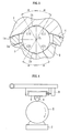
- a lubricant having a low coefficient of friction is preferably used as the lubricant.
- a lubricant having a maximum coefficient of friction of 0.07 measured using a Savan-type friction and wear tester, is preferred.
- the Savan-type friction and wear tester is configured by a 1/4-inch steel ball 6 pressed against a rotating ring 5 having a diameter of 40mm and a thickness of 4mm.
- the rotating ring 5 rotates at a peripheral speed of 108m/min, and a load of 12.7N is applied.
- the lubricant is supplied to the surface of the rotating ring 5 from the bottom end of the rotating ring 5 by a sponge 7.
- a load cell 9 detects movement of an air-slide 8 that holds the steel ball 6, and the coefficient of friction is measured.
- a specific example of the lubricant is urea grease.
- the consistency of the urea grease is preferably a minimum of No. 0 and a maximum of No. 2.
- Fig. 5 is a graph indicating a relationship between the coefficient of friction of the lubricant used in the fixed-type constant velocity universal joint and torque loss rate at this time, Four types of lubricants, each having a different coefficient of friction, were used. Torque loss was measured for each lubricant, under two sets of conditions: when input torque of the joint is small and rotation frequency is slow; and when input torque is large and rotation frequency is fast. Regarding symbols plotted on the graph, a circle indicates a lubricant with a coefficient of friction of about 0.1. Other symbols, such as a triangle, a square, and a diamond, indicate lubricants with a coefficient of friction of 0.07 or less. The graph in Fig. 5 clearly indicates that when a lubricant having a coefficient of friction of 0.07 or less is used, the torque loss rate decreases compared to when the lubricant having the coefficient of friction of about 0.1 is used. In other words, torque transmission efficiency improves.
- Fig. 6 is a graph comparing torque loss rates between a joint having a ball with a surface on which numerous miniscule recesses are formed (the joint of the present invention) and a joint having a ball with no miniscule recesses (a comparison example joint).
- the torque loss rate was measured for each joint, under two sets of conditions: when input torque of the joint is small and rotation frequency is slow; and when input torque is large and rotation frequency is fast.
- the joint of the present invention and the comparison example joint were both filled with a lubricant having the same coefficient of friction.
- a circle shown on the graph in Fig. 6 indicates test data of the joint of the present invention.
- a diamond indicates test data of the comparison example joint.
- a dashed line indicates an average line of each piece of data of the present invention.
- a dotted line indicates an average line of each piece of data of the comparison example. The difference between the two average lines clearly indicates that the torque loss rate is reduced in the present invention, compared to the comparison example. Torque transmission efficiency is improved.
- Fig. 7 is a graph indicating the respective torque loss rates of a joint (the joint of the present invention) using a lubricant having a coefficient of friction that is 0.07 or less and having a ball on which numerous miniscule recesses are formed, and a joint (a comparison example joint) using a lubricant having a coefficient of friction that is about 0.1 and having a ball on which no miniscule recesses are formed.
- the torque loss rate was measured under two sets of conditions: when input torque of the joint is small and rotation frequency is slow; and when input torque is large and rotation frequency is fast.
- a circle indicates data of the comparison example.
- a triangle indicates data of the present invention.
- a diamond indicates a predicted value obtained when the test result of the present invention was predicted based on the test results in Fig. 5 and Fig. 6 .
- the results in Fig. 7 clearly indicate that the torque loss rate is reduced in the present invention, compared to the comparison example.
- an actual measurement value (triangle) of when a lubricant having a low coefficient of friction (coefficient of friction of 0.07 or less) and a ball on which numerous miniscule recesses are formed are used in combination shows a lower torque loss rate than the predicted measurement value (diamond) estimated from results of when a lubricant having a low coefficient of friction (coefficient of friction of 0.07 or less) and a ball on which numerous miniscule recesses are formed are used individually. It is clear that the advantageous effect on torque transmission efficiency is further enhanced by combined use of both the lubricant having a low coefficient of friction (coefficient of friction of 0.07 or less) and the ball on which the numerous miniscule recesses are formed.
Landscapes
- Engineering & Computer Science (AREA)
- General Engineering & Computer Science (AREA)
- Mechanical Engineering (AREA)
- Rolling Contact Bearings (AREA)
- Pivots And Pivotal Connections (AREA)
Claims (5)
- Gleichlauf- Universalgelenk vom feststehenden Typ, enthaltend ein äußeres Gelenkteil (1), das mit einem Schmiermittel gefüllt ist und auf dem eine Führungsnut (1 b), die sich in einer axialer Richtung erstreckt, auf einer kugelförmigen inneren Umfangsoberfläche (1a) gebildet ist, ein inneres Gelenkteil (2), vorgesehen auf einer Innendurchmesserseite des äußeren Gelenkteils (1), und in dem eine Führungsnut (2b) die sich in axialer Richtung erstreckt, auf einer kugelförmigen äußeren Umfangsoberfläche (2a) gebildet ist, eine Drehmomentübertragungskugel (3), eingesetzt zwischen gegenüberliegende Führungsnuten (1 b, 2b) des äußeren Gelenkteils (1) und des inneren Gelenkteils (2), um frei zu rollen, und einen Käfig (4), der jede Kugel (3) hält, dadurch gekennzeichnet, dass
zahlreiche winzige Aussparungen zufallverteilt auf einer Oberfläche der Kugel (3) gebildet sind und ein maximaler Reibungskoeffizient des Schmiermittels 0,07 beträgt,
eine minimale Oberflächenrauhigkeit der Kugel, auf der zahlreiche winzige Aussparungen gebildet sind, auf Ra 0,03 µm festgesetzt ist, eine maximale Oberflächenrauhigkeit auf Ra 0,6 µm festgesetzt ist,
ein maximaler SK- Parameterwert der Oberflächenrauhigkeit der Kugel auf -1,0 festgesetzt ist, wobei der SK- Wert wie folgt definiert ist:SK = ∫ (x-x0)3 · P(x) dx/σ3, wo x eine Höhe der Rauigkeit anzeigt, x0 eine Durchschnittshöhe der Rauigkeit anzeigt, P(x) eine Wahrscheinlichkeitsdichtefunktion der Amplitude der Rauigkeit anzeigt, und σ eine mittlere quadratische Rauigkeit anzeigt, wobei ein minimaler Prozentsatz einer gesamten Fläche der zahlreichen winzigen Aussparungen zu einer Oberflächenfläche der Kugel auf 10% festgesetzt ist, und ein minimaler Prozentsatz der gesamten Fläche der zahlreichen winzigen Aussparungen zu der Oberflächenfläche der Kugel auf 40% festgesetzt ist. - Gleichlauf- Universalgelenk vom feststehenden Typ nach Anspruch 1, wobei das Schmiermittel Harnstoffschmierfett ist, wobei eine minimale Konsistenz des Harnstoffschmierfettes Nr. 0 und eine maximale Konsistenz Nr. 2 ist.
- Gleichlauf- Universalgelenk vom feststehenden Typ nach Anspruch 1 oder 2, wobei eine minimale Oberflächenrauhigkeit der Kugel (3), auf der die zahlreichen winzigen Aussparungen gebildet sind, auf Ra 0,05 µm festgesetzt ist, eine maximale Oberflächenrauhigkeit auf Ra 0,15 µm festgesetzt ist, ein minimaler SK- Parameterwert auf -4,9 festgesetzt ist und ein maximaler SK- Parameterwert der Oberflächenrauhigkeit der Kugel (3) auf -1,0 festgesetzt ist.
- Gleichlauf- Universalgelenk vom feststehenden Typ nach einem der Ansprüche 1 bis 3, wobei acht Führungsnuten (1 b, 2b) jeweils auf dem äußeren Gelenkteil (1) und dem inneren Gelenkteil (2) gebildet sind, acht Drehmomentübertragungskugeln (3) jeweils zwischen gegenüberliegende Führungsnuten (1 b, 2b) des äußeren Gelenkteils und des inneren Gelenkteils (2) eingesetzt sind, um frei zu rollen, und die Kugel (3) in Winkelkontakt an jeweils zwei Punkten mit der Führungsnut (1 b) des äußeren Gelenkteils (1) und der Führungsnut (2b) des inneren Gelenkteils (2) ist.
- Gleichlauf- Universalgelenk vom feststehenden Typ nach Anspruch 4, wobei ein minimaler Kontaktwinkel auf 30 Grad festgesetzt ist und ein maximaler Kontaktwinkel auf 38 festgesetzt ist, wobei der Kontaktwinkel gebildet ist durch eine gerade Linie, die durch einen Kontaktpunkt zwischen der Kugel (3) und der Führungsnut (1 b) des äußeren Gelenkteils (1) und der Führungsnut (2b) des inneren Gelenkteils (2) hindurchgeht, und einer Kugelmitte, und eine gerade Linie, die durch die Kugelmitte und ein Gelenkmitte hindurchgeht, und wobei ein minimaler Bisswinkel auf 8,5 Grad und ein maximaler Bisswinkel auf 12,5 Grad festgesetzt ist, wobei der Bisswinkel durch zwei tangentiale Linien in der axialen Richtung an jedem Kontaktpunkt zwischen den gegenüberliegenden Führungsnuten (1 b, 2b) des äußeren Gelenkteils (1) und des inneren Gelenkteils (2) und die Kugel (3) gebildet ist.
Applications Claiming Priority (2)
| Application Number | Priority Date | Filing Date | Title |
|---|---|---|---|
| JP2007024426A JP5128139B2 (ja) | 2007-02-02 | 2007-02-02 | 固定式等速自在継手 |
| PCT/JP2008/050047 WO2008096558A1 (ja) | 2007-02-02 | 2008-01-07 | 固定式等速自在継手 |
Publications (3)
| Publication Number | Publication Date |
|---|---|
| EP2119930A1 EP2119930A1 (de) | 2009-11-18 |
| EP2119930A4 EP2119930A4 (de) | 2012-04-25 |
| EP2119930B1 true EP2119930B1 (de) | 2013-06-19 |
Family
ID=39681469
Family Applications (1)
| Application Number | Title | Priority Date | Filing Date |
|---|---|---|---|
| EP08702928.6A Not-in-force EP2119930B1 (de) | 2007-02-02 | 2008-01-07 | Festgleichlauf-kreuzgelenk |
Country Status (4)
| Country | Link |
|---|---|
| US (1) | US8172689B2 (de) |
| EP (1) | EP2119930B1 (de) |
| JP (1) | JP5128139B2 (de) |
| WO (1) | WO2008096558A1 (de) |
Families Citing this family (6)
| Publication number | Priority date | Publication date | Assignee | Title |
|---|---|---|---|---|
| JP5236196B2 (ja) * | 2007-03-27 | 2013-07-17 | Ntn株式会社 | 摺動式等速自在継手 |
| DE102009011262B4 (de) * | 2009-03-02 | 2021-10-28 | Volkswagen Ag | Gleichlauffestgelenk |
| BRPI1001172A2 (pt) * | 2009-03-13 | 2015-08-18 | Gm Global Tech Operations Inc | Junta de velocidade constante e método de fabricar uma junta de velocidade constante |
| JP5399203B2 (ja) * | 2009-10-22 | 2014-01-29 | Ntn株式会社 | 固定型等速自在継手 |
| JP6199159B2 (ja) * | 2013-11-05 | 2017-09-20 | Ntn株式会社 | 固定式等速自在継手 |
| CN104806650B (zh) * | 2014-03-18 | 2017-11-21 | 万向钱潮股份有限公司 | 一种固定端等速万向节 |
Family Cites Families (11)
| Publication number | Priority date | Publication date | Assignee | Title |
|---|---|---|---|---|
| JPH08128454A (ja) * | 1994-11-02 | 1996-05-21 | Toyoda Mach Works Ltd | 等速ジョイント |
| JP3460107B2 (ja) | 1996-05-28 | 2003-10-27 | Ntn株式会社 | 等速自在継手 |
| JP3859267B2 (ja) | 1996-05-28 | 2006-12-20 | Ntn株式会社 | 固定型等速自在継手 |
| JP4100846B2 (ja) | 1999-12-24 | 2008-06-11 | Ntn株式会社 | 表面性状検査方法および表面性状検査装置 |
| JP2002188653A (ja) * | 2000-12-20 | 2002-07-05 | Ntn Corp | 等速自在継手 |
| US20030017877A1 (en) * | 2001-04-24 | 2003-01-23 | Masazumi Kobayashi | Constant velocity universal joint |
| US6736729B2 (en) * | 2002-07-03 | 2004-05-18 | Gkn Automotive, Inc. | Constant velocity joint and method of making same |
| JP4272930B2 (ja) * | 2003-06-18 | 2009-06-03 | 昭和シェル石油株式会社 | 等速ジョイント用ウレアグリース組成物 |
| JP2006258207A (ja) * | 2005-03-17 | 2006-09-28 | Ntn Corp | 固定式等速自在継手 |
| JP2006283830A (ja) * | 2005-03-31 | 2006-10-19 | Ntn Corp | 等速自在継手 |
| JP2007016851A (ja) * | 2005-07-06 | 2007-01-25 | Ntn Corp | トリポード型等速自在継手 |
-
2007
- 2007-02-02 JP JP2007024426A patent/JP5128139B2/ja not_active Expired - Fee Related
-
2008
- 2008-01-07 EP EP08702928.6A patent/EP2119930B1/de not_active Not-in-force
- 2008-01-07 US US12/523,094 patent/US8172689B2/en not_active Expired - Fee Related
- 2008-01-07 WO PCT/JP2008/050047 patent/WO2008096558A1/ja not_active Ceased
Also Published As
| Publication number | Publication date |
|---|---|
| EP2119930A1 (de) | 2009-11-18 |
| US8172689B2 (en) | 2012-05-08 |
| US20100099504A1 (en) | 2010-04-22 |
| EP2119930A4 (de) | 2012-04-25 |
| JP2008190596A (ja) | 2008-08-21 |
| JP5128139B2 (ja) | 2013-01-23 |
| WO2008096558A1 (ja) | 2008-08-14 |
Similar Documents
| Publication | Publication Date | Title |
|---|---|---|
| EP2119931B1 (de) | Universelles gleichlauffestgelenk | |
| EP2119930B1 (de) | Festgleichlauf-kreuzgelenk | |
| JP5101430B2 (ja) | 固定式等速自在継手 | |
| JP3859295B2 (ja) | 摺動型等速自在継手 | |
| EP0861992B1 (de) | Homokinetisches Kreuzgelenk | |
| US20110065519A1 (en) | Fixed uniform-motion universal joint | |
| EP2042764A1 (de) | Homokinetisches kreuzgelenk | |
| EP2299134B1 (de) | Festgelegtes gleichlaufgelenk | |
| CN100529450C (zh) | 固定式等速万向接头 | |
| EP1260723B1 (de) | Wälzlager mit strichförmigen Schleifspuren auf den Walzenendflächen und auf die Flanschfürungsfläche | |
| CN101835999B (zh) | 固定式等速万向接头 | |
| EP1505308B1 (de) | Gleichlaufgelenk | |
| EP1697649B1 (de) | Homokinetisches kreuzgelenk | |
| JP2005201371A (ja) | 等速ジョイント | |
| WO2015071877A1 (en) | Improved torque-transmitting joint and joint components, methods of manufacturing, and methods of inspection | |
| EP1915551B1 (de) | Reibantriebsvorrichtung | |
| JP2012193860A (ja) | 固定式等速自在継手 | |
| EP2594820A1 (de) | Gleichlauf-kugelgelenk | |
| US20100087262A1 (en) | Plunging type constant velocity universal joint | |
| JP2021188742A (ja) | トリポード型等速自在継手 | |
| US10520015B2 (en) | Rolling bearing and rotating device including rolling bearing | |
| JP2009079684A (ja) | 固定式等速自在継手 | |
| US12460680B2 (en) | Tripod type constant velocity universal joint | |
| CN120608927A (zh) | 滑动式等速万向联轴器 | |
| JPS646413Y2 (de) |
Legal Events
| Date | Code | Title | Description |
|---|---|---|---|
| PUAI | Public reference made under article 153(3) epc to a published international application that has entered the european phase |
Free format text: ORIGINAL CODE: 0009012 |
|
| 17P | Request for examination filed |
Effective date: 20090811 |
|
| AK | Designated contracting states |
Kind code of ref document: A1 Designated state(s): AT BE BG CH CY CZ DE DK EE ES FI FR GB GR HR HU IE IS IT LI LT LU LV MC MT NL NO PL PT RO SE SI SK TR |
|
| DAX | Request for extension of the european patent (deleted) | ||
| A4 | Supplementary search report drawn up and despatched |
Effective date: 20120323 |
|
| RIC1 | Information provided on ipc code assigned before grant |
Ipc: F16D 3/20 20060101AFI20120319BHEP Ipc: F16D 3/223 20110101ALI20120319BHEP Ipc: F16D 3/224 20110101ALI20120319BHEP |
|
| GRAP | Despatch of communication of intention to grant a patent |
Free format text: ORIGINAL CODE: EPIDOSNIGR1 |
|
| GRAS | Grant fee paid |
Free format text: ORIGINAL CODE: EPIDOSNIGR3 |
|
| GRAA | (expected) grant |
Free format text: ORIGINAL CODE: 0009210 |
|
| AK | Designated contracting states |
Kind code of ref document: B1 Designated state(s): AT BE BG CH CY CZ DE DK EE ES FI FR GB GR HR HU IE IS IT LI LT LU LV MC MT NL NO PL PT RO SE SI SK TR |
|
| REG | Reference to a national code |
Ref country code: GB Ref legal event code: FG4D |
|
| REG | Reference to a national code |
Ref country code: CH Ref legal event code: EP |
|
| REG | Reference to a national code |
Ref country code: AT Ref legal event code: REF Ref document number: 617819 Country of ref document: AT Kind code of ref document: T Effective date: 20130715 |
|
| REG | Reference to a national code |
Ref country code: IE Ref legal event code: FG4D |
|
| REG | Reference to a national code |
Ref country code: DE Ref legal event code: R096 Ref document number: 602008025412 Country of ref document: DE Effective date: 20130814 |
|
| PG25 | Lapsed in a contracting state [announced via postgrant information from national office to epo] |
Ref country code: SI Free format text: LAPSE BECAUSE OF FAILURE TO SUBMIT A TRANSLATION OF THE DESCRIPTION OR TO PAY THE FEE WITHIN THE PRESCRIBED TIME-LIMIT Effective date: 20130619 Ref country code: LT Free format text: LAPSE BECAUSE OF FAILURE TO SUBMIT A TRANSLATION OF THE DESCRIPTION OR TO PAY THE FEE WITHIN THE PRESCRIBED TIME-LIMIT Effective date: 20130619 Ref country code: ES Free format text: LAPSE BECAUSE OF FAILURE TO SUBMIT A TRANSLATION OF THE DESCRIPTION OR TO PAY THE FEE WITHIN THE PRESCRIBED TIME-LIMIT Effective date: 20130930 Ref country code: FI Free format text: LAPSE BECAUSE OF FAILURE TO SUBMIT A TRANSLATION OF THE DESCRIPTION OR TO PAY THE FEE WITHIN THE PRESCRIBED TIME-LIMIT Effective date: 20130619 Ref country code: SE Free format text: LAPSE BECAUSE OF FAILURE TO SUBMIT A TRANSLATION OF THE DESCRIPTION OR TO PAY THE FEE WITHIN THE PRESCRIBED TIME-LIMIT Effective date: 20130619 Ref country code: NO Free format text: LAPSE BECAUSE OF FAILURE TO SUBMIT A TRANSLATION OF THE DESCRIPTION OR TO PAY THE FEE WITHIN THE PRESCRIBED TIME-LIMIT Effective date: 20130919 Ref country code: GR Free format text: LAPSE BECAUSE OF FAILURE TO SUBMIT A TRANSLATION OF THE DESCRIPTION OR TO PAY THE FEE WITHIN THE PRESCRIBED TIME-LIMIT Effective date: 20130920 |
|
| REG | Reference to a national code |
Ref country code: AT Ref legal event code: MK05 Ref document number: 617819 Country of ref document: AT Kind code of ref document: T Effective date: 20130619 |
|
| REG | Reference to a national code |
Ref country code: LT Ref legal event code: MG4D |
|
| PG25 | Lapsed in a contracting state [announced via postgrant information from national office to epo] |
Ref country code: BG Free format text: LAPSE BECAUSE OF FAILURE TO SUBMIT A TRANSLATION OF THE DESCRIPTION OR TO PAY THE FEE WITHIN THE PRESCRIBED TIME-LIMIT Effective date: 20130919 Ref country code: HR Free format text: LAPSE BECAUSE OF FAILURE TO SUBMIT A TRANSLATION OF THE DESCRIPTION OR TO PAY THE FEE WITHIN THE PRESCRIBED TIME-LIMIT Effective date: 20130619 |
|
| REG | Reference to a national code |
Ref country code: NL Ref legal event code: VDEP Effective date: 20130619 |
|
| PG25 | Lapsed in a contracting state [announced via postgrant information from national office to epo] |
Ref country code: LV Free format text: LAPSE BECAUSE OF FAILURE TO SUBMIT A TRANSLATION OF THE DESCRIPTION OR TO PAY THE FEE WITHIN THE PRESCRIBED TIME-LIMIT Effective date: 20130619 |
|
| PG25 | Lapsed in a contracting state [announced via postgrant information from national office to epo] |
Ref country code: IS Free format text: LAPSE BECAUSE OF FAILURE TO SUBMIT A TRANSLATION OF THE DESCRIPTION OR TO PAY THE FEE WITHIN THE PRESCRIBED TIME-LIMIT Effective date: 20131019 Ref country code: EE Free format text: LAPSE BECAUSE OF FAILURE TO SUBMIT A TRANSLATION OF THE DESCRIPTION OR TO PAY THE FEE WITHIN THE PRESCRIBED TIME-LIMIT Effective date: 20130619 Ref country code: AT Free format text: LAPSE BECAUSE OF FAILURE TO SUBMIT A TRANSLATION OF THE DESCRIPTION OR TO PAY THE FEE WITHIN THE PRESCRIBED TIME-LIMIT Effective date: 20130619 Ref country code: CY Free format text: LAPSE BECAUSE OF FAILURE TO SUBMIT A TRANSLATION OF THE DESCRIPTION OR TO PAY THE FEE WITHIN THE PRESCRIBED TIME-LIMIT Effective date: 20130814 Ref country code: BE Free format text: LAPSE BECAUSE OF FAILURE TO SUBMIT A TRANSLATION OF THE DESCRIPTION OR TO PAY THE FEE WITHIN THE PRESCRIBED TIME-LIMIT Effective date: 20130619 Ref country code: PT Free format text: LAPSE BECAUSE OF FAILURE TO SUBMIT A TRANSLATION OF THE DESCRIPTION OR TO PAY THE FEE WITHIN THE PRESCRIBED TIME-LIMIT Effective date: 20131021 Ref country code: CZ Free format text: LAPSE BECAUSE OF FAILURE TO SUBMIT A TRANSLATION OF THE DESCRIPTION OR TO PAY THE FEE WITHIN THE PRESCRIBED TIME-LIMIT Effective date: 20130619 Ref country code: SK Free format text: LAPSE BECAUSE OF FAILURE TO SUBMIT A TRANSLATION OF THE DESCRIPTION OR TO PAY THE FEE WITHIN THE PRESCRIBED TIME-LIMIT Effective date: 20130619 |
|
| PG25 | Lapsed in a contracting state [announced via postgrant information from national office to epo] |
Ref country code: RO Free format text: LAPSE BECAUSE OF FAILURE TO SUBMIT A TRANSLATION OF THE DESCRIPTION OR TO PAY THE FEE WITHIN THE PRESCRIBED TIME-LIMIT Effective date: 20130619 Ref country code: NL Free format text: LAPSE BECAUSE OF FAILURE TO SUBMIT A TRANSLATION OF THE DESCRIPTION OR TO PAY THE FEE WITHIN THE PRESCRIBED TIME-LIMIT Effective date: 20130619 Ref country code: PL Free format text: LAPSE BECAUSE OF FAILURE TO SUBMIT A TRANSLATION OF THE DESCRIPTION OR TO PAY THE FEE WITHIN THE PRESCRIBED TIME-LIMIT Effective date: 20130619 |
|
| PG25 | Lapsed in a contracting state [announced via postgrant information from national office to epo] |
Ref country code: CY Free format text: LAPSE BECAUSE OF FAILURE TO SUBMIT A TRANSLATION OF THE DESCRIPTION OR TO PAY THE FEE WITHIN THE PRESCRIBED TIME-LIMIT Effective date: 20130619 |
|
| PLBE | No opposition filed within time limit |
Free format text: ORIGINAL CODE: 0009261 |
|
| STAA | Information on the status of an ep patent application or granted ep patent |
Free format text: STATUS: NO OPPOSITION FILED WITHIN TIME LIMIT |
|
| PG25 | Lapsed in a contracting state [announced via postgrant information from national office to epo] |
Ref country code: DK Free format text: LAPSE BECAUSE OF FAILURE TO SUBMIT A TRANSLATION OF THE DESCRIPTION OR TO PAY THE FEE WITHIN THE PRESCRIBED TIME-LIMIT Effective date: 20130619 |
|
| 26N | No opposition filed |
Effective date: 20140320 |
|
| PG25 | Lapsed in a contracting state [announced via postgrant information from national office to epo] |
Ref country code: IT Free format text: LAPSE BECAUSE OF FAILURE TO SUBMIT A TRANSLATION OF THE DESCRIPTION OR TO PAY THE FEE WITHIN THE PRESCRIBED TIME-LIMIT Effective date: 20130619 |
|
| REG | Reference to a national code |
Ref country code: DE Ref legal event code: R097 Ref document number: 602008025412 Country of ref document: DE Effective date: 20140320 |
|
| PG25 | Lapsed in a contracting state [announced via postgrant information from national office to epo] |
Ref country code: MC Free format text: LAPSE BECAUSE OF FAILURE TO SUBMIT A TRANSLATION OF THE DESCRIPTION OR TO PAY THE FEE WITHIN THE PRESCRIBED TIME-LIMIT Effective date: 20130619 Ref country code: LU Free format text: LAPSE BECAUSE OF FAILURE TO SUBMIT A TRANSLATION OF THE DESCRIPTION OR TO PAY THE FEE WITHIN THE PRESCRIBED TIME-LIMIT Effective date: 20140107 |
|
| REG | Reference to a national code |
Ref country code: CH Ref legal event code: PL |
|
| GBPC | Gb: european patent ceased through non-payment of renewal fee |
Effective date: 20140107 |
|
| PG25 | Lapsed in a contracting state [announced via postgrant information from national office to epo] |
Ref country code: LI Free format text: LAPSE BECAUSE OF NON-PAYMENT OF DUE FEES Effective date: 20140131 Ref country code: CH Free format text: LAPSE BECAUSE OF NON-PAYMENT OF DUE FEES Effective date: 20140131 |
|
| REG | Reference to a national code |
Ref country code: IE Ref legal event code: MM4A |
|
| PG25 | Lapsed in a contracting state [announced via postgrant information from national office to epo] |
Ref country code: GB Free format text: LAPSE BECAUSE OF NON-PAYMENT OF DUE FEES Effective date: 20140107 |
|
| PG25 | Lapsed in a contracting state [announced via postgrant information from national office to epo] |
Ref country code: IE Free format text: LAPSE BECAUSE OF NON-PAYMENT OF DUE FEES Effective date: 20140107 |
|
| REG | Reference to a national code |
Ref country code: FR Ref legal event code: PLFP Year of fee payment: 9 |
|
| PG25 | Lapsed in a contracting state [announced via postgrant information from national office to epo] |
Ref country code: MT Free format text: LAPSE BECAUSE OF FAILURE TO SUBMIT A TRANSLATION OF THE DESCRIPTION OR TO PAY THE FEE WITHIN THE PRESCRIBED TIME-LIMIT Effective date: 20130619 |
|
| PG25 | Lapsed in a contracting state [announced via postgrant information from national office to epo] |
Ref country code: TR Free format text: LAPSE BECAUSE OF FAILURE TO SUBMIT A TRANSLATION OF THE DESCRIPTION OR TO PAY THE FEE WITHIN THE PRESCRIBED TIME-LIMIT Effective date: 20130619 Ref country code: HU Free format text: LAPSE BECAUSE OF FAILURE TO SUBMIT A TRANSLATION OF THE DESCRIPTION OR TO PAY THE FEE WITHIN THE PRESCRIBED TIME-LIMIT; INVALID AB INITIO Effective date: 20080107 |
|
| REG | Reference to a national code |
Ref country code: FR Ref legal event code: PLFP Year of fee payment: 10 |
|
| REG | Reference to a national code |
Ref country code: FR Ref legal event code: PLFP Year of fee payment: 11 |
|
| PGFP | Annual fee paid to national office [announced via postgrant information from national office to epo] |
Ref country code: FR Payment date: 20181213 Year of fee payment: 12 |
|
| PGFP | Annual fee paid to national office [announced via postgrant information from national office to epo] |
Ref country code: DE Payment date: 20181228 Year of fee payment: 12 |
|
| REG | Reference to a national code |
Ref country code: DE Ref legal event code: R119 Ref document number: 602008025412 Country of ref document: DE |
|
| PG25 | Lapsed in a contracting state [announced via postgrant information from national office to epo] |
Ref country code: DE Free format text: LAPSE BECAUSE OF NON-PAYMENT OF DUE FEES Effective date: 20200801 Ref country code: FR Free format text: LAPSE BECAUSE OF NON-PAYMENT OF DUE FEES Effective date: 20200131 |