EP2119951A2 - Dispositif d'alimentation en lubrifiant - Google Patents
Dispositif d'alimentation en lubrifiant Download PDFInfo
- Publication number
- EP2119951A2 EP2119951A2 EP09005883A EP09005883A EP2119951A2 EP 2119951 A2 EP2119951 A2 EP 2119951A2 EP 09005883 A EP09005883 A EP 09005883A EP 09005883 A EP09005883 A EP 09005883A EP 2119951 A2 EP2119951 A2 EP 2119951A2
- Authority
- EP
- European Patent Office
- Prior art keywords
- lubricant
- pump
- supply device
- lubricant supply
- shaft
- Prior art date
- Legal status (The legal status is an assumption and is not a legal conclusion. Google has not performed a legal analysis and makes no representation as to the accuracy of the status listed.)
- Withdrawn
Links
Images




Classifications
-
- F—MECHANICAL ENGINEERING; LIGHTING; HEATING; WEAPONS; BLASTING
- F16—ENGINEERING ELEMENTS AND UNITS; GENERAL MEASURES FOR PRODUCING AND MAINTAINING EFFECTIVE FUNCTIONING OF MACHINES OR INSTALLATIONS; THERMAL INSULATION IN GENERAL
- F16N—LUBRICATING
- F16N11/00—Arrangements for supplying grease from a stationary reservoir or the equivalent in or on the machine or member to be lubricated; Grease cups
- F16N11/08—Arrangements for supplying grease from a stationary reservoir or the equivalent in or on the machine or member to be lubricated; Grease cups with mechanical drive, other than directly by springs or weights
-
- F—MECHANICAL ENGINEERING; LIGHTING; HEATING; WEAPONS; BLASTING
- F16—ENGINEERING ELEMENTS AND UNITS; GENERAL MEASURES FOR PRODUCING AND MAINTAINING EFFECTIVE FUNCTIONING OF MACHINES OR INSTALLATIONS; THERMAL INSULATION IN GENERAL
- F16N—LUBRICATING
- F16N13/00—Lubricating-pumps
-
- F—MECHANICAL ENGINEERING; LIGHTING; HEATING; WEAPONS; BLASTING
- F16—ENGINEERING ELEMENTS AND UNITS; GENERAL MEASURES FOR PRODUCING AND MAINTAINING EFFECTIVE FUNCTIONING OF MACHINES OR INSTALLATIONS; THERMAL INSULATION IN GENERAL
- F16N—LUBRICATING
- F16N7/00—Arrangements for supplying oil or unspecified lubricant from a stationary reservoir or the equivalent in or on the machine or member to be lubricated
- F16N7/14—Arrangements for supplying oil or unspecified lubricant from a stationary reservoir or the equivalent in or on the machine or member to be lubricated the lubricant being conveyed from the reservoir by mechanical means
- F16N7/16—Arrangements for supplying oil or unspecified lubricant from a stationary reservoir or the equivalent in or on the machine or member to be lubricated the lubricant being conveyed from the reservoir by mechanical means the oil being carried up by a lifting device
Definitions
- the invention relates to a lubricant supply device having a lubricant reservoir, in the bottom region of which is a lubricant driven by a motor, the transport element delivering the lubricant to a pump which delivers the lubricant under increased pressure to a lubricant line.
- a device of this kind is for example from the EP 0 009 908 B1 known.
- a device for pumping a lubricant is described in which from a container by means of a screw conveyor, the medium to be delivered is moved into the region of a pump, which then brings it to a desired pressure.
- the auger and the pump each have separate drives.
- the invention is therefore based on the object , a device of the type mentioned in such a way that with only a single drive, the conveying of the lubricant and the pressurization of the same can take place, with a simple construction with a compact design is possible.
- Another essential objective is that a modular design of the device is to be achieved, which in particular makes it possible to carry out a simple assembly and maintenance with easy replacement of components.
- the solution of this object by the invention is characterized in that the conveying element comprises a shaft driven by the motor, around which extend funding, wherein the one axial end of the shaft rotatably connected to a shaft portion of the pump, so that the motor both can drive the conveyor element as well as the pump.
- the conveying element is designed as a screw conveyor, in which a conveying means in the form of at least one helix extends around the shaft.
- the shaft may extend beyond the axial extent of the at least one flight.
- the shaft and the shaft part of the pump are particularly preferably arranged coaxially with each other and non-rotatably connected to each other via a positive connection.
- the positive connection is the only connection between the shaft and the shaft part of the pump.
- the pump is preferably designed as a radial piston pump with at least one radial piston unit. It can also be arranged a plurality of radial piston units around the circumference of the shaft part of the pump. Particularly preferred between 2 and 10 radial piston units arranged equidistant around the circumference of the shaft portion of the pump. All radial piston units can be driven by an eccentric, which is rotatably connected to the shaft part of the pump. Furthermore, it can be provided that all radial piston units are biased with a spring element so that they occupy a defined position without external force. Alternatively, however, it is also possible to provide positive guidance of the pistons.
- the motor can be driven electrically, hydraulically or pneumatically.
- the lubricant line preferably comprises a ring line, which is supplied by all radial piston units with pressurized lubricant. Between a radial piston unit and the ring line, a check valve may be arranged.
- the ring line can be connected to a pressure relief valve.
- the ring line is connected according to a preferred embodiment of the invention with at least one directional control valve.
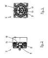
- a lubricant supply device 1 can be seen, with the grease or oil can be promoted as a lubricant.
- the device 1 is characterized a modular design and can be designed for different lubrication systems, in particular for a two-line centralized lubrication system, for a single-line centralized lubrication system or for a progressive lubrication system.
- the device 1 has a receptacle 2 for lubricant (oil or grease) and is preferably made cylindrical; but it is also possible a square basic shape.
- a motor 3 drives the shaft 7 of a conveyor element 4 in the form of a screw conveyor.
- a worm gear 8, which acts as a conveyor, extends helically around the shaft 7 in a known manner and promotes the rotation of the shaft 7 lubricant.
- a pump 5 is arranged in the form of a radial piston pump.
- the pump 5 has a shaft part 9, which is rotatably coupled to the shaft 7.
- the rotationally fixed connection 16 (s. Fig. 1 ) carried out so that the torque is transmitted from the shaft 7 to the shaft part 9 exclusively by a positive coupling.
- the positive connection 16 can be a radially extending groove 17 (eg in the shaft part 9) into which a congruently shaped projection (eg in the shaft) engages.
- the connection 16 works alone on a positive basis.
- the pump 5 is designed as a radial piston pump, ie, there are several radial piston units 10 equidistant around the circumference of the shaft part 9 of the pump 5 around which are actuated by an eccentric 11 which is rotatably connected to the shaft part 9 of the pump 5.
- the pump 5 is equipped with a plurality of pump elements in the form of the radial piston units 10, wherein the piston stroke movement is caused by the rotating eccentric 11.
- the piston return (suction phase) can be done by compression springs or positively driven.
- Each radial piston unit conveys the medium via a check valve 13 in a ring line 12 (s. FIGS. 4 to 10 ).
- a protection of the lubricant line 6 against overpressure takes place by a pressure relief valve 14th
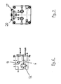
- Fig. 4 is out of the ring line 12 per a pressure line to 3/2-way valve connections of a directional control valve 15 out (port “A” in Fig. 4/5 ).
- the valve connections "B” in Fig. 4/5 lead to a container (T).
- Valve connections "C” lead to a pump outlet A / P or B / P.
- Other pump connections are the manometer connections MA and MB and a measuring port M or a vent.
- Fig. 4/5 is a Zweitechnischszentralschmiersystem with two reversing valves in the form of two 3/2-way valves provided.
- the valve 18 is switched, the promotion takes place at output A / P.
- valve 19 is not switched, the output B / R connects to tank T (depressurised).
- the valve 19 is switched, the promotion takes place at output B / R.
- the valve 18 is not switched, the output A / P connects to the tank T (depressurized).
- the valves must be switched alternately for this application (delivery at A / P leads to B / R without pressure in container, delivery at B / R leads to A / P without pressure in container).
- Fig. 6/7 is a two-line centralized lubrication system without attached 3/2-way valves shown. Instead of two valves here two baffles 20 and 21 are provided. A Zweitechnischtechnischtechnisch must be installed separately after the pump 5 in the two main lines. Port A / P is the pressure port for the fluid being pumped, port B / R is the port port for pressure relief.
- Fig. 8/9 is a single-line centralized lubrication system with a mounted 3/2-way valve shown. If the valve 18 is switched, the promotion takes place at output A / P. When valve 18 is not switched, output A / P is connected to tank T (depressurized). The valve connections of the valve 19 from Fig. 5 are in the solution according to Fig. 9 closed with a closure plate 22. The output B / R is closed.
- Fig. 10/11 is a centralized lubrication system without attached 3/2-way valves provided.
- a baffle 23 At the connection for the valve 18 according to Fig. 5 is in the solution according to Fig. 11 a baffle 23 and the connection for the valve 19 according to Fig. 5 a closure plate 24 is provided. The entire promotion takes place at exit A / P. The connection B / R is closed.
- the motor 3 is a geared motor with in particular electric, hydraulic or pneumatic drive.
- the screw conveyor 4 promotes by the rotation of the motor 3 medium to the pump 5 and drives these at the same time.
- the receptacle 2 is preferably designed in container sizes for receiving 15, 30 or 60 kg of lubricant.
- the proposed invention is characterized in that the arrangement of motor, screw conveyor and pump is modular. These elements are preferably coupled only form-fitting, ie they are plugged together and not positively connected to each other. This allows easy disassembly or a simple exchange of pump and motor without disassembly of the other components. This modular design can be easily replaced afterwards pump or motor / gearbox to achieve other power ranges.
- the pump 5 can - as stated above - by different equipment (1 time 3/2-way valve or 2 times 3/2-way valve or no 3/2-way valve) pressurize the output lines or as Return line serve.
Landscapes
- Engineering & Computer Science (AREA)
- General Engineering & Computer Science (AREA)
- Mechanical Engineering (AREA)
- Chemical & Material Sciences (AREA)
- Combustion & Propulsion (AREA)
- Reciprocating Pumps (AREA)
- Details Of Reciprocating Pumps (AREA)
- Lubrication Of Internal Combustion Engines (AREA)
Priority Applications (1)
| Application Number | Priority Date | Filing Date | Title |
|---|---|---|---|
| US12/657,349 US20100272584A1 (en) | 2008-05-15 | 2010-01-19 | Fluid supplying device |
Applications Claiming Priority (1)
| Application Number | Priority Date | Filing Date | Title |
|---|---|---|---|
| DE102008023674A DE102008023674B4 (de) | 2008-05-15 | 2008-05-15 | Schmiermittelversorgungsvorrichtung |
Publications (2)
| Publication Number | Publication Date |
|---|---|
| EP2119951A2 true EP2119951A2 (fr) | 2009-11-18 |
| EP2119951A3 EP2119951A3 (fr) | 2011-05-04 |
Family
ID=40795080
Family Applications (1)
| Application Number | Title | Priority Date | Filing Date |
|---|---|---|---|
| EP09005883A Withdrawn EP2119951A3 (fr) | 2008-05-15 | 2009-04-28 | Dispositif d'alimentation en lubrifiant |
Country Status (3)
| Country | Link |
|---|---|
| US (1) | US20100272584A1 (fr) |
| EP (1) | EP2119951A3 (fr) |
| DE (1) | DE102008023674B4 (fr) |
Families Citing this family (4)
| Publication number | Priority date | Publication date | Assignee | Title |
|---|---|---|---|---|
| US9222618B2 (en) | 2010-11-29 | 2015-12-29 | Lincoln Industrial Corporation | Stepper motor driving a lubrication pump providing uninterrupted lubricant flow |
| US9022177B2 (en) | 2010-11-29 | 2015-05-05 | Lincoln Industrial Corporation | Pump having stepper motor and overdrive control |
| US9388940B2 (en) | 2010-11-29 | 2016-07-12 | Lincoln Industrial Corporation | Variable speed stepper motor driving a lubrication pump system |
| US9671065B2 (en) | 2013-10-17 | 2017-06-06 | Lincoln Industrial Corporation | Pump having wear and wear rate detection |
Citations (11)
| Publication number | Priority date | Publication date | Assignee | Title |
|---|---|---|---|---|
| US1898815A (en) | 1929-10-26 | 1933-02-21 | Kenneth S Clapp | Lubricator pump |
| DE617233C (de) * | 1932-04-30 | 1935-08-15 | Robert Bosch Akt Ges | Schmiervorrichtung fuer starre Schmierfette |
| US2561786A (en) * | 1951-07-24 | Centralized | ||
| GB864188A (en) | 1957-03-20 | 1961-03-29 | Kelsey Ind Ltd | Improvements in or relating to apparatus for distributing mastic substances |
| DE2526859A1 (de) | 1975-06-16 | 1976-12-30 | Ingbuero Junginger Gmbh & Co K | Verfahren und vorrichtung zum schmieren von maschinenteilen mit strukturviskosen bis plastisch konsistenten schmierstoffen |
| EP0009908B1 (fr) | 1978-09-28 | 1983-02-02 | General Electric Company | Appareil et procédé de pompage de matériau formant mèche à lubrifiants |
| US4642040A (en) | 1985-08-23 | 1987-02-10 | Normag Corporation | Extruder drivingly connected to gear pump |
| EP0642913A1 (fr) | 1993-09-15 | 1995-03-15 | Bayer Ag | Extrudeuse à vis unique avec pompe à engrenages |
| US5634777A (en) * | 1990-06-29 | 1997-06-03 | Albertin; Marc S. | Radial piston fluid machine and/or adjustable rotor |
| EP1352729A1 (fr) | 2002-04-08 | 2003-10-15 | COLMEC S.p.A. | Extrudeuse à vis avec pompe de sortie |
| DE10348985B3 (de) | 2003-10-22 | 2005-05-19 | Berstorff Gmbh | Zahnradpumpe |
Family Cites Families (4)
| Publication number | Priority date | Publication date | Assignee | Title |
|---|---|---|---|---|
| US2495671A (en) * | 1944-12-18 | 1950-01-24 | Standard Steel Works | Apparatus for dispensing viscose fluids |
| DE2242435C3 (de) * | 1972-08-29 | 1981-09-24 | Alfred Teves Gmbh, 6000 Frankfurt | Radialkolbenpumpe |
| DE3513164A1 (de) * | 1985-04-12 | 1986-10-23 | Robert Bosch Gmbh, 7000 Stuttgart | Radialkolbenpumpe |
| DE102006016687A1 (de) * | 2006-04-08 | 2007-10-18 | Audi Ag | Brennkraftmaschine |
-
2008
- 2008-05-15 DE DE102008023674A patent/DE102008023674B4/de active Active
-
2009
- 2009-04-28 EP EP09005883A patent/EP2119951A3/fr not_active Withdrawn
-
2010
- 2010-01-19 US US12/657,349 patent/US20100272584A1/en not_active Abandoned
Patent Citations (11)
| Publication number | Priority date | Publication date | Assignee | Title |
|---|---|---|---|---|
| US2561786A (en) * | 1951-07-24 | Centralized | ||
| US1898815A (en) | 1929-10-26 | 1933-02-21 | Kenneth S Clapp | Lubricator pump |
| DE617233C (de) * | 1932-04-30 | 1935-08-15 | Robert Bosch Akt Ges | Schmiervorrichtung fuer starre Schmierfette |
| GB864188A (en) | 1957-03-20 | 1961-03-29 | Kelsey Ind Ltd | Improvements in or relating to apparatus for distributing mastic substances |
| DE2526859A1 (de) | 1975-06-16 | 1976-12-30 | Ingbuero Junginger Gmbh & Co K | Verfahren und vorrichtung zum schmieren von maschinenteilen mit strukturviskosen bis plastisch konsistenten schmierstoffen |
| EP0009908B1 (fr) | 1978-09-28 | 1983-02-02 | General Electric Company | Appareil et procédé de pompage de matériau formant mèche à lubrifiants |
| US4642040A (en) | 1985-08-23 | 1987-02-10 | Normag Corporation | Extruder drivingly connected to gear pump |
| US5634777A (en) * | 1990-06-29 | 1997-06-03 | Albertin; Marc S. | Radial piston fluid machine and/or adjustable rotor |
| EP0642913A1 (fr) | 1993-09-15 | 1995-03-15 | Bayer Ag | Extrudeuse à vis unique avec pompe à engrenages |
| EP1352729A1 (fr) | 2002-04-08 | 2003-10-15 | COLMEC S.p.A. | Extrudeuse à vis avec pompe de sortie |
| DE10348985B3 (de) | 2003-10-22 | 2005-05-19 | Berstorff Gmbh | Zahnradpumpe |
Also Published As
| Publication number | Publication date |
|---|---|
| EP2119951A3 (fr) | 2011-05-04 |
| US20100272584A1 (en) | 2010-10-28 |
| DE102008023674B4 (de) | 2012-03-22 |
| DE102008023674A1 (de) | 2009-11-26 |
Similar Documents
| Publication | Publication Date | Title |
|---|---|---|
| EP2024140B1 (fr) | Pompe à lubrifiant automatique avec piston d'entraînement à double action | |
| EP3074689B1 (fr) | Lubrification d'urgence de transmission d'éolienne | |
| DE102019106681B4 (de) | Schmierstoffspender | |
| EP3098457B1 (fr) | Actionneur linéaire hydrostatique et dispositif avec actionneurs linéaires hydrostatiques | |
| DE102008023674B4 (de) | Schmiermittelversorgungsvorrichtung | |
| EP2935883B1 (fr) | Machine à piston du type à axe incliné | |
| DE102012215238A1 (de) | Schrägscheibenmaschine | |
| DE102011084828A1 (de) | Förderaggregat | |
| EP1798464B1 (fr) | Pompe de graissage | |
| EP1954972B1 (fr) | Pompe d'alimentation et systeme de pompe modulaire | |
| DE102013007668B4 (de) | Hydraulisches Antriebssystem für zwei in etwa parallel angeordnete Zylinder | |
| EP3728850B1 (fr) | Dispositif de transport de fluide | |
| DE102017117983A1 (de) | Pumpen-Einheit, damit ausgestattete Lagervorrichtung sowie Verfahren zum Betreiben der Lagervorrichtung | |
| AT3212U1 (de) | Radialkolbenpumpe | |
| DE102015206721A1 (de) | Schrägscheibenmaschine | |
| DE102013215634A1 (de) | Schrägscheibenmaschine | |
| WO2012083914A2 (fr) | Pompe à piston radiaux | |
| EP3746637B1 (fr) | Moteur à palettes | |
| DE102012024683A1 (de) | Pumpe, insbesondere zum Fördern von Bentonit | |
| DE4410910C2 (de) | Pulsationsarme Hubkolbenpumpe | |
| DE202006012999U1 (de) | Schmierstoffbehälter mit arretierbarer Nachführeinrichtung | |
| DE202024001856U1 (de) | Mittig drehbar gelagerter Kolben mit Außengewinde in fluid gefülltem Zylinderdeckel innengewindemäßig geführt, auf E-Motor mit außermittiger Antriebszahnradachse, welche den Kolben über dessen Innenverzahnung rotorisch antreibt, um den nutgeführten Zylinderdeckel in eine lineare Hubbewegung zum Aufbau hydraulischer Energie zu führen | |
| DE356552C (de) | Hydraulischer Umformer mechanischer Dreharbeit in Arbeit mit Laengsbewegung | |
| DE1292004B (de) | Transportables, motorisch angetriebenes Fluessigkeitshochdruckkolbenpumpenaggregat | |
| DE202013101055U1 (de) | Linearantrieb |
Legal Events
| Date | Code | Title | Description |
|---|---|---|---|
| PUAI | Public reference made under article 153(3) epc to a published international application that has entered the european phase |
Free format text: ORIGINAL CODE: 0009012 |
|
| AK | Designated contracting states |
Kind code of ref document: A2 Designated state(s): AT BE BG CH CY CZ DE DK EE ES FI FR GB GR HR HU IE IS IT LI LT LU LV MC MK MT NL NO PL PT RO SE SI SK TR |
|
| PUAL | Search report despatched |
Free format text: ORIGINAL CODE: 0009013 |
|
| AK | Designated contracting states |
Kind code of ref document: A3 Designated state(s): AT BE BG CH CY CZ DE DK EE ES FI FR GB GR HR HU IE IS IT LI LT LU LV MC MK MT NL NO PL PT RO SE SI SK TR |
|
| AX | Request for extension of the european patent |
Extension state: AL BA RS |
|
| RIC1 | Information provided on ipc code assigned before grant |
Ipc: F16N 7/16 20060101AFI20090703BHEP Ipc: F16N 13/00 20060101ALI20110331BHEP |
|
| RIC1 | Information provided on ipc code assigned before grant |
Ipc: F16N 7/16 20060101AFI20110719BHEP Ipc: F16N 13/00 20060101ALI20110719BHEP |
|
| 17P | Request for examination filed |
Effective date: 20110922 |
|
| STAA | Information on the status of an ep patent application or granted ep patent |
Free format text: STATUS: EXAMINATION IS IN PROGRESS |
|
| 17Q | First examination report despatched |
Effective date: 20170130 |
|
| STAA | Information on the status of an ep patent application or granted ep patent |
Free format text: STATUS: THE APPLICATION IS DEEMED TO BE WITHDRAWN |
|
| 18D | Application deemed to be withdrawn |
Effective date: 20170810 |